Close
0%
0%

OpenLD: Lucid Dreaming Research Platform

An open source platform to help induce and explore the realm of Lucid Dreaming for Research and Personal Well-being

Similar projects worth following
Lucid dreams: They can be used for scientific research, mental therapy, personal welfare, and much more. The Lucid Dreaming Research Platform (OpenLD) is an open-source project (GPLv3) that aims to bring the world of lucid dreaming to the Hacker community. This tool aims to assist in inducing lucid dreams and act as a means of communication between the dream and the outside world. This project utilizes an 8-channel EEG acquisition device, with an on-board ARM microcontroller, along with an accompanying software that performs real-time brainwave analysis.

Hopefully, the OpenLD project will spur interest in the area of sleep research and BCI (Brain-Computer-Interface) in the Hacker community. I hope I can help increase more "Hacker" involvement on this topic and help create more "Brain Hack" projects! Right now, for instance, I am also researching on adapting this project into diagnosing sleep quality for Sleep Apnea treatments.

The motivation for this project: Lucid Dreaming

Have you ever had a dream where you realized, "Hey, I am dreaming"? These unusual dreams are called Lucid Dreams: you are aware that you are dreaming. You might recognize this concept from the blockbuster film Inception, which revolves around the idea of lucid dreaming.

With that in mind, what kind of problems and challenges can Lucid Dreams solve?

  • Around 24.4 million Americans are suffering from PTSD-related disorders at any given time. (PTSD Statistics) Lucid dreaming have been considered as a promising treatment for Nightmare disorders and Post-traumatic stress disorders. Hence, it could be a valuable tool in managing with mental health issues. (Gavie, J, & Revonsuo, A.)
  • Research into lucid dreams can yield more information about the inner workings of our brain. For instance, Voss et. al. used lucid dreaming to study the mechanisms behind higher-order consciousness. (Voss U. et al.)
  • We all can benefit from Lucid dreaming: we can defeat our phobias, have creative dreams, practice real-life skills, and do much more to improve our waking lives.

Therefore, it is clear that lucid dreams not only allow mental well-being, but also brings about promising clinical treatments as well as potential scientific research. Thus, the ultimate goal of the OpenLD project is to make thee opportunities available to everyone, especially to the immense Hacker community.

For more information, you can read through an excellent article about lucid dreaming by HowStuffWorks here.

What is the goal of this project?

While some may be able to experience these unique dreams at will, most of us need extensive effort to become proficient lucid dreamers. Therefore, OpenLD aims to facilitate the process of lucid dreaming for everyone. Also, the project will also attempt to create a eye-signal "communication link" between the lucid dream and the real world, which would be a valuable research tool. For a proof-of-concept, this project will establish a two-way dream-world communication and solve a simple arithmetic problem from within a lucid dream.

There is also a second goal for this project: to increase interest in the subject of sleep research and Brain Computer Interfaces (BCI). I hope this is an intriguing example of how anyone can develop an automated BCI system that allows neuroscience research and that the OpenLD project will inspire you guys to try develop your own custom Brain-Hacking projects!

How does this work?

When we sleep, we go through a series of different sleep stages, with one of them being REM (Rapid Eye Movement) sleep. This is when dreaming takes place. (Voss U. et al.)

OpenLD will analyze the EEG brainwaves and EOG eye signals to detect when the subject is dreaming. It will then trigger a stimulus (alarm, lights, etc.) in order to wake up the dreamer or create a cue to help the dreamer become aware that he/she is dreaming. In Lucid dreaming jargon, this tool will help the dreamer to induce lucid dreams through WILD (Wake-Initiated Lucid Dream) or DILD (Dream-Initiated Lucid Dream). These terms are described by Stephen Laberge and Donald J. DeGracia in the article here. (DeGracia et al.)

One important peculiarity to note is that our physical eye movements correspond to our dream during REM sleep. For instance, if one looks to the right in the dream, his/her physical eyes would do the same. (Laberge, Stephen) Therefore, we can use this to create a communication link between the two worlds through a Morse code-like system. In our case, the OpenLD platform will detect electrical eye movement signals (EOG, Electro-oculography) for in-dream communication.

What is the plan?

The primary hardware for this project is going to be an Electroencephalogram (EEG) device. This will be used to record and analyze brainwaves during sleep in order to induce and study lucid dreams.

The software is the most important and challenging part of this project. A program that analyzes the brainwaves...

Read more »
OpenLD PCB Fabrication Documentation.PDF

A Reference manual with schematics, board layout, and component placement diagram.

Adobe Portable Document Format - 2.79 MB - 11/18/2016 at 23:57

Preview

OpenLD Gerbers.zip

Gerber files for the OpenLD EEG Acquisition Board

x-zip-compressed - 36.21 kB - 11/18/2016 at 23:57

Download

OpenLD Altium PCB Project.zip

Altium Designer Project files for the EEG Acquisition Board

x-zip-compressed - 12.41 MB - 11/18/2016 at 23:56

Download

OpenLD.csv

BOM (Bill of Materials) CSV File containing all the components required to build the hardware. This file also contains Digikey part numbers so you don't have to individually hunt down the parts!

Comma-Separated Values - 2.19 kB - 10/02/2016 at 21:15

Download

  • 1 × ADS1299 Data Converters / Analog to Digital Converter ICs (ADCs)
  • 1 × STM32F407VG Microprocessors, Microcontrollers, DSPs / ARM, RISC-Based Microcontrollers
  • 1 × RN-42 Bluetooth Transceiver module
  • 4 × EEG Electrodes Electrode sensors for measuring EEG brain activity
  • 1 × TPS73225 Power Management ICs / Linear Voltage Regulators and LDOs

View all 34 components

  • We are back!

    Jae Choi09/27/2022 at 07:05 0 comments

    We are back! This time, I aim to condense the entire device to a very small and comfortable flex-PCB form factor that can be easily customized and worn. More updates to follow! Apologies for the blackout!

  • A Brief, but a Successful Attempt

    Jae Choi10/04/2016 at 14:46 0 comments

    Back in the 1980's, Stephen Laberge pioneered an experiment in which he used a specific set of eye-movements to indicate that he was dreaming lucidly. The result of that experiment was the proof that was needed to show that Lucid Dreaming was, indeed, real.

    Since then, this technique of using eye-movements as a signal have been used in various studies. For instance, it has been used to study dream muscular movements (Erlacher et al. 2003), analyze EEG activity of Lucid Dreaming (Voss et al. 2009), as well as Brain imaging studies (Dresler et al. 2011).

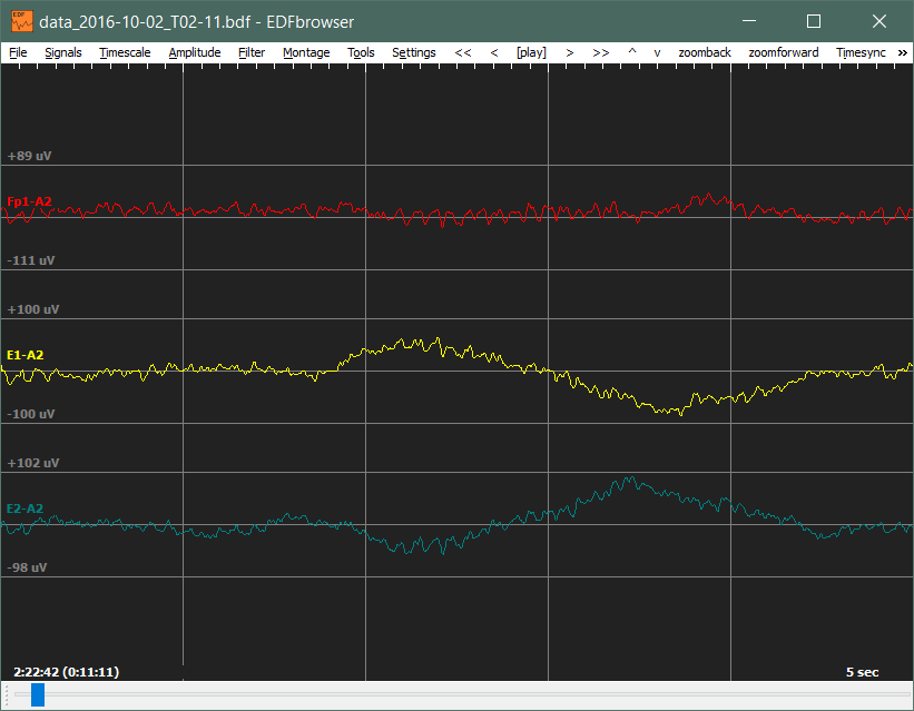
    Here, I replicate the above experiments using the OpenLD platform. The results of my eye-movements are shown below:

    Here, I moved my eyes left - right for around 2 to 3 times. You can see the out-of-phase deflections from the EOG signals that indicates eye movement.

    As of right now, it is too early to mark that as a successful attempt, but it is nonetheless a motivating result. I will continue to experiment with the OpenLD platform and post more results in the future. Thanks!

    Sources:

    Windt, Jennifer M., "Dreams and Dreaming", The Stanford Encyclopedia of Philosophy (Spring 2016 Edition), Edward N. Zalta (ed.),

  • The Software: OpenLD First Analysis

    Jae Choi10/01/2016 at 21:14 0 comments

    Results

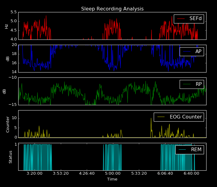
    A plot showing the analysis of sleep ranging from around 3:20 AM to 6:50 AM is shown below:

    The first 3 graphs show the statistical values for the REM stage detection algorithm (SEFd, AP, and RP). You can see that whenever the REM stage takes place, the SEFd value increases dramatically while the AP and RP values decrease. The results of the algorithm is shown in the last (fifth) plot.

    Again, we should remind ourselves that during REM stage, there are Rapid Eye Movements (duh). Therefore if our program is working correctly, then the results calculated from the EEG brainwave signals must be filled with eye movements.

    Let's see if that is true: the fourth graph shows the EOG counter, which is the frequency of eye movements detected from the EOG channels. We can see clearly that there is a correlation between eye movements (yellow) and the REM stage (blue)!

    Note that the REM stage shown in the graph was calculated only from the EEG electrode and not from any of the EOG channels. Therefore, the correlation between the two demonstrates that our program, is indeed, correctly detecting REM stages!


    Example of Sleep Stages

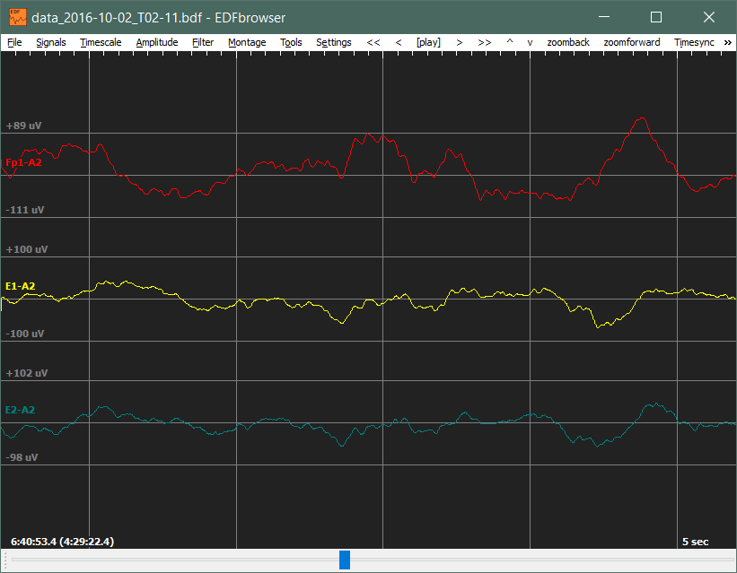
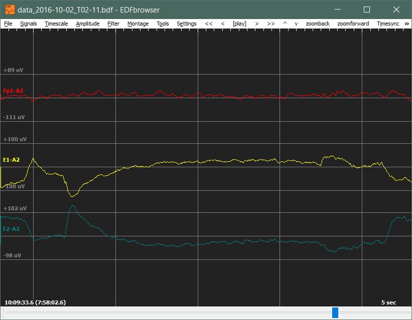
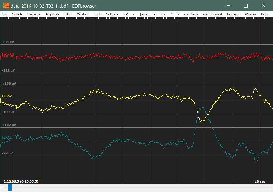
    According to the OpenLD analysis software, here is how each sleep stages look like. Note, the EEG signal has a red color while EOG Eye movement signals are yellow and dark blue.

    Awake Stage: Note the presence of Alpha waves (10 Hz) and slow, eye movements (out-of-phase signals)

    NREM: Note the presence of Delta waves ( > 4 Hz) and no eye movements (the two signals are in-phase)

    REM: Note the lack of presence of alpha/delta waves and the presence of Rapid Eye Movements.

    Reference used for the above evaluation

    Benbadis, S. R., & Lutsep, H. L. (2015, October 12). Normal Awake EEG. Retrieved October 02, 2016, from http://emedicine.medscape.com/article/1140143-overview


    Now we know that the OpenLD platform can successfully detect whether or not a person is dreaming. This is essential in inducing Lucid Dreams. In the next post, I will discuss how I will induce Lucid Dreams by making the OpenLD play a sound in my dreams. Stay tuned!

  • The Software: The Full OpenLD Analysis Program

    Jae Choi10/01/2016 at 20:38 1 comment

    In this post, I will now talk about the complete OpenLD analysis software. I will demonstrate what it does and how to use the software. All the source code for the software is located in the Github repo here! (Also located on the left Project sidebar). A pre-alpha windows build will be available very soon in the Github repository.

    OpenLD Software Overview

    Here is a GIF File demonstrating the program in use:

    We enter information such as the number of channels that we are going to use, the channel labels, the EEG channel number, and the delay for alarm (in hours). Afterwards, it connects to the OpenLD and initiates a terminal over the Bluetooth SPP. In this terminal prompt, appropriate channels can be activated (C#) along with impedance checking (I#). Commands such as P and S displays the ADS1299 internal registers, while the command E exits the terminal and starts the analysis procedure.

    The next display shows the impedance values, which shows signal connection quality, and the current status and time. The program continuously displays the above information until the user manually quits the program using Control-C.

    This is where all the REM analysis takes place. A sound file, that is in the same directory as the executable, with a name rem_alert.wav is played when an appropriate REM stage is detected. Then, it will wait at minimum 7 minutes before another trigger to give the dreamer a chance to induce Lucid Dreams.

    When the program is running, it logs the received bio-signals into a BDF file called data_###.bdf, where ### contains the date and time information. Also, it logs the analysis information, which contains values for SEFd, AP, RP, Eye Movement counter, and REM stage status, into a file called analysis_###.txt, where ### is again the date/time.

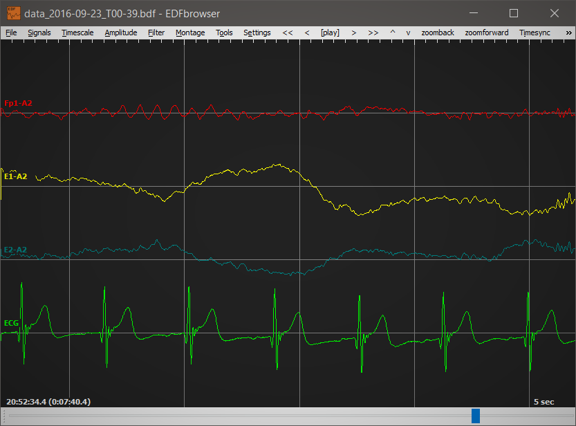
    The BDF file (data_###.bdf) can be opened with an open-source browser called EDFBrowser by Teuniz:

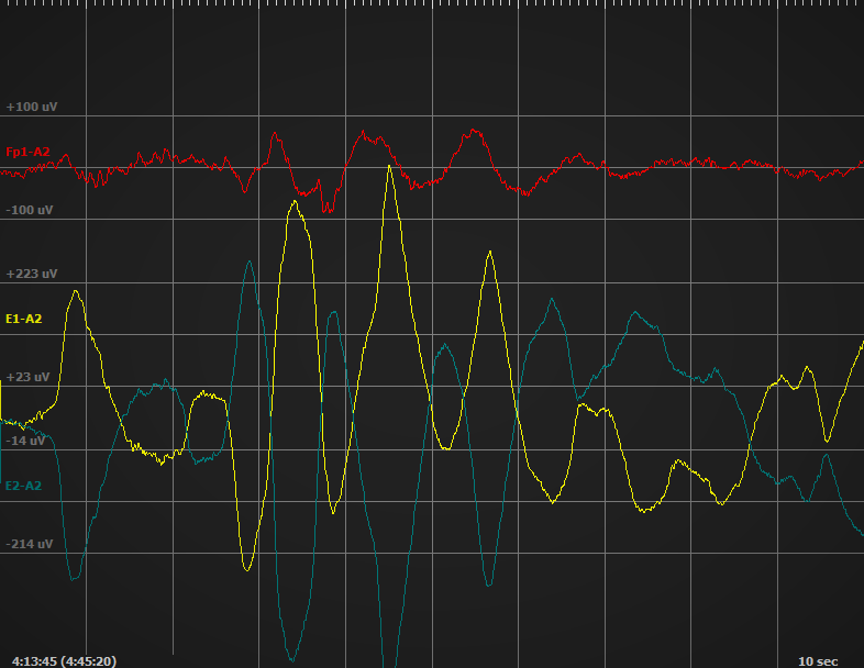
    The above shows the Fp1-A2 forehead EEG channel along with two EOG channel electrodes. You can see the prominent alpha rhythm (10hz), which is induced when a subject has his/her eyes closed and relaxed. (Benbadis et al.)

    More information about the program will be presented as it is developed. Currently, the program is in a pre-alpha state, hence there are many improvements that will be made. However, it is fully functional to induce lucid dreams! In the next project post, I will demonstrate what different type of sleep stages look like and evaluate the performance of the software.


    Sources

    Benbadis, S. R., & Lutsep, H. L. (2015, October 12). Normal Awake EEG. Retrieved October 02, 2016, from http://emedicine.medscape.com/article/1140143-overview

  • The Software: EOG REM Detection Implementation (Code)

    Jae Choi09/28/2016 at 20:00 0 comments

    Now that we have derived the expression (the Inverse Dot Product) for calculating the magnitude of eye movements, we can begin its implementation. The C++ code for it is pretty simple:

    int remDetect::evaluate_EOG_REM_Epoch(double *EOG1, double *EOG2, double min_EOG)
    {
        // Resat accumulator
        avg_EOG_IP = 0;
        // Optimized algorithm - it is equivalent with += (EOG1 - EOG2)^2 - (EOG1 + EOG2)^2
        for (int i = 0; i < m_size_window; i++) {
            avg_EOG_IP += -1.0 * EOG1[i] * EOG2[i];
        }
        // Average
        avg_EOG_IP /= m_size_window;
        // if the value is within the limit window then return 1, else 0
        if (avg_EOG_IP > min_EOG) {
            rem_eog_Counter++;
            return 1;
        } else return 0;
    }
    

    In the code, you can see that I average (divide by number of EOG data points) the IDP after it has been calculated. This is to make sure that the constant min_EOG does not depend on the length of the signals and hence is portable across different EEG sampling frequencies. This function will return a 1 if it detects enough eye movements (above the min_EOG threshold) and a 0 otherwise.

    There it is. We are done with the Lucid Dream Trigger portion of this project. In the next Project Log, I will give a general overview of how to use the OpenLD Software.

  • The Software: EOG Eye Movement Detection Overview

    Jae Choi09/28/2016 at 10:09 0 comments

    Last time, I talked about the EEG REM detection portion, which was the first REM verification step of the program. However, to further increase the accuracy of the detection algorithm, another REM detection algorithm is used. This algorithm will use EOG (Electrooculography) to detect Rapid Eye Movements (REM) during REM sleep.

    Derivation of the EOG Eye Movement Detection Algorithm

    If you are not interested in the mathematics of the algorithm, skip to the next section!

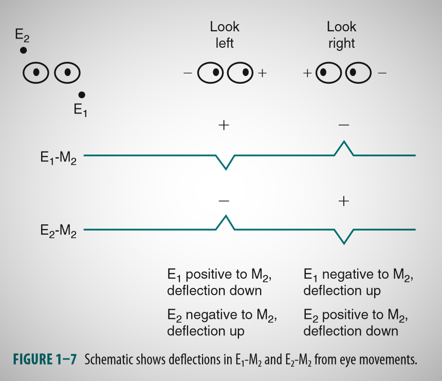
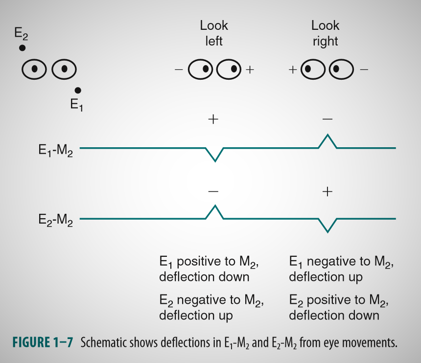
    Eye movements produce a specific pattern in EOG signals, due to the potential difference between the front and the back of a human eye. This pattern is described in the figure below: (Adapted from Kerkhof, G. A., & Van Dongen, H.)

    As you can see from the above figure, eye movements produce deflections which are always out of phase between the two EOG channels.
    The EOG REM detection algorithm relies on this fact to detect eye movements. Since the signals are out of phase, when we add the two signals, they cancel each other out. In contrast, if we subtract the two channels, the patterns add up. By combining these two features and taking their square, we can create the following formula:

    where N is the length of the current signal (which is 250 SPS * 2s = 500 for 2 seconds of data), EOG1 is the E1-A2 channel and EOG2 is the E2-A2 channel. The EM value will be high for out-of-phase signals (thus eye movements), and low for signals which are in-phase (such as noise, muscle artifacts, etc.).

    If we simplify the formula, we obtain the following: (Note, I replaced EOG with E for simplicity)

    We can see that the formula simplifies to a negative dot product if we ignore the constant 4. This is quite intuitive: Taking a dot product of two signals yield a value that indicates how "similar" the two signals are ("signal correlation"). But if we inverse the value, then the value reflects how "different" the two signals are. This is desired as the eye movements are always out of phase.

    This feature is called the Inverse Dot Product (IDP).

    Implementation of the Algorithm

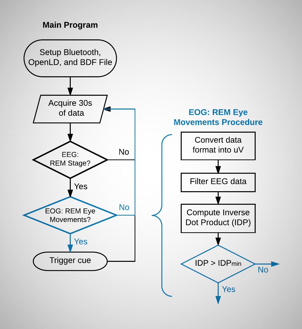
    The implementation closely follows to that of the EEG REM detection algorithm, described in the previous Project Log. Here is the corresponding flowchart:

    Like before with the EEG data, the EOG data is converted to micro-volt format and filtered with a band-pass filter (0.1hz - 35hz). The Inverse dot product for 2 seconds of the data (which is 500 samples for 250 samples per second A/D speed) is then computed and compared to a minimum threshold (IDP min). If the current sleep stage is determined to be REM, and the IDP is larger than the minimum constant, the sleep stage is determined to be REM and a lucid dreaming trigger is cued.

    In the next Project Log, I will talk about the code for the above implementation.

    Sources:

    Kerkhof, G. A., & Van Dongen, H. (2010). Human Sleep and Cognition: Basic Research (Vol. 185). Elsevier.

  • The Software: EEG REM Detection Implementation (Code)

    Jae Choi09/25/2016 at 14:21 0 comments

    In the previous Project Log, I talked about the EEG REM Detection algorithm (Imtiaz et al.). In this log, I will talk about the implementation of the algorithm in C++. Note, for the OpenLD software, I will be using Qt C++, due to its extensive cross-platform support and ease of use.

    Implementation of REM Detection

    I will list the C++ code along with its corresponding formula, which are explained in depth in the previous Project Log.

    SEFd (Spectral Edge Frequency difference)

    SEF(x) where x in the Percentage of Edge Frequency:

    #define FREQ_TO_BIN(x, N_FFT, Fs) int(x * N_FFT/Fs)
    #define BIN_TO_FREQ(x, N_FFT, Fs) int(x * Fs/N_FFT)
    
    double remDetect::SEFx(double *spectrum, int x, int f_Start, double sum_SEF)
    {
        double sum_fft = 0;
        for (int i = FREQ_TO_BIN(f_Start, m_size_fft, m_Fs); sum_fft < ((double)x) / 100.0 * sum_SEF; i++) {
            sum_fft += spectrum[i] * spectrum[i] * ((double)m_Fs) / ((double)m_size_fft);
        }
        return (((double)i) * ((double)m_Fs) / ((double)m_size_fft));
    }


    SEFd: the difference between SEF95 and SEF50

    SEFd[epoch_Counter] = SEFx(spectrum, 95, f_Start, m_SEF_sum) - SEFx(spectrum, 50, f_Start, m_SEF_sum);
    

    AP (Absolute Power) and RP (Relative Power)

    Absolute Power

    double remDetect::absPower(double *spectrum, int f_Start, int f_End)
    {
        double sum_fft = 0;
        for (int i = FREQ_TO_BIN(f_Start, m_size_fft, m_Fs); i <= FREQ_TO_BIN(f_End, m_size_fft, m_Fs); i++) {
            sum_fft += spectrum[i] * ((double)m_Fs) / ((double)m_size_fft);
        }
        return ((double) 20.0 * log10(sum_fft));
    }
    

    Relative Power

    double remDetect::relPower(double *spectrum, int f_Start, int f_End)
    {
        double ratio_spectrum = 0;
        ratio_spectrum = absPower(spectrum, f_Start, f_End) - absPower(spectrum, 1, f_Max);
        return ratio_spectrum;
    }
    

    Decision Tree for REM Detection

    int remDetect::evaluate_REM_Epoch()
    {
        // If the SEFd value is bigger than the specified minimum
        if (avg_SEFd > m_min_SEFd) {
            // If the averaged Absolute power is smaller than specified maximum
            if (avg_AP < m_max_AP) {
                // If the averaged Relative power is between the specified interval
                if (avg_RP > m_min_RP && avg_RP < m_max_RP) {
                    // REM DETECTED :D
                    return 1;
                } else return 0;
            } else return 0;
        } else return 0;
    }
    

    Sources

    Imtiaz, Syed Anas, and Esther Rodriguez-Villegas. "A low computational cost algorithm for rem sleep detection using single channel EEG." Annals of biomedical engineering 42.11 (2014): 2344-2359.

  • The Software: EEG REM Detection Overview

    Jae Choi09/24/2016 at 18:18 0 comments

    In order to induce Lucid dreams, the program has to detect that the subject is dreaming (refer to the previous build log for more information). As dreaming occurs in Rapid Eye Movement (REM) sleep stage, the OpenLD detects this through EEG and EOG signals. Today, I will be talking about the EEG REM detection portion of the project.

    The EEG REM Detection Algorithm Overview

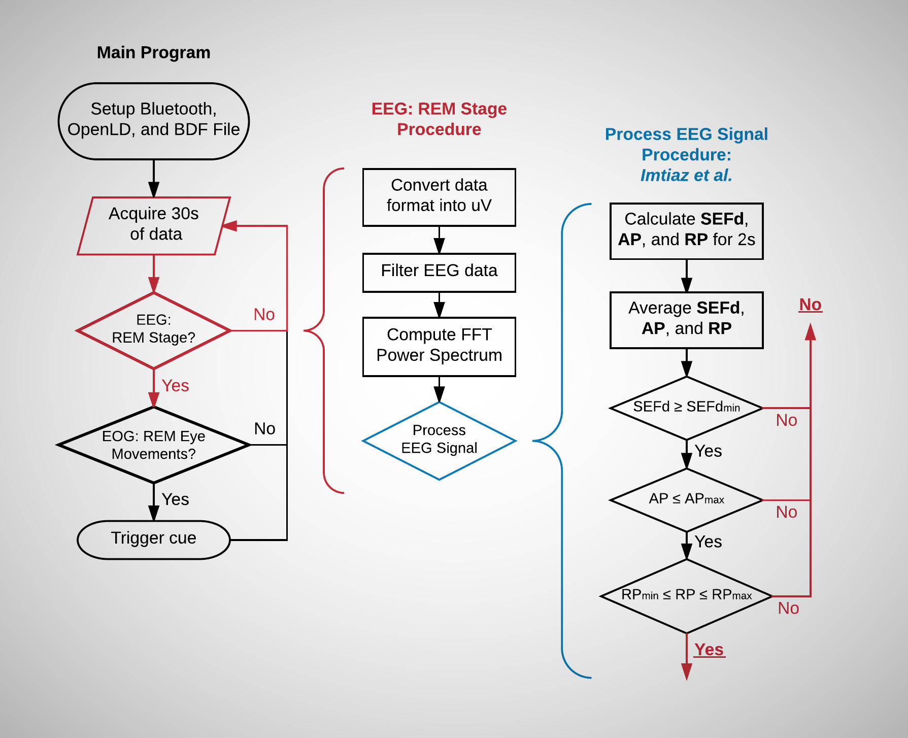
    The OpenLD software uses an algorithm developed by Imtiaz et al. to detect REM state from the EEG signal. Detailed flowchart for this algorithm is shown below:

    The Main Program section of the flowchart is identical to that of the previous Project Log. As I've explained before, the program has 2 verification steps (EEG: REM Stage and EOG: REM Eye Movements). This log will talk about the first EEG step of the verification process.

    I've divided the flowcharts in an exploded, side-by-side view so that it wouldn't get too long and unreadable. The flowchart of the EEG: REM Stage is shown in the middle of the above diagram, while the flowchart for the Process EEG Signal step is shown on the far right.

    Here is how the program works: After the initialization process, the program acquires 30 seconds of data from the OpenLD. Then, it converts the 24 bit raw data to the required micro-volts (uV) scale. Afterwards, it filters the scaled data with a bandpass filter with a pass-band of 0.3hz to 35hz. This filter helps to remove the voltage offset from the electrodes and mains 50hz/60hz noise.

    Finally, the data is Fast Fourier Transformed and its power spectrum is calculated. Using the spectral information, the values SEFd (Spectral Edge Frequency), AP (Absolute Power), and RP (Relative Power) are determined. This statistical information is used to determine the REM sleep state of the EEG. More information about these values are explained below.

    Mathematics of the REM Detection Algorithm

    Note: If you do not like to delve into the mathematical details, you can ignore this discussion and skip to the next section: Decision Tree for REM Detection

    The algorithm proposed by Imtiaz et al. relies on these three values: SEFd, RP, and AP. Although I give the general gist here, please refer to the paper for more information.

    SEFd (Spectral Edge Frequency difference)

    SEF basically is the "frequency below which a certain fraction of the signal power is contained". For example, "SEF at 50% (SEF50) is the lowest frequency below which half of the signal power is present" (Imtiaz et al.).

    Here is the formula that calculates the value of SEF50. Here, the SEF50 value (x) is the frequency below of which it contains 50% of the power spectrum (Xi2) that ranges from f start to f end. (Imtiaz et al.).

    and here is one for SEF95:

    Here is the formula that calculates the value of SEFd. It is simply the difference between SEF95 and SEF50.

    AP (Absolute Power) and RP (Relative Power)

    Absolute Power is the logarithmic power spectrum from frequency fstart to fend. Its formula is given below:

    Relative Power is "the ratio of the absolute powers of the signal in the range of interest and the entire signal bandwidth." (Imtiaz. et al). Since we are band-pass filtering our signal at 0.3hz to 35hz, that is our frequency bandwidth. The formula is shown below:

    This is equivalent to the formula below. Remember your rule of logarithm division rule!:


    Decision Tree for REM Detection

    After the above calculations, the SEFd, AP, and RP values are compared against a set of constants to determine if the current signal is a REM state. If we go back to the flowchart above, we can see that there is a decision tree involving these constants.

    In order for it to be an REM state:

    • its SEFd value has to be bigger than SEF min constant
    • its AP has to be smaller than AP max constant
    • its RP value should be in between RP min and RP max constants.

    If that is the case, then the subject is currently in REM state.


    Now that was a rather tedious Project Log... I promise that things will now get much more exciting. In the next post, I will...

    Read more »

  • First Recording of EEG, EOG, and ECG Signals!

    Jae Choi09/24/2016 at 14:25 0 comments

    Now since both the OpenLD hardware and software are now more or less completed, here is a 5 second recording of EEG (Fp1-A2), EOG (E1-A2 and E2-A2), and ECG signals, viewed from an open-source software called EDFBrowser.

    The signals were recorded when I was awake, with eyes closed. You can see the EEG Fp1-A2 electrode (red), EOG E1-A2 (left eye - yellow) / E2-A2 (right eye - blue) signals, and the ECG (Electrocardiogram - green) signal above.

    Note: The reason we need two channels for EOG is due to the fact that the eye movements produce a complementary/out-of-phase signal. For instance, we can see that when the left eye E1-A2 (yellow) trace reflects upwards, the right eye E2-A2 (blue) trace reflects downwards. Other activity that is in-sync/in-phase is NOT eye movement activity.

    In the next few Project Logs, I will talk about the implementation and the mathematics of the OpenLD Analysis porgram. Afterwards, I will hopefully post a full sleep recording and evaluate the REM detection performance of the software.

  • The Hardware: OpenLD Electrodes

    Jae Choi09/24/2016 at 13:57 3 comments

    OpenLD Passive and Active Electrodes

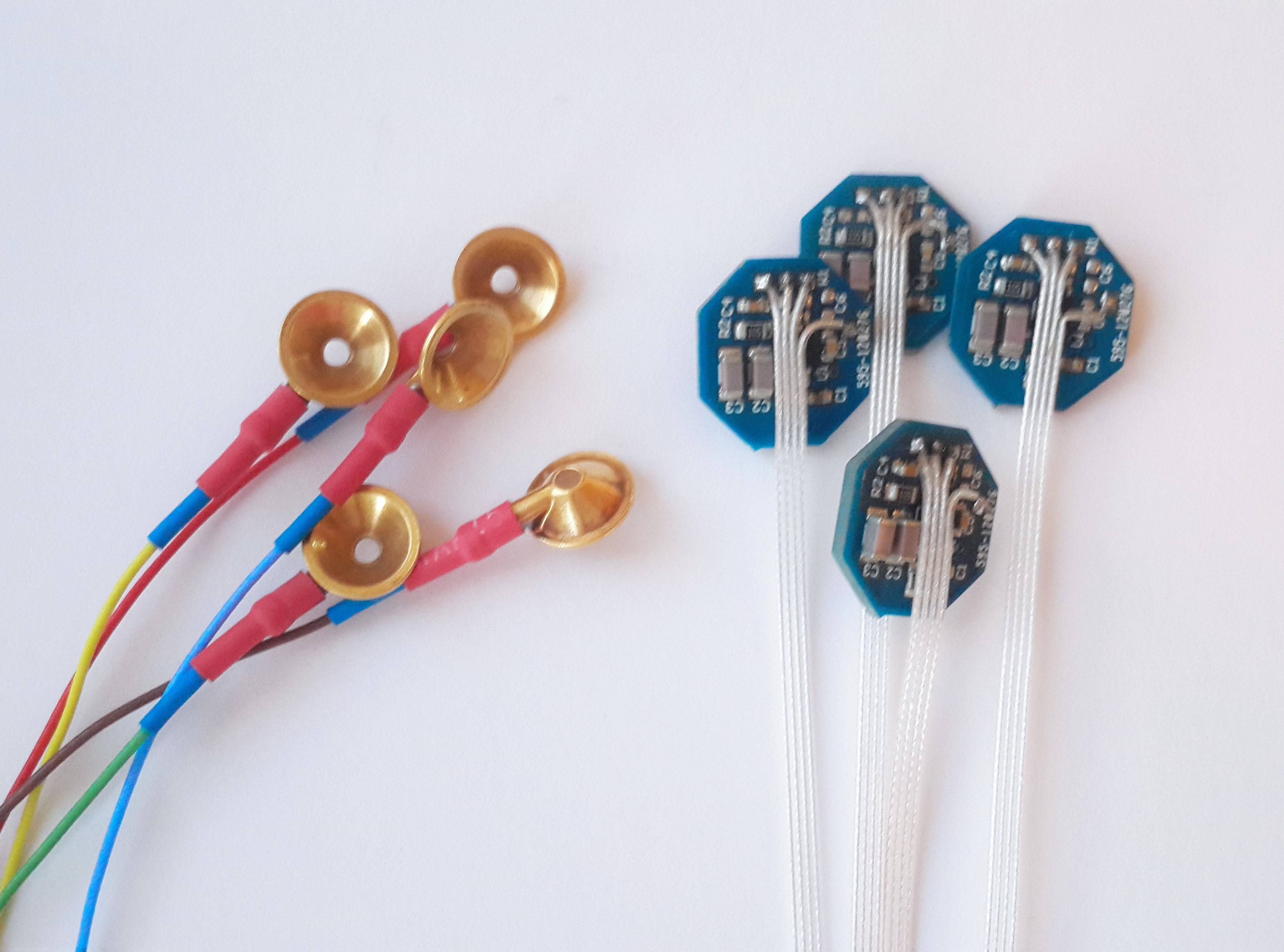
    I've realized that I forgot to mention the type of electrodes I am using for the OpenLD hardware. Below is a picture of passive gold cup electrodes on the left and active electrodes on the right:

    The main differences between these two type of electrodes is that the passive electrodes require skin preparation while the active electrodes do not.

    The gold cup electrodes above need to be filled with a conductive electrode gel (I use a Ten20 paste) in order to reduce the electrode impedance. However, the active electrodes contain an on-board high-impedance amplifier (in a voltage follower configuration) and corresponding circuitry that takes care of the high impedance nature of the EEG signals.

    As of right now, the active electrodes are working and provide excellent quality EEG/EOG signals. I will talk about the board layout and the schematics in a future Project Log. Although I am currently using passive electrodes, I will eventually transition to using the active electrodes in the near future. Stay tuned!

    Electrode Placement for the OpenLD

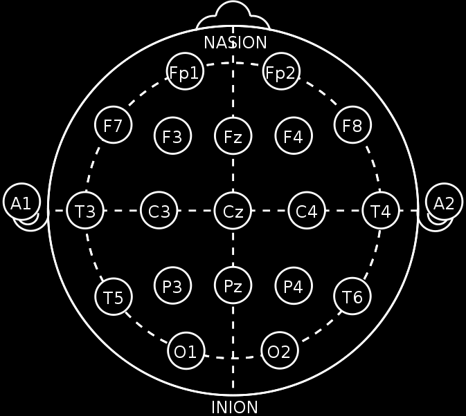
    Here is a simple 10-20 diagram that shows the EEG electrode location sites. This figure was adapted from Wikipedia:

    In order to detect REM sleep, the signals from the prefrontal cortex of the brain has to be measured. (Imtiaz et al.) Therefore, the positive (non-inverting) EEG electrode is placed on the location Fp1 above, which is on the left side of the forehead. Since differential amplifiers are being used, the negative (inverting) electrode is placed on the site A2, which is behind the right ear, as a reference. This EEG electrode setup is labeled as Fp1-A2.

    Furthermore, EOG electrodes need to be placed in order to detect eye movements. Therefore, an E1 non-inverting electrode is placed 1 cm directly below the leftmost corner of the left eye. Also, an E2 electrode is placed 1 cm above the rightmost corner of the right eye. These electrodes, like the EEG Fp1 electrode, are referenced to A2 as well. They are labeled as E1-A2 and E2-A2.

    The above diagram shows the placement of E1 / E2 electrodes and how eye movements translate into electrical signals in the EOG trace. This will be important later when we are examining the REM EOG signals. (Diagram adapted from Kerkhof, G. A., & Van Dongen, H. Human Sleep and Cognition: Basic Research)

    We can now perform a sample recording. I will post an EEG/EOG/ECG recording in the next Project Log.

    Sources:

    Imtiaz, S. A., & Rodriguez-Villegas, E. (2014). A low computational cost algorithm for rem sleep detection using single channel EEG. Annals of biomedical engineering, 42(11), 2344-2359.

    Kerkhof, G. A., & Van Dongen, H. (2010). Human Sleep and Cognition: Basic Research (Vol. 185). Elsevier.

View all 15 project logs

  • 1
    Step 1

    To Build or Not to Build: The OpenLD Hardware

    I have to emphasize that the design files I have provided above are prototypes. There are safety features that are not yet implemented which can be quite dangerous if misused. Therefore, I recommend that you either improve upon the above design or get an OpenBCI board as an alternative. Although the OpenBCI platform is not yet supported, it definitely will be in the future.

  • 2
    Step 2

    Building the OpenLD Hardware

    There is not much to say here. I only recommend building your own OpenLD board if you have some experience with surface mount soldering. The OpenLD Fabrication Documentation will come very handy during the build, especially page 5 which shows the individual component placements on the PCB.

    When you finish soldering the components, it is important to bridge (short out by placing a blob of solder) the S4 jumper that is located on the bottom side of the PCB. This jumper connects the chip select pin of the ADS1299 to the STM32F4 microcontroller.

    I advise you to buy male 1.27mm male headers (not 2.54mm headers!) in order to connect wires to the headers present on the OpenLD board. These small headers are an absolute pain to work with, but their small form factor is definitely advantageous over the traditional 2.54mm headers.


  • 3
    Step 3

    Programming the STM32F4

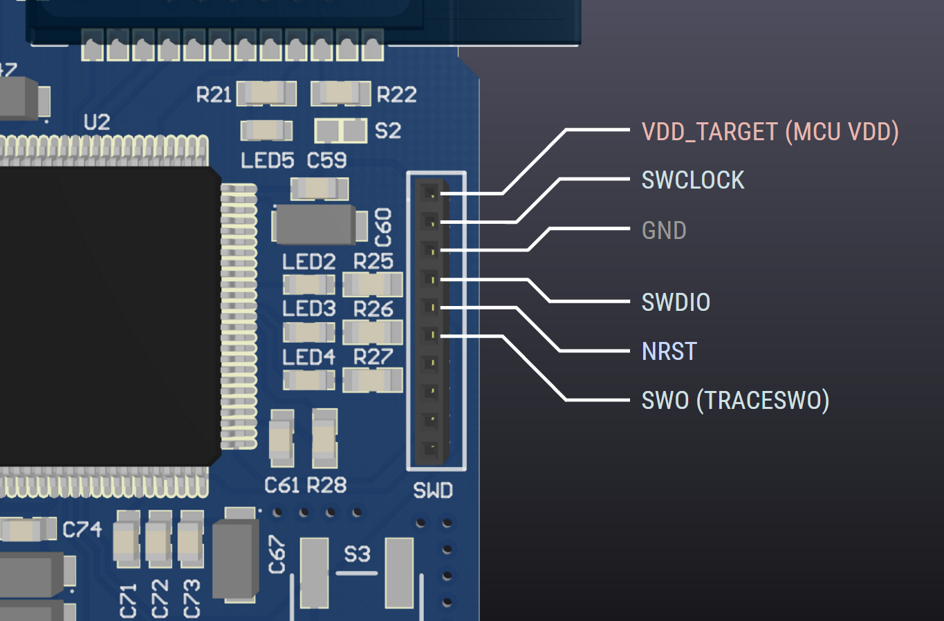
    You can either use the STM32Discovery/Nucleo boards or a dedicated STLink V2 programmer to burn the firmware to the OpenLD board. Just make the necessary connections between the SWD connector on the OpenLD board to the programmer. Refer to the schematics in the OpenLD Fabrication Documentation and the below diagrams to figure out which connections go where:

    OpenLD SWD Pinout

    STM32Discovery SWD Pinout (User Manual - Page 15). Make sure to remove CN3 Jumpers! Also, ST-Link V2 SWD Pinout (User Manual - Page 12)

View all 7 instructions

Enjoy this project?

Share

Discussions

Juan Manuel Roa Mejia wrote 02/23/2024 at 16:23 point

Hi, i just found your project and wow! It merges different disciplines i would like to skill. Do you guys are still working on it? I'm highly interested in contribute.

  Are you sure? yes | no

William J Croft wrote 10/09/2022 at 00:16 point

Jae, thanks for the 2022 update and future plans. Hope you consider offering this on CrowdSupply or similar platform.

  Are you sure? yes | no

addy.cdc wrote 12/07/2020 at 12:43 point

Thank you for starting this project and providing the full and detailed documentation! It is a very interesting project with lots of potential! I've decided to start the hardware manufacturing and perform some tests to see how well it works. I hope this project will still be active and grow while more people will pitch-in.

Since the STM32F4 has DSP capabilities, I wonder if it would be possible to port the FFT processing on the DSP itself, rather than on a remote PC / Smartphone. It will need some HW modifications in order to trigger cues (add RGB LEDs, vibration motors, sound, etc), It will definitely reduce RF radiation exposure close to the brain, since the session can be saved on the uSD card and sync-ed in the morning with the GUI application for analyzing/logging the results.

Some improvements I see worth doing on the next HW re-spin:

- reduce the PCB footprint (e.g. less channels, place components on both sides, etc)

- add a Li-po battery, charger and fuel gauge

- use flexible PCB and housed in a flexible 3D printed enclosure (TPU or TPE). This will help with comfort during long wearing sessions

- embed active electrodes in the enclosure / band, so that everything is fully contained and no wires hanging

- optionally adding more sensors like accelerometer as well as temperature probe touching the skin

  Are you sure? yes | no

Alberto Sanchez wrote 03/04/2019 at 17:00 point

Hi, I was reading your blog lately, and I have a really specific question. You mention this about your interrupt for sending the data to the bluetooth: "Meanwhile, interrupt EXTI0_IRQHandler is triggered when 250 samples are received in the buffer, hence every second", if you are having 250 SPS that means a 4ms period, how is that you send the data every second? 

Thanks.

  Are you sure? yes | no

Daniel Cervantes wrote 12/10/2017 at 10:07 point

I'm curious, roughly how much do all the parts cost in total? I doubt I could ever make something this technical given my very limited experience with hardware, but it's intriguing nonetheless.

  Are you sure? yes | no

r.akhavan wrote 07/04/2017 at 09:49 point

Hi again jae
unfortunately our stm32 code doesnt compile.

i see this error on log file "Failed to parse IAR project format file" 

  Are you sure? yes | no

raoul wrote 07/10/2017 at 11:26 point

  Are you sure? yes | no

r.akhavan wrote 07/10/2017 at 11:51 point

i see your link .. but i want to change the codes and couldn't open it with any compiler  .. atollic compiler show me this error "Failed to parse IAR project format file"

how change the code ?? 

  Are you sure? yes | no

r.akhavan wrote 06/13/2017 at 08:55 point

Hi jae! which compiler you use for STM ?

  Are you sure? yes | no

r.akhavan wrote 06/28/2017 at 09:12 point

i find it .. "Atollic "
tanx

  Are you sure? yes | no

raoul wrote 12/10/2016 at 18:08 point

Can you give some hints wich electrode ports to connect to?

  Are you sure? yes | no

raoul wrote 11/19/2016 at 15:38 point

Managed to flash firmware  with ST link V2

the ADS1299 Led seems not to be blinking - I had to buy replacement for OSC1 since they not had the recommended one in stock replaced with http://www.mouser.com/ds/2/268/DSC1001_Datasheet-775857.pdf

In the schematic pdf,  PIN1 from osc1 supposed to be "pin4"  on the picture in this project your PIN 1 from osc4 seems on pin 4 from schematic, is this correct?

  Are you sure? yes | no

Jae Choi wrote 11/19/2016 at 16:31 point

The ADS1299 LED is not blinking because it is not supposed to blink :). I haven't coded anything to turn LED1 on. The LED that blinks every 1 second (LED2) tells me that the ADS1299 is working and acquiring data at 250 samples per second.

However, you shouldn't be able to see anything if you connect to the board via Bluetooth. You need to change the RN42 default baudrate (115200) to the OpenLD's baudrate (230400). Check the instructions on how to do this

Note: Can you check if the supply rail for the STM32F407 is 3.3V? There was an error in the documentation that showed the wrong part for the voltage regulator (It should be TPS73233 NOT TPS73225. I fixed this error now). Also, make sure the S4 jumper is shorted, as stated in the instructions above!

Thanks! Please reply if you have any other issues!

  Are you sure? yes | no

raoul wrote 11/21/2016 at 02:40 point

changed baudrate en BT name, all seems ok. Need executables now
supply is 2.5 volt.  So only need to change U5? or U3 also? 

  Are you sure? yes | no

raoul wrote 11/24/2016 at 16:26 point

Changed to tps73233 now

  Are you sure? yes | no

raoul wrote 11/13/2016 at 16:05 point

Orderd some pcb's and components and build one. Now stuck at programming the MCU. Any hints on that?

  Are you sure? yes | no

Jae Choi wrote 11/18/2016 at 08:16 point

Hi! In the past couple of days I've been writing documentation for this project. I'll be uploading full instructions on how to build the hardware, compile & burn the firmware to the MCU, and use the OpenLD software today. I'm sorry for the delay :(. Thanks!

  Are you sure? yes | no

[deleted]

[this comment has been deleted]

Jae Choi wrote 10/20/2016 at 08:34 point

Sorry for the late reply! That is strange, as my manufacturer (Hackvana) did not complain about any issues with the outlines. I'll try to look into this issue and will get back to you as soon as possible.

  Are you sure? yes | no

Andras F wrote 10/10/2016 at 06:46 point

Hi Jae! Great project, congrats! I would be interested to join you in the development. I started the Hungarian Lucid Dreamer's Club (https://www.meetup.com/Tudatos-Alom-Klub-Budapest/) 3 years ago so I am in costant contact with lucid dreamers, and I also into C++ and improved the EDFBrowser myself (https://github.com/andrasfuchs/EDFbrowser/wiki) when I did my own experiments. Drop me a line if you are interested in any kind of cooperation, I would be glad! Cheers, Andras

  Are you sure? yes | no

Jae Choi wrote 10/20/2016 at 08:33 point

Thanks! Sorry for the late reply. Right now, I am mostly spending my time documenting my project and improving various parts of my projects here and there. Just to let you know, right now, I am currently planning to support OpenBCI series of hardware for my program. I will keep this project updated as I go. Again, thanks for your help!

  Are you sure? yes | no

David J. Sandoval wrote 09/26/2016 at 09:56 point

I guess you know the work of Dr. Ursula Voss (A neurobiological model of lucid dreaming and others).
She uses brain stimulation AC 40 Hz (TACS). They are very interesting.
Incorporate electrical stimulation on your computer could be very interesting.
Regards
David Sandoval

  Are you sure? yes | no

Jae Choi wrote 09/26/2016 at 13:54 point

Yes I actually follow her studies very closely. They are very interesting; I've cited her study in the "Details" section above as an example of how lucid dreams can be used for scientific research. 

Concerning the famous tACS 40hz study, I have actually designed a tACS device, but the project is currently in limbo. I am very interested in revisiting this idea, so I'll give a heads up if I manage to do so.

Thanks!

  Are you sure? yes | no

David J. Sandoval wrote 09/26/2016 at 18:48 point

Soon I will start with my team Tacs. Is still very poor. When I start I will publish here. It will be a pleasure to know your opinion.

I think the most important thing of all is the ease of use of the equipment, because it is for use in sleep. So the electrodes should be comfortable to wear. Greetings.

  Are you sure? yes | no

Ken wrote 03/29/2017 at 18:07 point

Voss's study is rather deeply flawed when it comes to really inducing lucid dreams.  She came up with her own scale of different attributes of dreaming, and what she decided to define as a "lucid dream" was missing the key attribute of the dreamer fully realizing that he's dreaming (this attribute did *increase* with TACS, but still well below the range of the attribute for non-lucid dreams)!   There are in-depth discussions of this study on lucid dreaming sites like DreamViews.      TACS has not yet proven itself to be even a somewhat useful EILD (electronic inductin of lucid dreams) approach.

  Are you sure? yes | no

orscosp wrote 09/11/2016 at 00:45 point

Thank you for your interest. Electrodes not-contact build on LMP7702MM, I encountered trouble when multiplexing can not, namely, the output of the electrode is 4 lines, including (VDD, Vref, Vout, Vss) my project need 4 channels to record brain waves, the region applied to the prefrontal region, namely the coordinates of the electrodes (Af7 / FP1 / FPZ / FP2 / AF8). I use location FPZ reference electrode, but I can not communicate is the output of the electrode with the input of the ADS1299. you can help make that happen I do not! thank you. My email (orscosp@gmail.com)

  Are you sure? yes | no

Jae Choi wrote 09/21/2016 at 17:39 point

Is it possible if you can provide a picture of your schematics through a Hackaday private message? I'm afraid I won't be much of help if I do not know the hardware configuration of your ADS1299. Sorry for the late reply by the way :(.

Thanks!

  Are you sure? yes | no

orscosp wrote 09/10/2016 at 10:37 point

jae Choi. Contact with me. orscosp@gmail.com

  Are you sure? yes | no

orscosp wrote 09/10/2016 at 10:36 point

Hello, I am working with the ADS1299, and I'm interested in the non-contact electrodes, but I did not get the channel coupling, you can help me do it not?

  Are you sure? yes | no

Jae Choi wrote 09/10/2016 at 16:41 point

I have actually experimented with non-contact active electrodes and built some working prototypes. The electrodes I have built are based on the LMP7702 op amps, which was inspired by a study I read somewhere.... 

Although the electrodes that I have built works very well, I had problems securing them onto the scalp (Tried using headbands but didn't work out). This is why I am currently using passive electrodes, but maybe in the future I will go back to them.

I will definitely upload build logs, with schematics and board files, regarding active electrodes soon. Meanwhile, I can try to help you out. Can you specify what you mean by "channel coupling"?

Thanks!

  Are you sure? yes | no

Jasper parker wrote 08/25/2016 at 14:41 point

How does this work? 

  Are you sure? yes | no

Jae Choi wrote 08/26/2016 at 18:07 point

I have updated the information in the project details above. Go check them out!

Thanks.

  Are you sure? yes | no

Similar Projects

Does this project spark your interest?

Become a member to follow this project and never miss any updates