-
The Hand in All it's Glory.
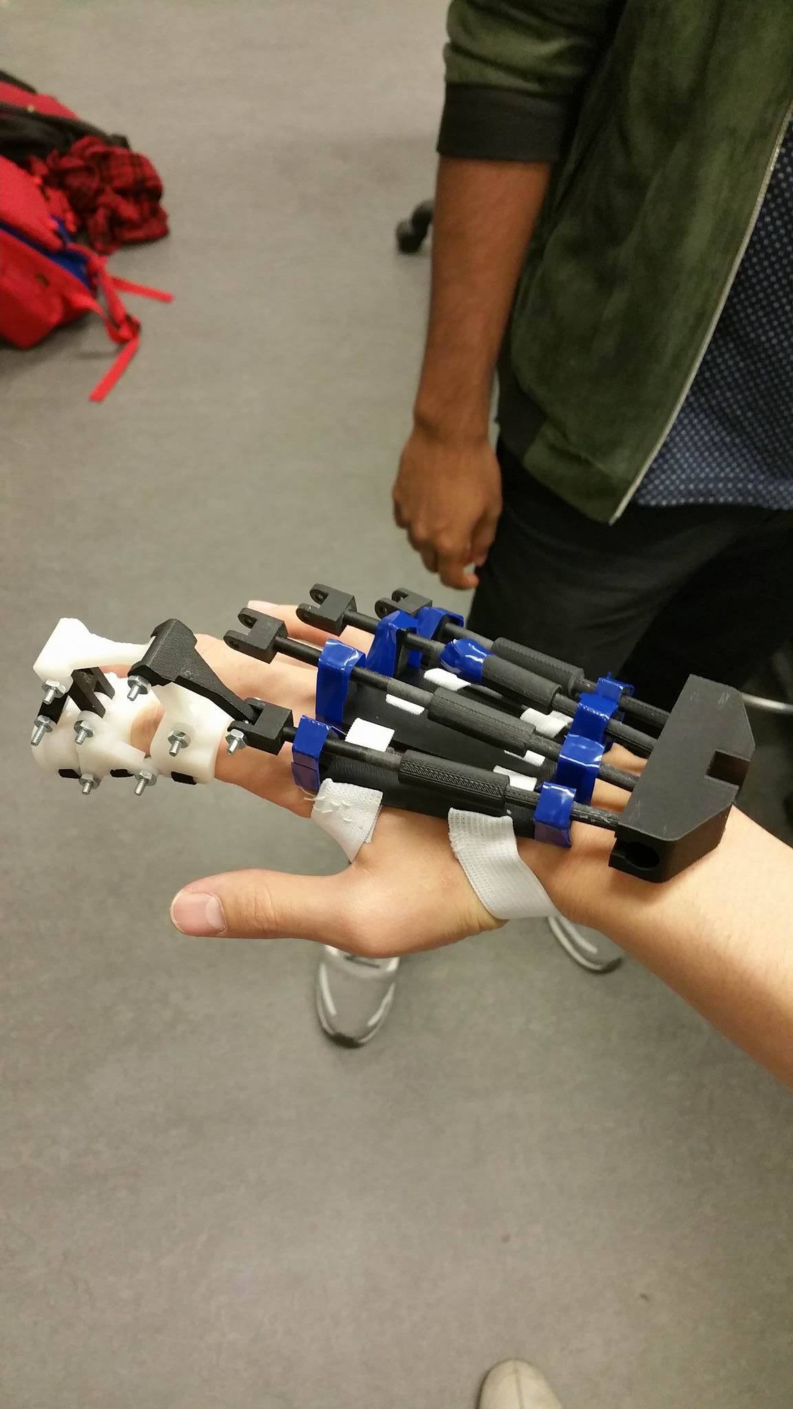
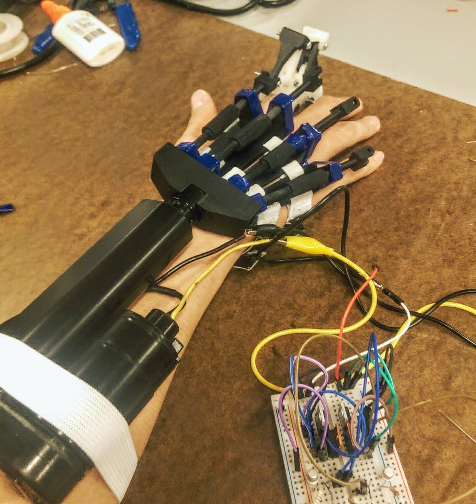
10/02/2016 at 15:26 • 0 commentsOver the past few days, the Beowulf team has been sprinting to get our first functional prototype assembled and working for the Hackaday Prize deadline.
We did it fam.
Not only did we get the entire hand assembled, but by combining the linear actuator with its h-bridge circuit and a Myo that's interfaced with an Arduino, we successfully achieved motion of the exoskeleton using EMG data from the Myo armband. Talk about clutch.
This is a video highlighting all of our hard work in this project (Using buttons to fine control the prototype for safety):
Beowulf is no where near complete, we learned so much from just this first successful prototype itself and we are going to continue to iterate and make our exoskeleton better and better. We learn as we go and even though we learned a lot, we still have a lot to learn.
Thanks for reading!
- Beowulf Team
-
Hand Assembly Part 1
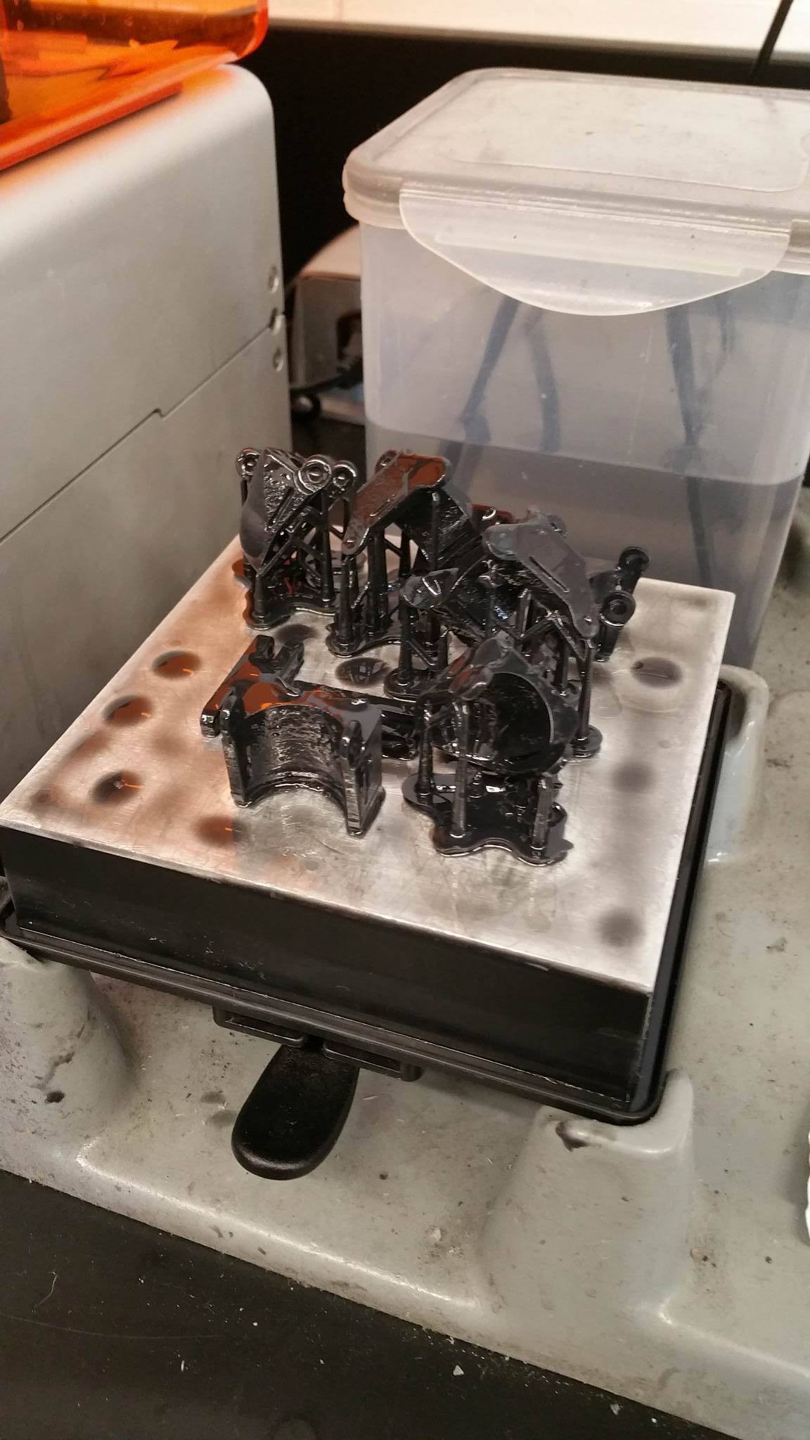
09/30/2016 at 02:05 • 0 commentsThe new parts were printed after applying appropriate tolerances. This time, the parts were printed using FormLabs Printer, which uses Resin instead of PC ABS.
![]()
The finished print.
Our team poured out about 3 hrs for the assembly.
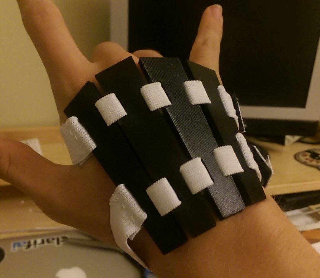
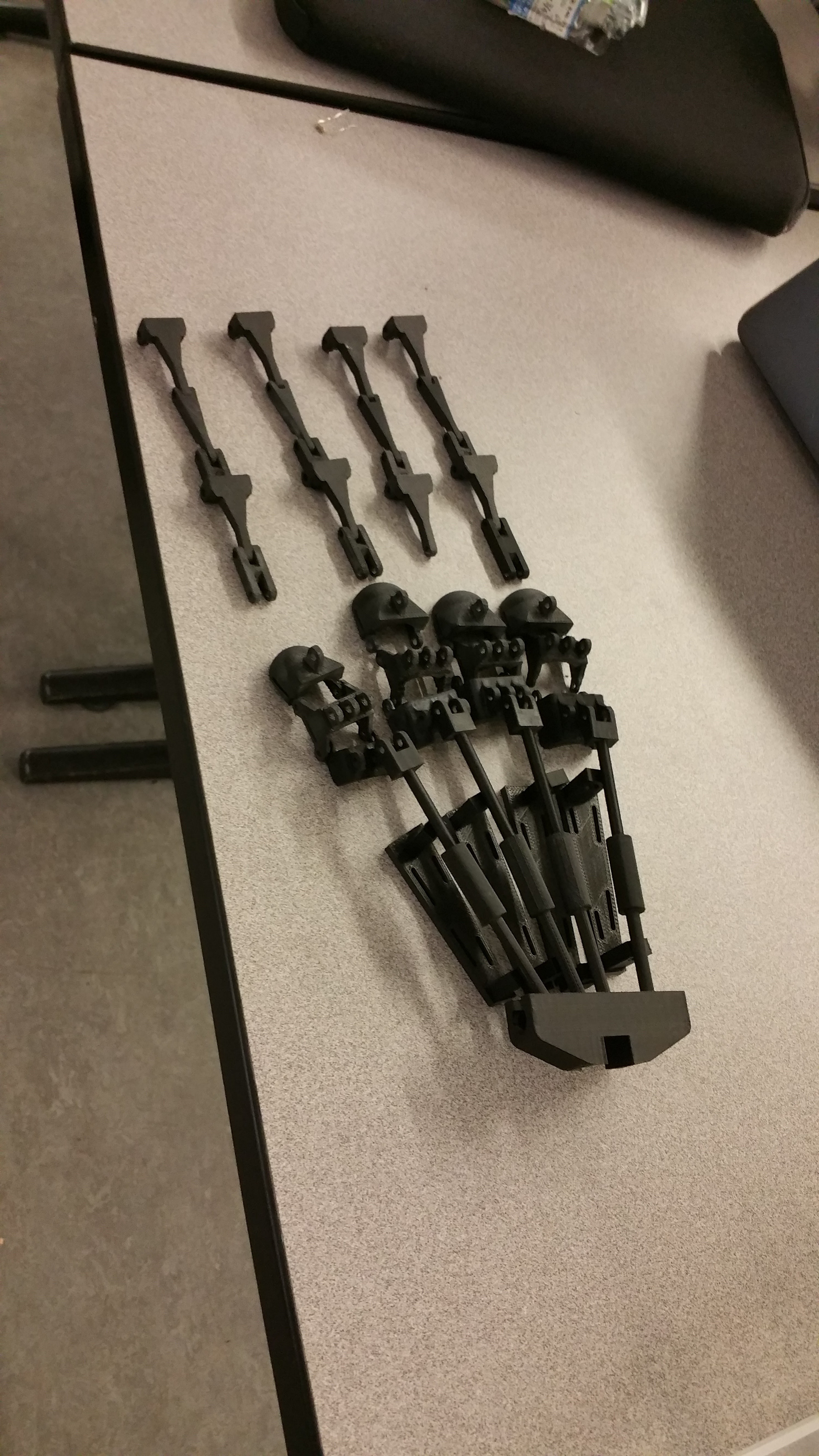
The first part that was assembled was the back of the hand
![]()
The 4 parts were woven using thin elastic band bought from Michael's. The straps' ends had velcro sewed on so that we can strap it on to our hands.
![]()
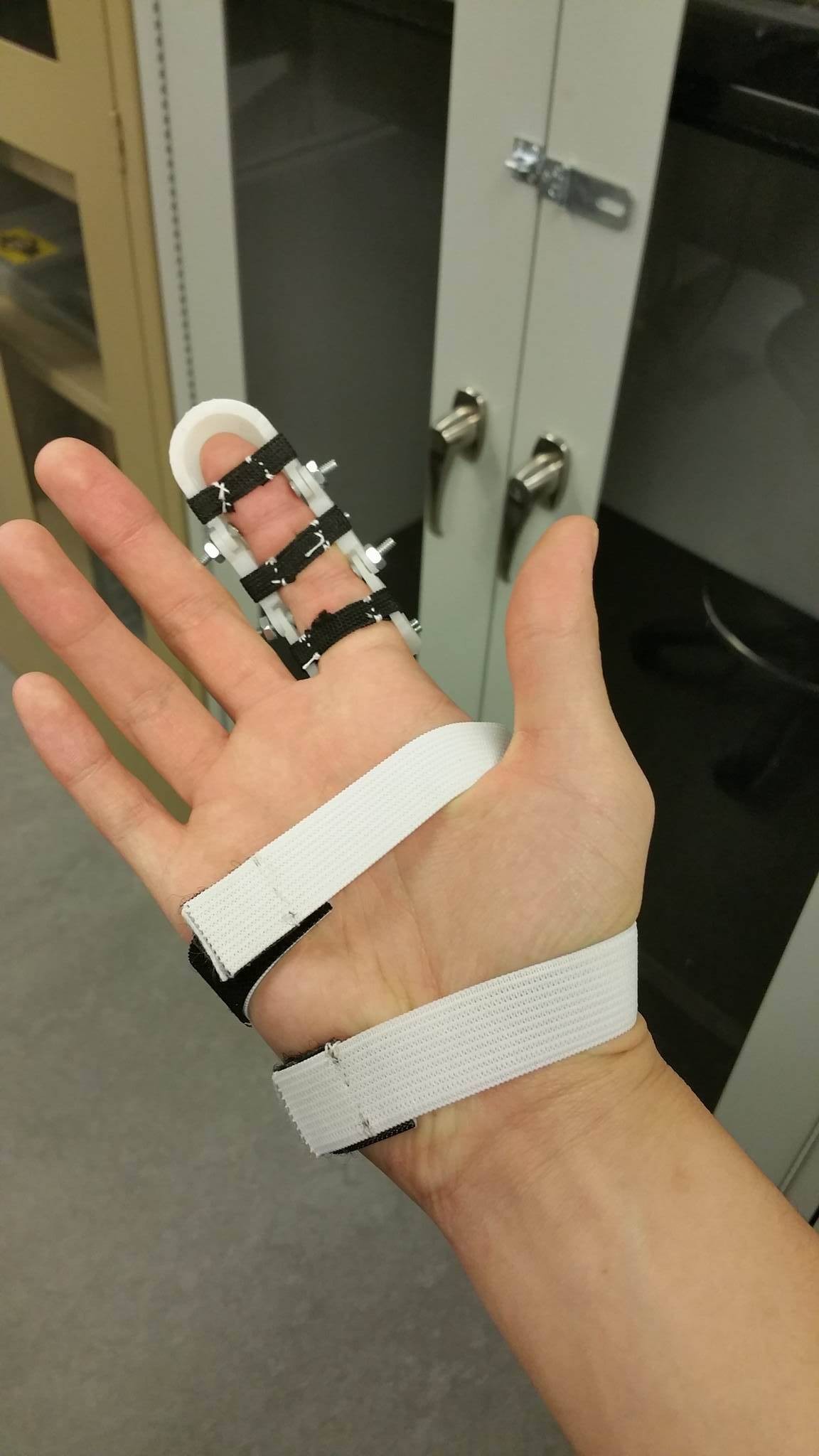
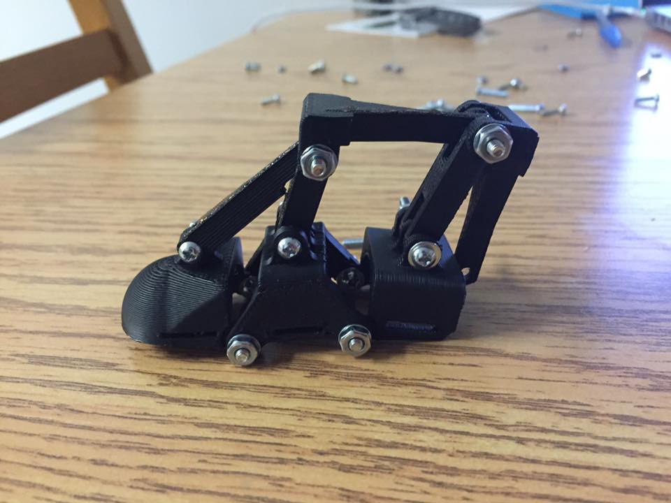
The next components that was assembled was one of the finger. The holes that we put on our design was 4-40 screws. As seem above, small strap of elastic was used to make the belt for the finger assembly.
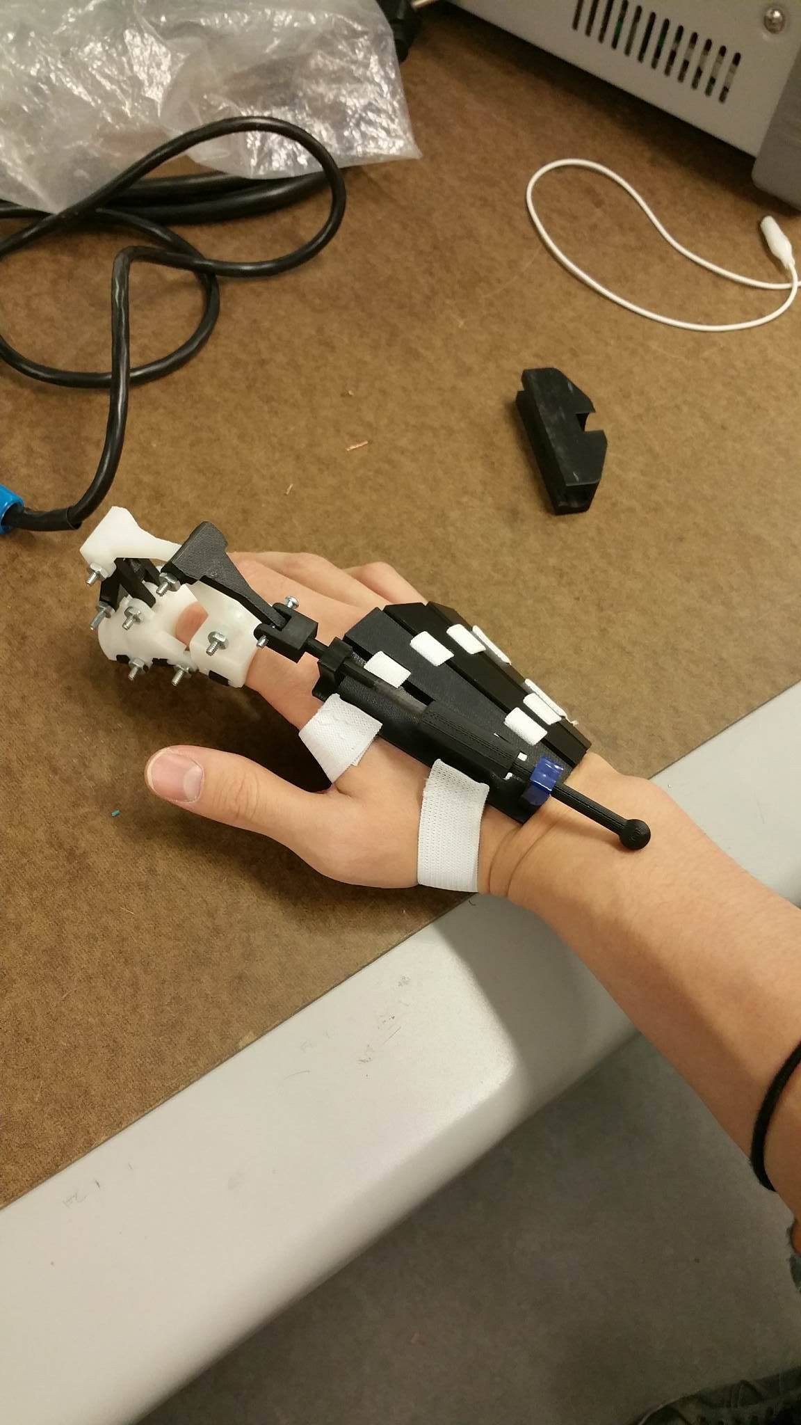
Along with that, we were able to assemble the differential rods that are on back of the hand. The mind-assembly looks something like this:
![]()
After the assembly was somewhat done, we worked on making the H-Bridge for controlling the linear actuator.
For those people that is not familiar with H-Bridge, it is used to control the linear actuator. Linear actuators extend and retract by changing the polarity on the two leads. However, since the user cannot change the pin orientation every time that they want to extend or retract the actuator, an H-Bridge must be implemented.
The schematics that we used was from this website (so all the credit to this guy):
http://www.bristolwatch.com/ele/h_bridge.htm
The two digital pins turn on the two transistors which allows the 12v to flow.
After the meting today, our prototype was one step closer to being reality.
![]()
![]()
-
First Whole Print and Improvements
09/23/2016 at 01:21 • 0 commentsThe first design was 3-D printed by the printer form our school. The total print costed us 123 CAD.
The material that was used to print was PC-ABS, which has a decent strength, and also allowed a very accurate print.
We definitely expected some mechanical flaws of our design since this is our first official print, but we faced a lot more failures, probably more than we expected.
First of all, we realized that our finger parts were poorly tolerenced, and poorly mated, but we did not see the flaw until it was printed out.
![]()
As you can see, the two holes were supposed to go on top of each other, so that the holes can be threaded through with some screws and bolts, but since the parts were not mated properly, it did not fit at all.
However, we decided to just try building it and see how it looks.
From this
![]()
To this
![]()
The shape is coming out and we are really liking how its turned out.
So over this week, we are going to print the fixed parts and hopefully can get the hand assembled by Sunday or Monday.
Some other members will be working on the electrical control, specifically the H-Bridge and others will be playing around with the Myo armband and Arduino.
-
Extending the Finger
09/20/2016 at 02:50 • 0 commentsOnce a working finger prototype was developed, we began considering how the four fingers could come together into a fully functioning hand assembly.
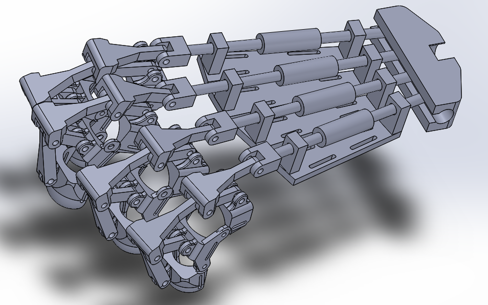
The goal of the remainder of the hand is simply to transfer force from the linear actuator at the wrist to the fingers. Firstly, a support plate had to be designed which would rest on the back of the hand and support the force transfer system.
Since there would be no one surface that would fit every user's hand, the back-of-hand plate was segmented into four components in a way that mimics the human palm's four metacarpal bones.
Springs were added to the inside of four force transfer rods to allow for movement of the fingers even after one finger has completed its movement.
Finally, a slot to translate the force from the linear actuator into each of the rods was implemented.
The whole system was designed and put into one big assembly that looks like this:
Finally a design we could show of :)![]()
-
Fixing the Fatal Flaws
09/12/2016 at 15:25 • 0 commentsAfter all of the new knowledge we had learned from our failure from the first test print, we fixed up the outer joint design, increased the quality of the 3D printing, and overall increased the quality of the design of the finger. We also added screws and bolts at all of the joints.
![]()
-
First Test Print!
09/12/2016 at 15:06 • 0 commentsThe CAD model was printed using a Da Vinci 2.0A 3D printer. As expected, our first test print was not such a good one. Due to factors such as poor print quality, bad joint design, and improper layering when positioned in the 3D printing software, our first prototype crumbled fairly quickly. Also there were no tolerances made for our moving parts such as our 4-Bar links and the outer joints, so many thinks didn't fit properly.
Below is a video of initial print in action (notice the broken joint).
-
Added 4-Bar Linkage to Design
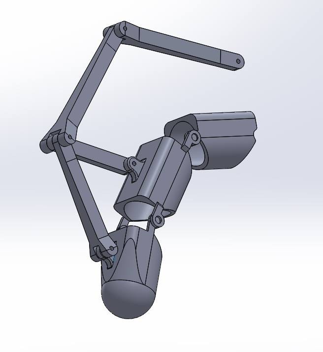
09/12/2016 at 14:45 • 0 commentsAfter doing some rough calculations for 4-Bar linkages, it was implemented in the SolidWorks design below.
![]()
-
First Mechanical Design!
09/12/2016 at 14:42 • 1 commentAfter few sessions of brainstorming and sketching the mechanical design, our group was able to create a CAD drawing of the finger portion of the exoskeleton. My (Chad) finger’s dimension were used to dimension the fingers. The CAD was designed with a table, with varying measurements for each finger, which allowed us to create 4 finger models with different dimensions (excluding the thumb) at the same time.
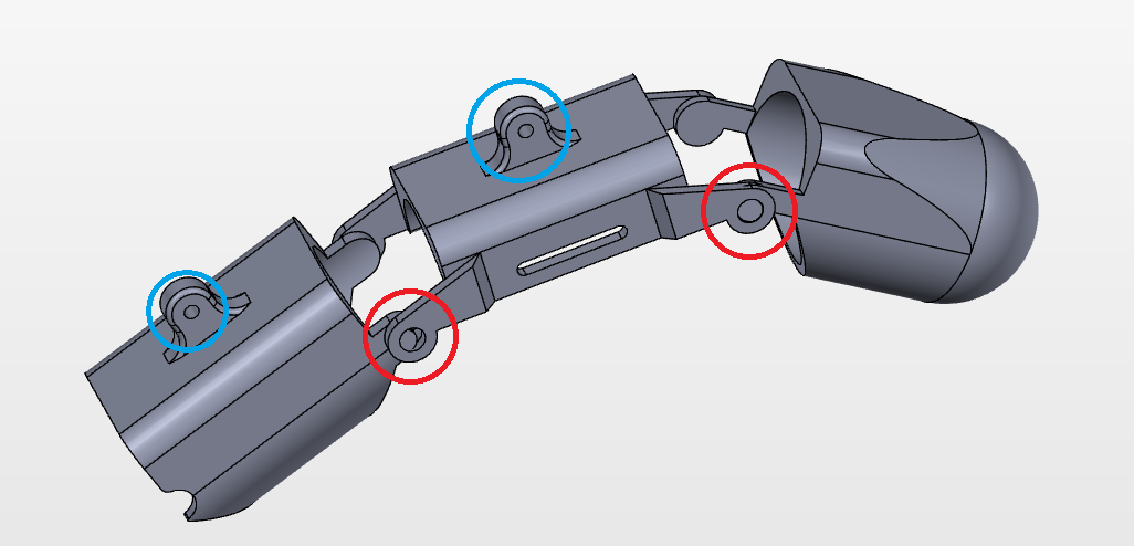
The three sections of the finger exoskeleton are connected using an outer joint (indicated by red circle below). It is using a “snapping” method to connect the sections together. This was necessary because the axis of rotation needs to be on the same part as the finger. The design that we created allowed for an “invisible” rod to go through the finger that allowed the skeleton to move like the fingers.
The two sections had connectors (indicated by blue circles below) for connecting the 4-bar linkages later on.
Below is a picture of our first finger assembly in solidworks.
![]()
-
Engineering Sketches of Desired Actuation Method
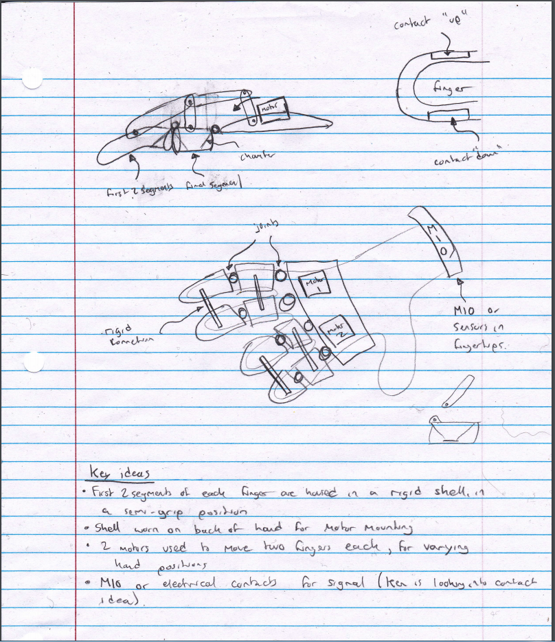
09/12/2016 at 14:29 • 0 commentsWe were initially attempting to control 2 fingers at a time with one actuator alongside a 4-bar linkage actuation design. We also brainstormed a good joint design that's ergonomic for the user to move their finger in (we later realize that we failed at this intention). We ended up deciding that we were going to use the Myo (not MIO) armband for the EMG signal processing for ease of use and then later on adapt electrodes for signal processing.
Below demonstrates an example of the engineering sketch that we chose as our final actuation path we chose to take.
![]()
-
Deciding How to Actuate our Exoskeleton
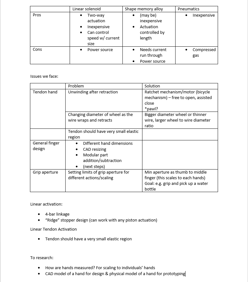
09/12/2016 at 14:20 • 0 commentsThe first challenge was to find the right method of actuation. Some of the actuation method that were considered were solenoids, pneumatics, hydraulics, shape memory alloys, linear actuator with 4 bar linkages, and tendons. It was very difficult to find solenoids and pneumatic or hydraulic pumps that were small but powerful enough for hand actuation. Therefore, our group’s options narrowed down to 4 bar linkages or tendons.
At first, tendons seemed more reasonable to use because of its light weight. Also, tendon is how our hands are moved naturally, therefore it seemed very intuitive to use the tendon method. However, designing a component that will organize all the wires on the palm was extremely difficult. Our major source of prototyping method is the 3-D printer and laser cutter, but a palm plate made out of those materials will be very rigid and will prevent the user’s hand to bend around an object. Also, winding up wires to control the movement is a lot more difficult than controlling a linear actuator.
Therefore, using 4 bar linkages with linear actuator was set to be the method of actuation of our choosing. For the first prototype we are building, we thought it was a good idea to choose a method that is easier to control, easier to manufacture with our given resources, and easier to design compared to the tendon method. The cons of this method is that it is bulkier and it is heavier considering the usage of a linear actuator. However, instead of trying to make a good project from the start, we thought we could instead improve our design by first designing a prototype.
Below is the chart that used to come up with our final actuation method.
![]()
 Chad Paik