danjovic
-
Yet Tweaking
05/22/2018 at 01:18 • 0 commentsReplaced the "DAC" resistors with an association to get more precision. The association values have been calculated using an online tool (link)
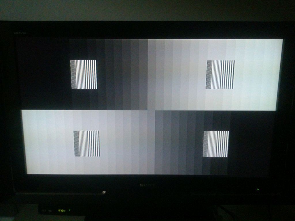
Desired Value (Ohms) Association (Ohms) 3131 3k3 // 56K 1563 1K + 560 780 390 + 390 390 390 195 390 // 390 211 220 // 5k6 187 220 // 1k2 Nevertheless, the shades yet were not gradual at the center. After some tweaking adding resistors in parallel I've managed to figure out which resistor in the network was disturbing the "linearity" of the output. It happened that to be the 195 Ohms resistor association. Few experiments later I have added a 120 Ohm resistor in parallel thus resulting in 75 ohms (sic) but I've managed to get a good image.

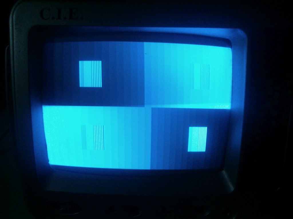
Linear gradients on a 46" LCD TV set Linear gradients on a 5" B&W CRT TV set It didn't occurred to me at the moment but maybe there is one bit flipped either in software or in the circuit.
Series and parallel association of resistors -
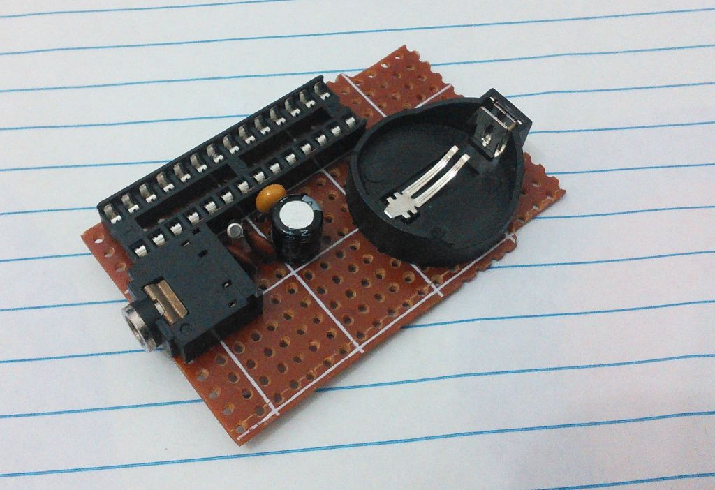
Prototype: Assembly finished and first tests
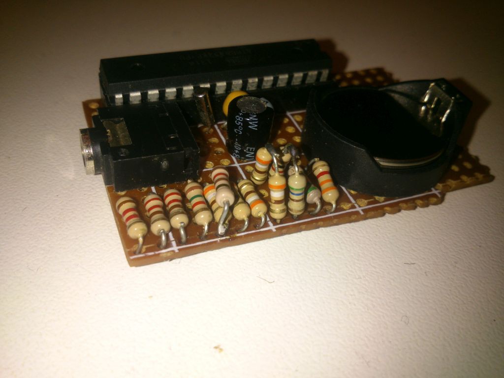
05/09/2018 at 03:56 • 0 commentsFinished assembling the prototype, but first fixed another issue that was a missing pull up resistor on RESET pin. Completely forgot about it because the first prototype, based on ATTiny85 had the RESET pin configured as IO thus such resistor was not required.
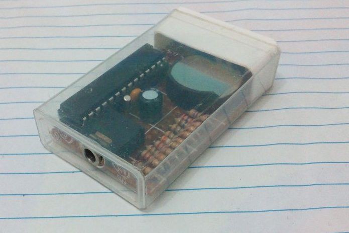
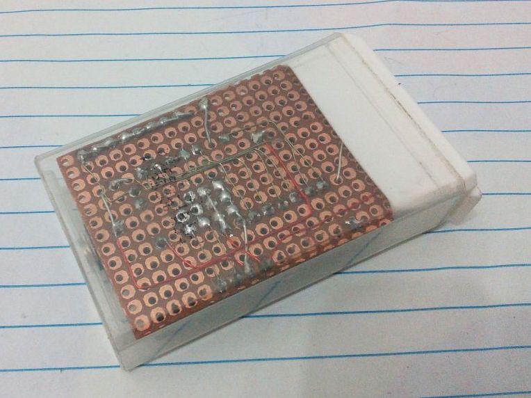
Prototype already assembled on the Tic Tac mint box Rear view of the prototype. Using enamel wire for most connections. Noticed a couple of issues that might be, however, connected. First is the signal voltage that is 1.2Volts peak to peak with open circuit and 0.8 when terminated with 75 ohms resistor. The second issue is that the bars at the middle of the screen are somewhat scrambled again.
Working with a HD TV set It will be necessary to perform a more acurate measurement of Voh and Vol on the circuit and this will probably influence the value of the resistors.
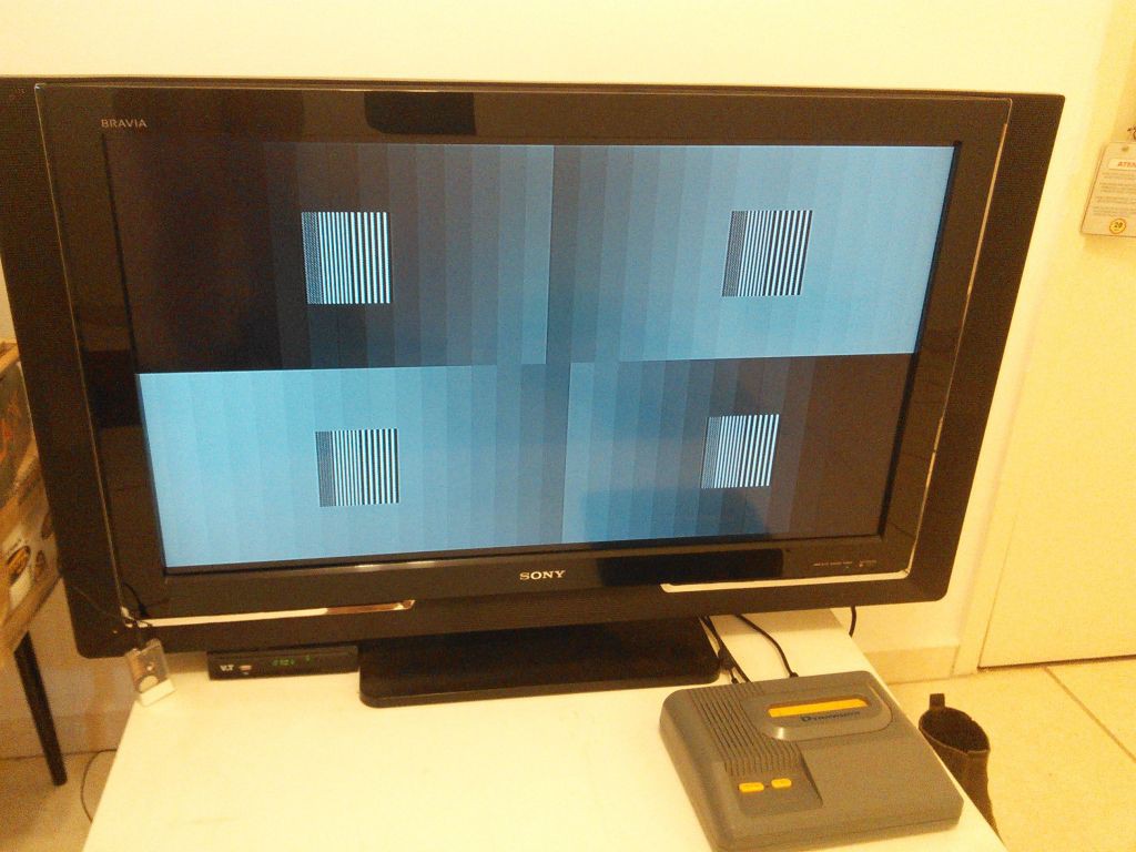
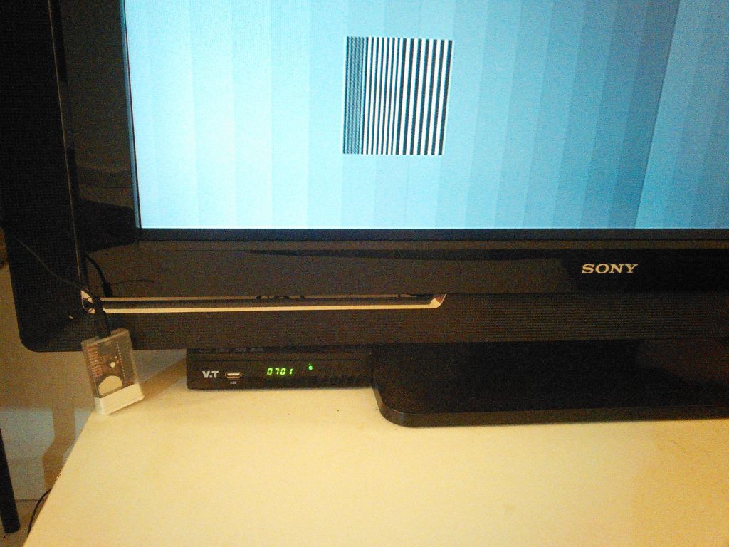
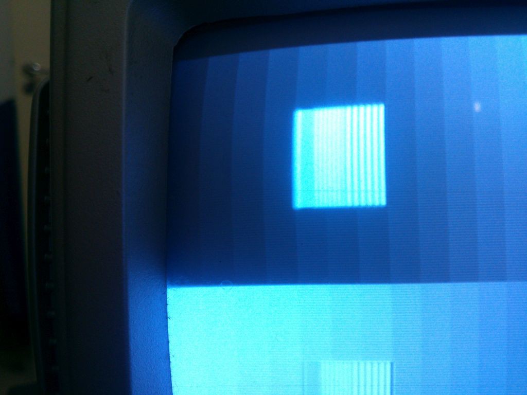
The resolution pattern was very clear on this TV set, as the thinnest line pairs could be distinguished. It demonstrates that this TV set analog circuits can deal with video content compatible with its native resolution (1360 pixels wide). Worth to remember that the test pattern is equivalent to a resolution of 850 pixels.
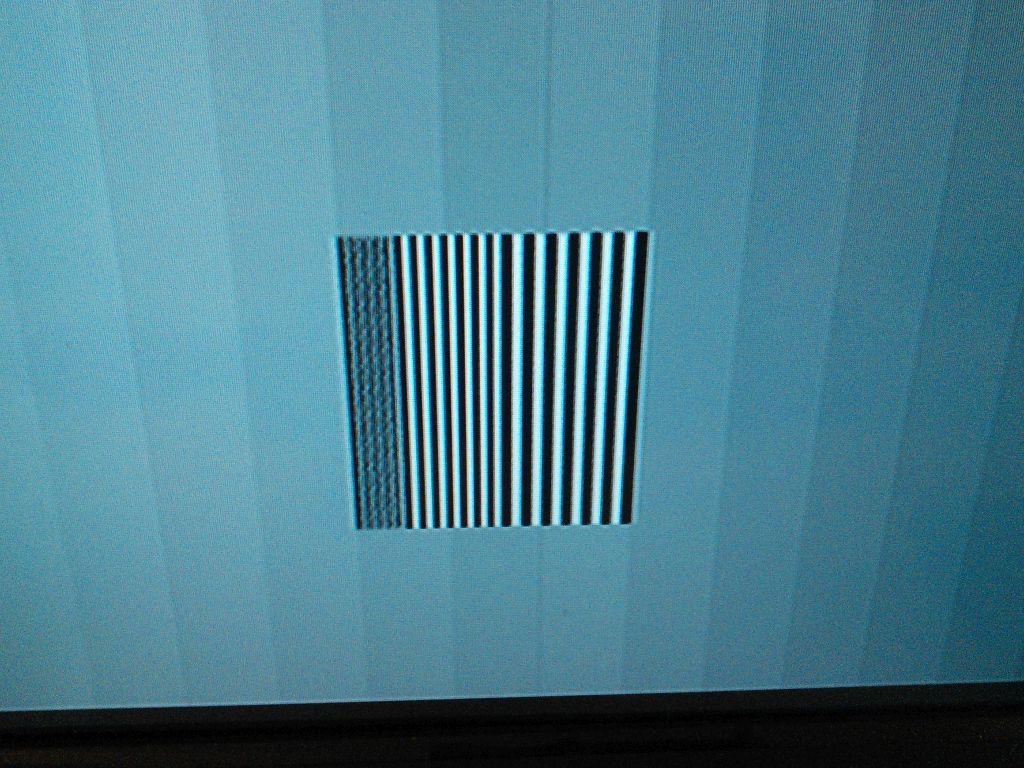
Resolution pattern. Highest resolution line pairs clearly noticeable Detail of the resolution pattern -
Browned Out!
05/09/2018 at 02:05 • 0 commentsAfter changing the platform for this project to ATMegaxx8 and used an Arduino board to finally debug my code I have started to assemble the prototype version in perfboard. I have decided to go with prudence and wired only the power and crystal lanes so I could check that such "infrastructure" of my board was ok.
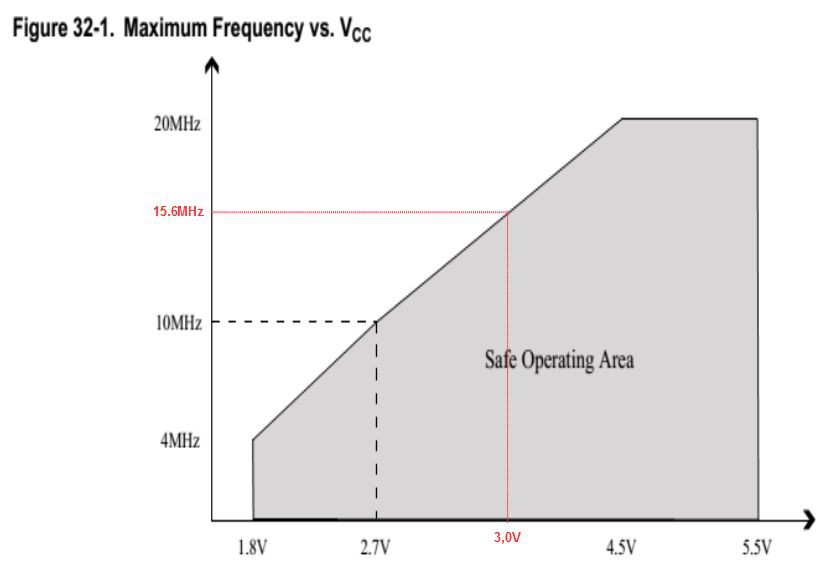
Looking at the datasheet the maximum operatinf frequency should be around 15.6MHz for a supply votage of down to 3,0Volts which is close enough to the frequency that the microprocessor should operate.
The first tests running with the CR2025 battery showed that despite there the clock is being generated on the crystal leads, the completely dead.
Tested again with 5.0Volts and the circuit was OK.. This was a bad signal! What have I missed?
After struggling some time with the idea of changing to a larger Tic Tac box or either using a lower frequency crystal I have remembered to check if the Brown Out Detection was active, and which would be its treshold.
The reading of the fuse bits showed that the brown out was set to 2.7Volts, which should not pose a problem as the battery voltage was about 3.0Volts when tested. Nevertheless I have reprogrammed the fuses to disable the brown out detection and this time the circuit started to generate the signals just as expected.
-
Anything Redeeming
05/05/2018 at 03:09 • 0 commentsAfter some work on the code I have finally managed to make it work as expected!
It is working now! The color of the bar right after the resolution pattern is correct now The last bug to fall was the color of the bar right after the resolution pattern. It was a register that should be updated but I was out of spare cycles.
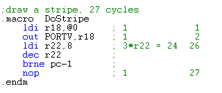
Then I have abandoned the use of a table and a pointer to pick up the color of the current stripe; instead I have used a macro with a parameter which happens to be the color and repeated such macro 31 times along the line.
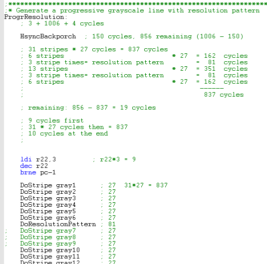
Macro used to generate a single strip Then, at the lines which contain the resolution pattern it gets easy to replace some stripes for the pattern simply by commenting the macro. As long as the cycle count matches the multiples of the width of a stripe everything gets fine!
Generating a line of progressive color stripes -
Board for ATMegaxx8 version
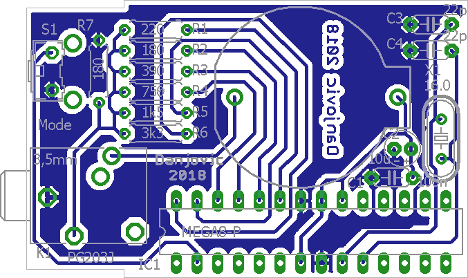
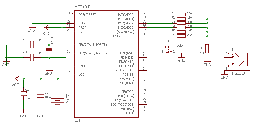
05/04/2018 at 22:18 • 0 commentsNew schematic and board for ATMegaxx8 (48/88/168/328), still in a mint case with provision for a button to allow change the pattern on screen.
Board for ATMegaxx8 still in Tic Tac mint case New schematic for ATMegaxx8 -
Getting things right
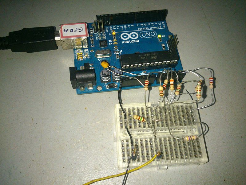
05/04/2018 at 04:33 • 0 commentsAfter failing with using the internal oscillator I have switched to Arduino Board as a prototyping platform.
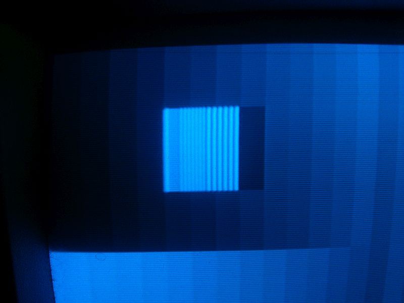
Moved to ATMega328 platform (Arduino UNO Board) First thing noticed is that the image is perfectly stable using the crystal.
Image stable when using the crystal oscillator The correction of the grayscale shades after the resolution test pattern were another story. I needed a spare clock cycle to add 3 to the color pointer, then it was necessary to move one instruction some memory positions before and thus save a cycle. some tweak is still necessary, though to get the correct stripe colour after the resolution line pairs.
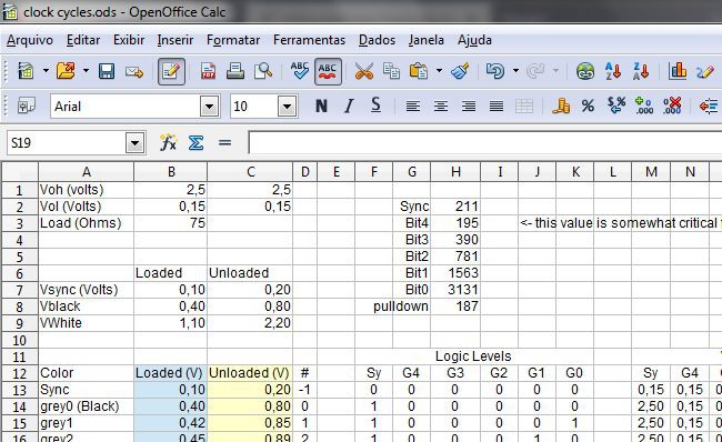
I have produced a spreadsheet that can calculate all the resistors based on values of VOH, VOL and the sync voltage level when the 75ohm load is attached (e.g. 0,15V). I have a good link on how to solve a matrix equation with rectangular matrices using standard functions of a modern spreadsheet program. No Scilab necessary!
Resistors can be mathemagically calculated The spreadsheet resulted some values and I have used the most close value available in my parts bin. HOWEVER, I have noticed that the value for the resistors on most significant bits are somewhat critical.
for instance the calculated and used values were:
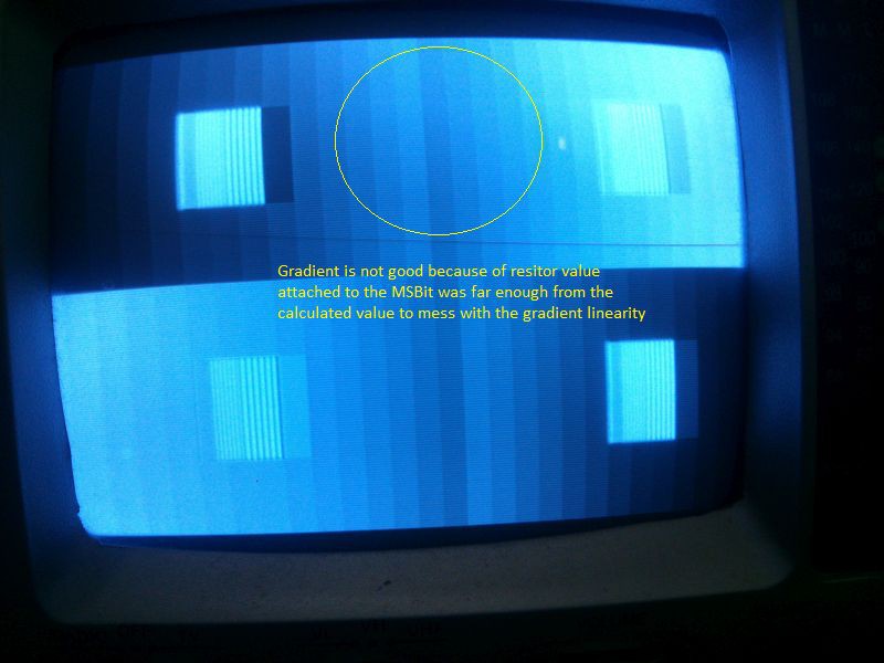
Resistor Calculated (Ohms) Used (Ohms) R Sync 211 220 R Bit 4 195 220 R Bit 3 390 390 R Bit 2 781 750 (1k5//1k5) R Bit 1 1563 1K5 R Bit 0 3131 3170 (2k7+470) R Pulldown 187 150 I have lost some time trying to figure out why I couldn't have a good linear (progressive) gradiend after the middle of the screen, and finally discovered that I should have used a value closer to 190 Ohm than the 220 Ohm I have used. At the end I have put another resistor in parallel so the equivalent resistance dropped to 180 Ohms (1k//220) and finally get a good gradient!
Gradient not OK due to a resistor value in MSB not so close from calculated The image with correct resistor value can be seen below
Nice gradient. Great image so far... Some work has yet to be done to correct the color stripe right after the last vertical line. But I am happy for now.
-
Failing miserably
05/03/2018 at 23:55 • 2 commentsThe ATTiny85 internal RC oscillator drifts so badly that it was not possible to have a good image.
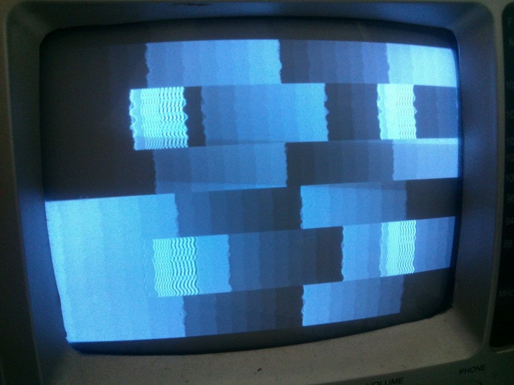
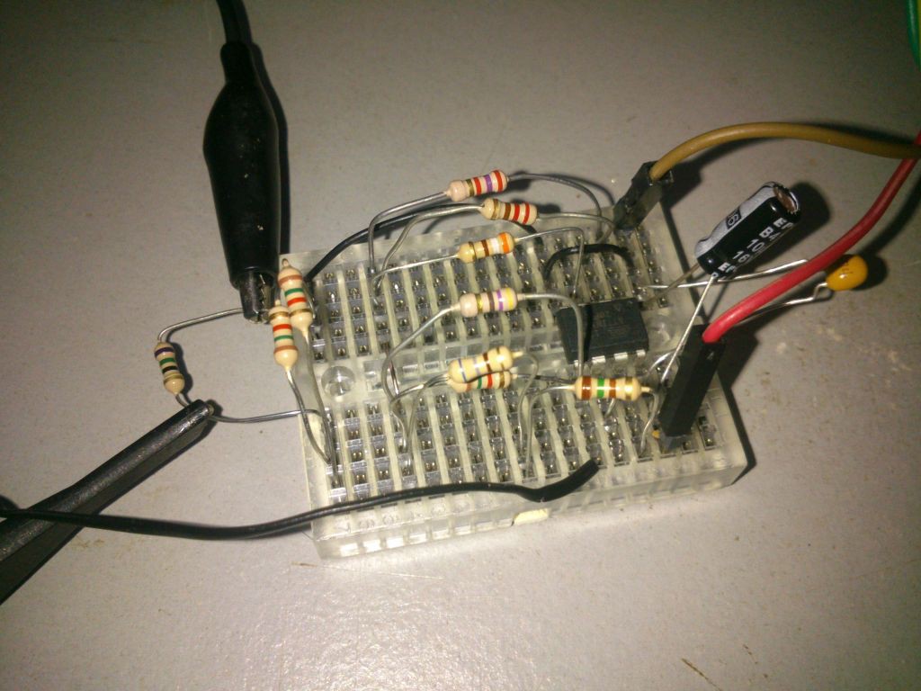
It was tested on two TV sets with similar result.Image on 5" BW TV set The circuit have been powered by both an arduino actig as a power supply and a battery (to eliminate any chance of power lane induced instability).
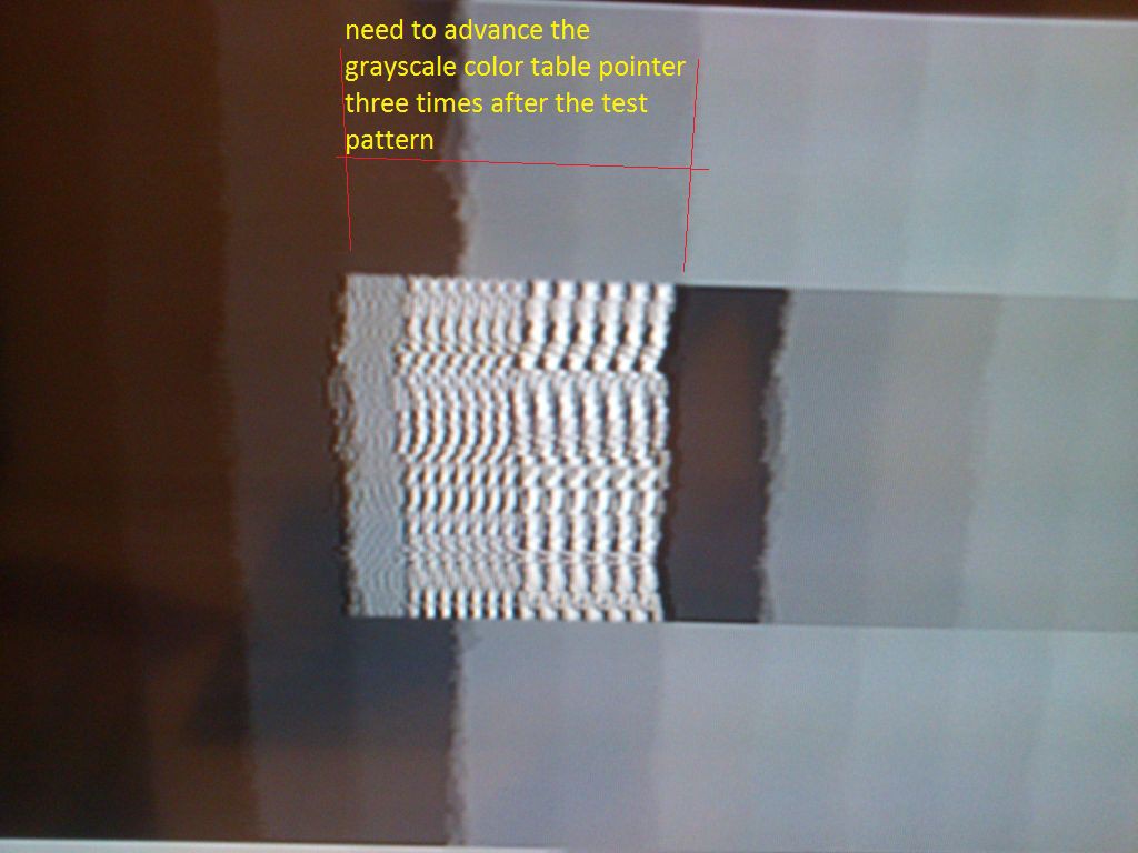
Assembled in Protoboard, with proper bypass capacitors on Vcc The code needs to be corrected (by advancing a pointer) to compensate for 3 missing shades of grey during resolution test pattern.
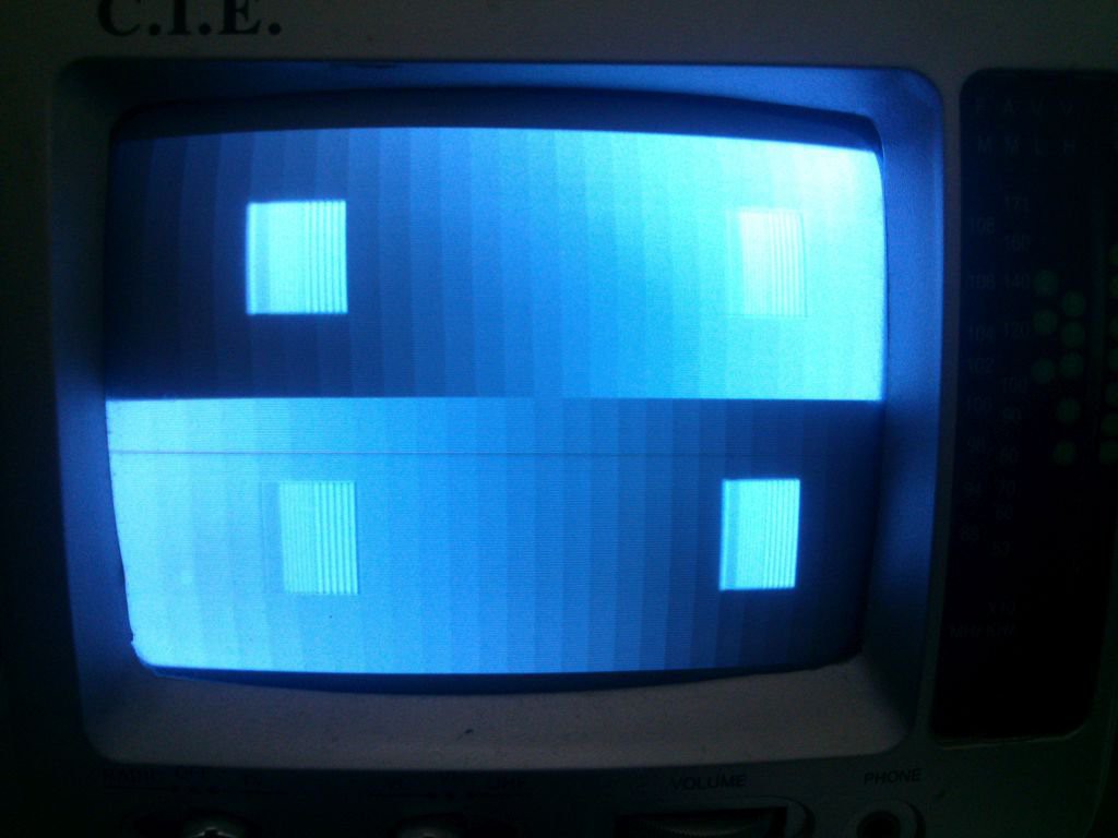
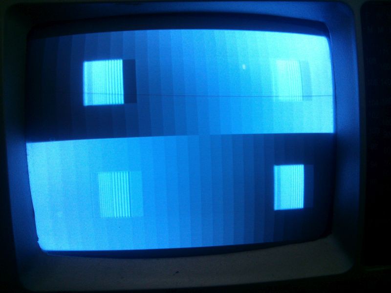
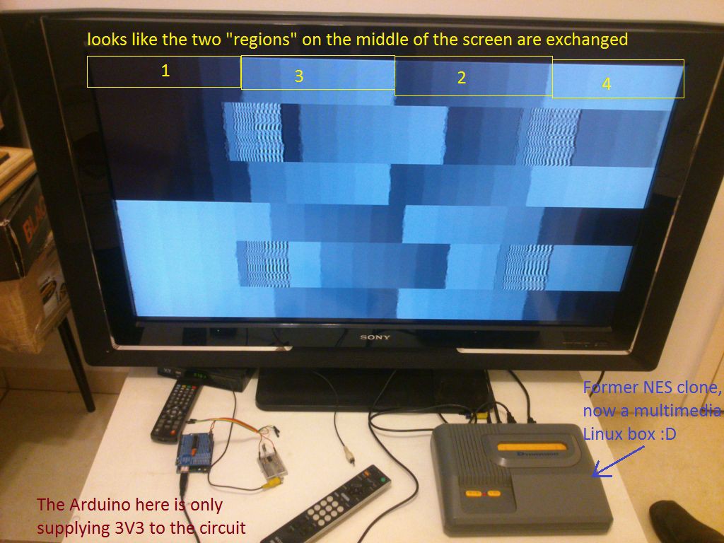
A pointer advance is needed here It looks like some of the resistors are corrected to the wrong pins as the grayscale is not progressive but rather it looks to have 4 distinct progressive patterns on the screen following the order 1 3 2 4 instead of 1 2 3 4.
"Zones" in screen. Incorrect assembly? -
Checking waveforms
05/03/2018 at 01:22 • 0 commentsFirst captured waveforms showed good results. It seems that everything is OK with the code.
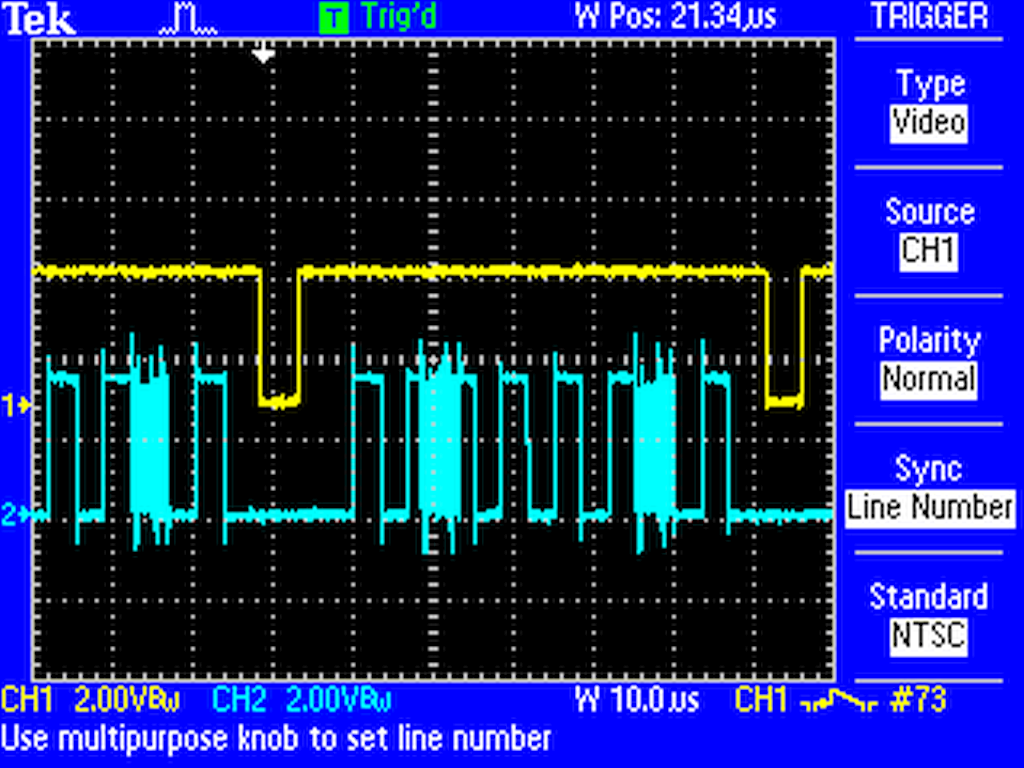
The vertical retrace interval seems to be OK, with the Horizontal Equalization lines as well as the vertical serration.
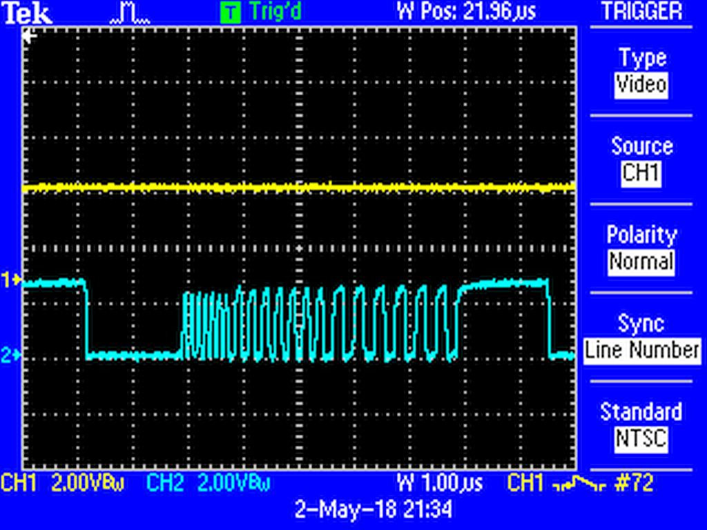
Vertical Sync Interval Serration Pulses The video content contains alongside with the grayscale a series of (black and white) line pairs with progressive spacing so it is possible to estimate the vertical resolution of the monitor. The thinnest pair of lines is only one clock cycle apart which means an equivalent resolution of about 800 pixels.
Horizontal resolution test content (line pairs) Detail of the resolution test content -
Operation at 3.3V, Oscillator accuracy
05/03/2018 at 01:03 • 0 commentsThe initial tests so far have been good. I needed to check:
- That the ATTiny85 could run at 16MHz on 3,3V - OK
- The accuracy of the internal oscillator - OK
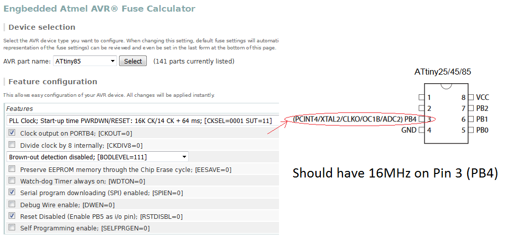
The accuracy was no so good as the measured frequency was 16.1MHz, but it is always possible to trim this later using a given EEPROM address that is loaded on the OSCCAL register on the beginning of the code.
It is necessary to program the fuses accordingly and to attach the scope at pin 3 to check the frequency.
Of course it is possible to use other methods that do not involve reprogramming of fuse bits.
-
Rendering
05/02/2018 at 14:25 • 0 commentsJust created a Python script to render the image as it should appear on TV screen.
# Project: 32 SOG
from PIL import Image

pixelclocks = 837

img = Image.new( 'RGB', (pixelclocks,pixelclocks*3/4), "black") # create a new black image
pixels = img.load() # create the pixel map

for y in range(img.size[1]/2):    # for every line
    x=0
    g=8
    for stripe in range(31):    # For every stripe
        for xx in range (27):
            pixels[x+xx,y]=(g,g,g)
        g=g+8
        x=x+27

for y in range(1+img.size[1]/2):    # for every line
    x=0
    g=256
    for stripe in range(31):    # For every stripe
        for xx in range (27):
            pixels[x+xx,y+img.size[1]/2]=(g,g,g)
        g=g-8
        x=x+27

img.show()
Which resulted in the following image
Noticed the height of the image was proportionally enlarged to fit in 3:4 format as it takes 400 lines on the screen.