3D Printed Robot Actuator
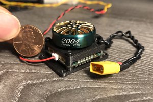
A high speed and high torque robotic actuator using low-cost brushless motors, custom controller, 3D printed parts and bearings.
A high speed and high torque robotic actuator using low-cost brushless motors, custom controller, 3D printed parts and bearings.
To make the experience fit your profile, pick a username and tell us what interests you.
We found and based on your interests.
Leg.zipRepaired Pack and go file for SEA legx-zip-compressed - 28.52 MB - 04/24/2019 at 16:48 |
|
|
WS3.cywrk.Archive02.zipPSOC4 Project files Hardware and software (code) files More CAN comms and move instructionsx-zip-compressed - 1.76 MB - 10/23/2018 at 16:28 |
|
|
tail.zipFull Tail CAD Files Inventor Pack and Gox-zip-compressed - 21.73 MB - 10/21/2018 at 17:40 |
|
|
6807_tail.stpFull Tail Step Filesstp - 3.93 MB - 10/21/2018 at 16:28 |
|
|
6908_LEG.stpFull Leg (with SAE) Step filesstp - 5.83 MB - 10/21/2018 at 16:23 |
|
41:1 Dual Disk, Single stage
27mm x 102dia QM4208 motor, 6809 Bearing
Before Cycloidal Gearboxes, I research Concentric Magneti Gearboxes.
I made an improvement on the current design by drastically reducing the flux path length and hence increasing the torque handling ability.
standard flux path
New flux path
1x Brushless motor with extended shaft (6mm Silver Steel)
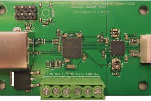
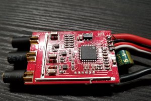
1x Custom Brushless Controller Board
2x AS5147 Absolute Position Boards
2x 6mm x 2.5mm Diametric Neodymium Magnet
12x 3D printed parts
16x 5x8x2.5 bearings
2x 6809 Bearings
5x 12x18x4
1x 6x10x3
8x 3mm dia x 30mm Silver Steel shaft
26 (or 13) 3/32" x 28mm Silver Steel shaft
26 (or 13) 1/8" x 16mm Brass tube (thin wall)
24x M3 bolts
10x M2 Bolts
3x PZT screws
1x M6 thin wall washer
1x 2mm dia x 11mm Silver Steel shaft
Suppliers
Favorite Makers
Create an account to leave a comment. Already have an account? Log In.
Hey, thanks for making such a great project public and taking the time to document it so well. All the best!
what did you use to design the gear profile? everything i find is using java or fusion360, both of which im not sure how to use (and i dont own fusion360)..
I estimated between 14-15kg with head/tail and batteries. Which seamed a bit "fat", so I'm making a simpler one with no SAE (springs) and a simple head and tail. It will be about 9-10kg.
Hi, your project is very, very nice. I'm considering to try it out. I was wondering, how large is your backlash? Why do you feel the need for two encoders? How will you use both in your control loop?
Also, I don't find the code for your mkr zero port (have you abandoned that front?)
Thanks a lot
I have 6 of these actuators and each one has a different backlash. Most have about 0.3mm @ 200mm. One has 0mm and one has 1mm @ 200mm. The main reason for the two absolute magnetic encoders is so I know where the motor is at power up and I know where the joint is at power up. There is no referencing or calibration required after each power up. This has to be done only once and the offsets stored in FLASH/EEPROM. I have two separate control loops. One for FOC of the motor-position and one PID loop for joint control. The output of the joint control just tells the motor the direction and speed/power.
I'm still working on the Arduino Zero/SAMD21 port. I'm slowly putting the individual feature code on git. It as taken a back seat while I work on the CAD and electronics.
Thanks for the very complete answers. I really hope to find time to try out you design and eventually collaborate. Do you think it could scale well to smaller scale motors/gears?
What modes and input signal types does the motor controller support? Step/Dir, position, torque etc.
At the moment it supports simple CAN packets (goto position) and UART commands (goto set position and move x degrees). I will add others types and more features as I need them.
Greetings again @Paul Gould I have private messaged you.
sir may i know what is the reduction ratio of this cycloidic gear box
So how long do the plastic (I guess cycloidal part) inner gears last under load???
Also what is the wear rate on the pins and would it be better to use pins with bearings.
I'm not sure. I've only really be testing at about 10Nm max, as this is all I need. The wear seems good so far. It is 3D printed ABS, don't expect too much. If you use bearings for the outer pins the diameter would be large, which means the reduction ratio is less and the pressure angle lower (torque produced in the wrong direction).
Hey Paul! Amazing project, I can´t stop reading all the instructions and logs...
I wanted to download all the files but unfortunately i am not able to download the file Legs.zip...
Is it offline?
Alex
Thanks, I have just uploaded Legs.zip it again, please try it now
Thanks its working now :)
Do you think 25% infill and 1.2mm wall thickness is enough for those parts?
Hi Alexander. I would suggest printing a single actuator first before you get to the leg. The SEA leg is complex. I've put it on hold while I develop a simpler quad ( See the tail project). I was trying to literally run before I learnt how to walk. With that said, if you can print the leg and learn more about it then maybe you can teach me somethings. It is open source after all.I use ABS 75-85% infill, 2-3 perimeters 0.4mm nozzle, 0.2mm layer height. Printed on a perforated board with a 3 layer raft, to stop warping. Also what controller are you planning on using?
Alright I already have started to print some parts in PLA with 25% infill, 4 perimeters and also 0.2mm layer height but I guess I should increase the infill.
I just wanted to build that leg and understand how it works :D I prefer to hold something in my hand...even if PLA is not very useful to print gears.
I was really mesmerized by that video testing the leg... It looks like it is by far the most promising leg for a robot dog.
Right now I really have no idea what controller to use. Some days ago I explored the OpenDog project by James Bruton (some people mentioned it before in the comments) and he is using the ODrive for his brushless motors.
I think this is okay for his project but it is way too expensive for a hobby project in my opinion...
What do you think about using an Arduino Mega like he did?
Today I was looking for the 5008 Multistar Elite Motor but it looks like they are not in stock anymore... while printing all the parts I wanted to solve the question about the controller...maybe there is a suitable open source solution?
I'm now using Gartt ML5010 300KV from gogo-rc.com They are good price and already have a small mounting plate. Controller information to come shortly.
Hey Paul!
Thanks for asking :)
I am really busy right now with our baby so my printer is not running right now ;)
Some parts are printed and I ordered the Gartt ML5010 motors since I couldn´t find any other motors with similar technical specs.
I can´t wait to test the leg!
Have you tested your brushless motor controller yet? The PCB looks fantastic!
Hi Paul, do you use the current for force/impedance control or do you use some extra sensing?
Hi, Can you tell me where you got the extended axle shafts? and motor mounts?
Thanks!
motor shafts are silver steel rob from https://mcjing.com.au/categorybrowser.aspx?categoryid=201 then cut to length and file a flat spot for the grub screw. The motor mount is the one that comes with the motor, it has just been attacked with a hacksaw. https://hackaday.io/project/157812-3d-printed-robot-actuator/log/146045-motor-modification I have just got some of these http://gogo-rc.com/store/index.php?route=product/product&product_id=3493&search=5010 which will not need the mount to be modified.
Thanks a lot Paul. Appreciate the links. My shafts have grooves in them for the circlips. I was wondering if you found shafts that had the groove in them already. I guess I could use collars or something on straight shafts.
Hi Perry, I have not found any off-the-shelf shafts that would suit what I need. You could make a groove with a saw or go to your local maker space and find someone with a lathe to make one for you.
Thanks again Paul. I have a lathe so I think I will have a go at it.
Hi Paul, I'd like to say that your contribution is remarkable - thank you! I've picked your actuator, among all others I've ever found, to test in my mobile robotic arm http://autom.world :) Fingers crossed for the Arduino version you work on!
I have just finished an anti-backlash version of this gearbox which I will upload in a few days time. I am still working on the Arduino version. I'm having trouble getting the SPI with DMAs working on the mkrzero. Maybe now I'm on holidays I will have some time to work it out. What sort of torque and speed are you aiming for on your joints?
Anti-backlash version, that's great Paul! I don't have experience with DMA, but I had some issues with mkrzero in the past - with interfacing IMU mpu-9250. Ported the code to both Nodemcu v3 and STM32 (blue pill) and worked without any issues. Maybe that will help you too. For the robot a 300kg/cm (30Nm) torque would be ideal, but for proof-of-concept 10Nm in sufficient. For speed 20-30RPM is enough.
Hi Jarek, I have finally got the SPI with DMAs working. Next is the ADC with DMA and RS485. I will then make a board. What voltage and current would your motors work at?
Clapping and fingers crosses! I have exactly the same motors as you.
Hi, just a quick question on the PCB design (specifically for the encoder). The schematic says "NF" which I know that not-fitted, but does this mean that you don't use any resistors at all? or what are the values for the resistor? I'm trying to make them in bulks and have PCB companies to assembly the board for me as well.
Also are the sizes for capacitors and resistors?
Thanks,
Jin
"NF" is "not fit" or no resistors. There are for optional extras. R1 (0 Ohms) is for 3V3 operation. R2 (0 Ohms) is needed if this is the last one in the SPI chain. R3 & R4 (1K) maybe needed for noise issues. All of the components are 0603 except R2 which is 0805
Hi! Saw your latest Youtube (subscribed) and I'm interested in using a version of your actuator design in the next Sixi robot. Our worst case at the base has a 20Nm holding torque. Can you advise us how to proceed, please? We'd love to collaborate.
Also we're interested in making a version that mimicks ulna rotation between wrist and elbow - so the input and output mounting brackets are coaxial to the rotation. Have you spent any time on that, and if so what are your thoughts?
The actuator is very rigid because it has both top and bottom housings and output shafts. I'm not sure how to make it rigid for ulna joints, I'll think about it. What angle of rotation do you need?
Hi Dan. Yes, we can collaborate. My suggested starting point is with the CAD. I'm using Autodesk Inventor. I think that you are using Fusion360. What format would you like the CAD in? Can you use the "pack and go" files that I have already uploaded?
fusion would be great. We probably have to make a gearbox at the shoulder that is stronger than your current model. What do you think of https://www.reddit.com/r/robotics/comments/9s134q/i_made_a_cycloidal_drive_for_cheap_robots_git/
?
I’d love to have a parametric way to make the gearbox I need, then follow your wiring recipe. In your experience, will this generator work for among the printable profiles? Is your package already parametric? Sorry I’m not up to speed yet.
You should be about to use the ipt files from the "pack and go" as per the instructions https://knowledge.autodesk.com/support/fusion-360/troubleshooting/caas/sfdcarticles/sfdcarticles/How-to-import-or-open-a-file-in-Autodesk-Fusion-360.html?_ga=2.119678216.1803184385.1540780561-1795324385.1536071126
I haven't used Fusion 360 but the script from the reddit should be useful.
I have created a parametric in inventor. I doesn't port well.
I’ve used a Rumba board until now (6steppers). Since you use dc im looking at odrive x3
Hi, Himanshu here from Youtube..
So, I have been thinking of this 4 legged robot and have observed that it is much better if the robot has a low Unsprung Mass.
In Automobiles:
Unsprung mass is: wheels and Suspension.
Sprung Mass is: Body, Engine, Transmission, Chassis.... (and all other things)
It is said Unsprung mass should be very less so that when the car moves and goes over bad roads the Sprung Mass stays at almost level and Unsprung mass only moves and passengers feel very less vibrations
Hence instead of attaching the lower leg directly to the motor.. a Pulley would be connected. this pulley belt will be going above the motor, present above the Hip joint motor. and belt will be having tension using a spring return system like in 3D printer Extruder.
This definitely increases complexity and difficulty in designing and simulating but.. MIT Cheetah 3 is based on this design improvement.
and the current Hub motor design is followed by ETH Zurich.
I don't know what Spot Mini does but they do it better, so if you find their method then do that.
Hi agenthimzz, I would like to have as little unspring mass as possible. It was a trade-off between total weight/complexity and unspring mass. The actuators were designed to be integrated into the joint and were made as compact as possible. I found that if I used 3D printed parts as "Fixed-Fixed Beam Moment" instead of the normal "Fixed-Free Beam Moment" they were much better. There were also designed to be linked together in various combinations to form robot arms or humanoid robots.
This design also meant that I could test my parallel linked series elastic actuator set-up.
Been following this project for a while, its huge for open source robotics!
Thanks AVR. I'm hoping that making the actuator work with Arduino will make it useful for more makers. I think that a combination of this and the "gear down for what" gearbox will make for a perfect system.
Beyond the challenge of it, why did you create a custom controller vs the oDrive? Do you see any issues with oDrive and your actuator design for mere mortals like me who would go that route?
I large part of it was to see if I could make it my own way. Mainly using Voltage FOC with a saddle lookup table on a CPU with no floating point. ( ~10 lines of FOC C code). I wanted full control over the actuator with room to grow as I learn more. The PSOC4 is my favorite uC/SOC, plus it has a little FPGA and easy CAN comms. I can connect any type of encoder up to it for motor and joint control. I didn't like the calibration set-up of oDrive (you have to reference every power-up). Using Voltage FOC motor control and dual magnetic encoders, I can tell where the motor and the joint is at any time. I am currently adding Series Elastic to the actuator. The FETs I use are very low R-on. The board also fit's my space requirement and I can make them with a simple soldering iron.
oDrive are a great idea (I've never used one) and they will add more features over time. There is a large community following and they are currently working on absolute encoders, CAN comms, a smaller single axis board and more control schemes. The oDrive CPU is very powerful and has room to do some much more. YOu can modify the code to suit your needs.
The PSOC4 is not an easy CPU/SOC system to learn. Half the work is done in the CPU and half in the FPGA section. Debugging errors can be a pain.
I started looking at porting the design over to a SAM D21 (Arduino Zero) but I didn't like the SPI. I will work more on this in the future as having an Arduino brushless actuator controller will make the project more accessible to more makers.
I hope this helps.
Great work! I like the compactness of the gearbox system.
Didn't have much luck with this concept. Direct drive is a bit too power hungry. Modern brushless servos can do pretty incredible things for a lot less money.
Hi lion, this design is not for everyone. It's not direct drive, the cycloidal gearbox is 25:1 reduction. The cost is about $150 (the time is huge). The aim is 20Nm (200kg-cm), with speed of 0.05sec/60deg (testing required). The backlash is extremely low and it also backdriveable. I created this because I couldn't find a servo that suited me, if you know some good servos please let me know.
Become a member to follow this project and never miss any updates


 Anthrobotics
 Christopher Xu
Hi Paul, I sent a note to the application. i need to have some targeted iimprovement on this design for prosthetic elbow design. i am a father a child who needs one, i need to work or get some work done on this specific design idea.. thank you