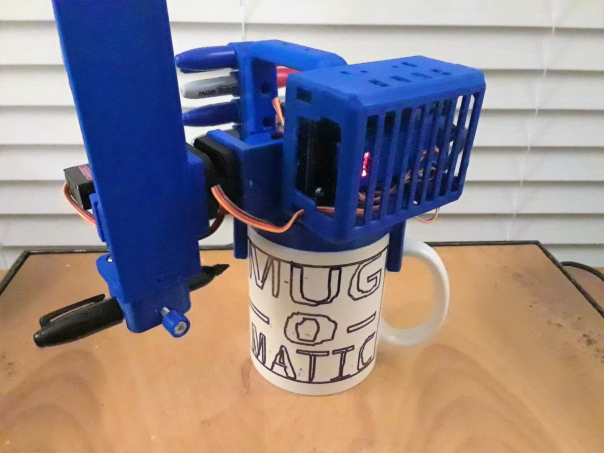
This instruction set will start with physical assembly of the standard Mug-O-Matic, then programming the arduino, and finally preparing custom mug drawings for gcode.
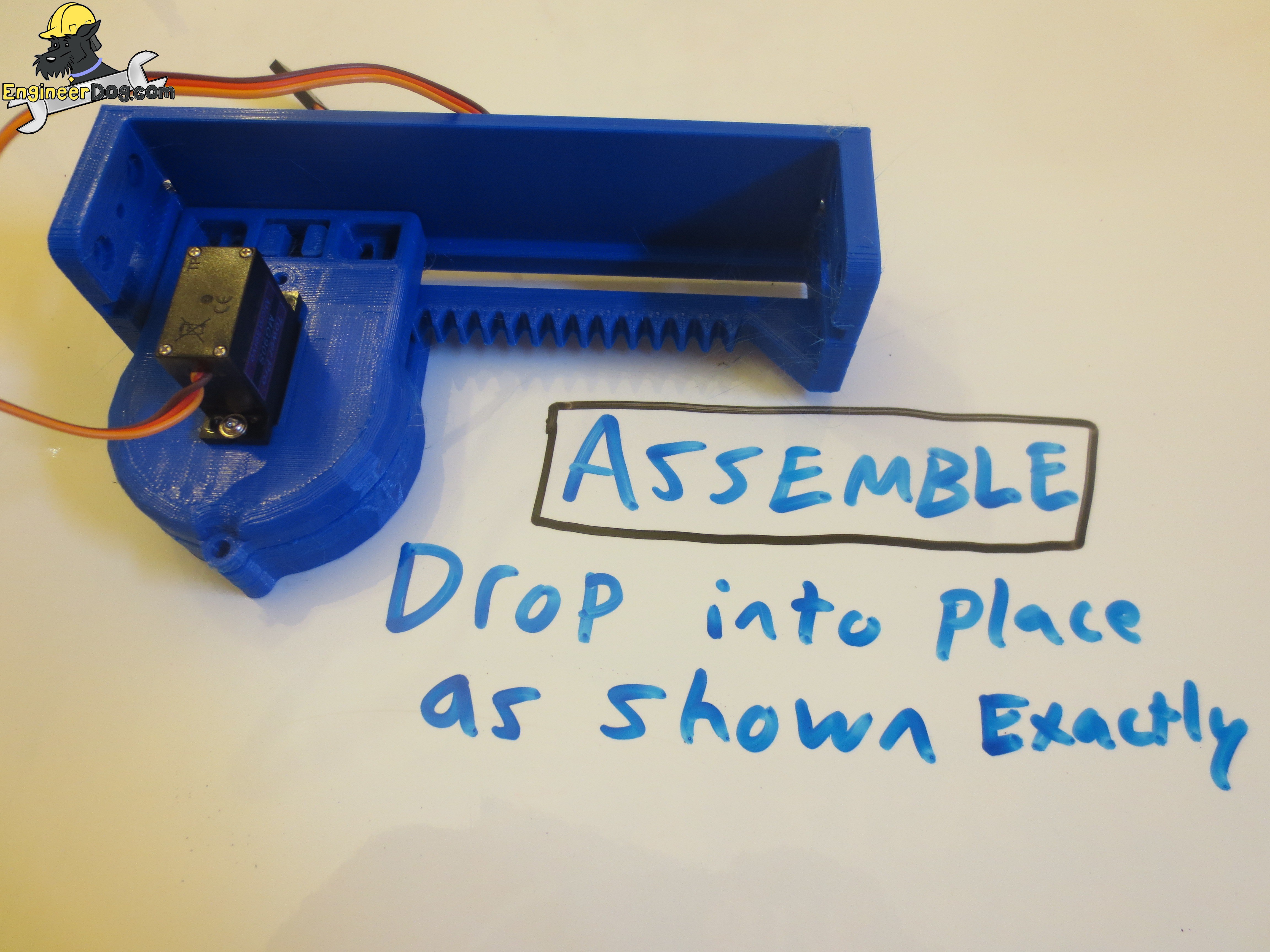
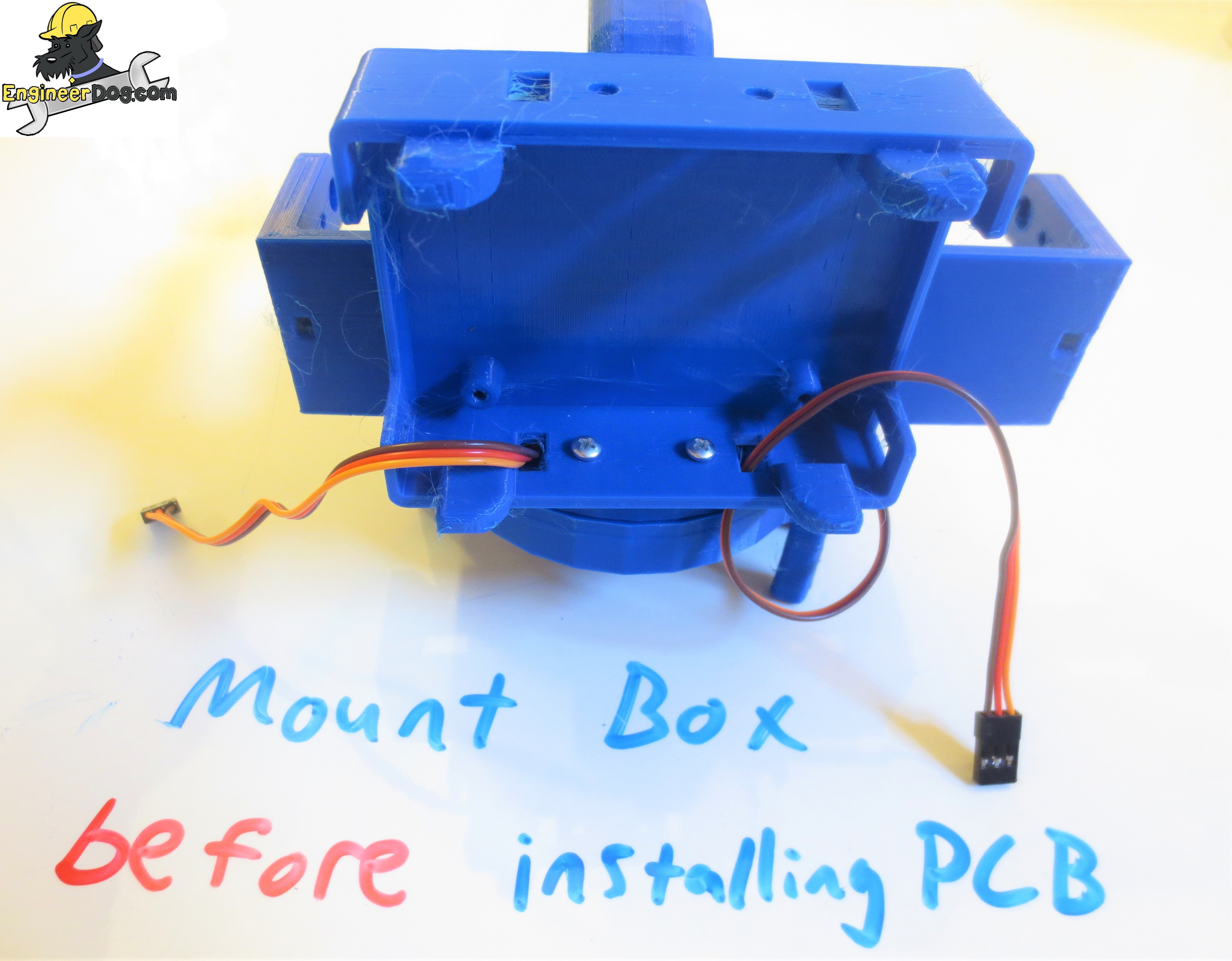
Order of operations and following the instructions as shown here is very important for this build.
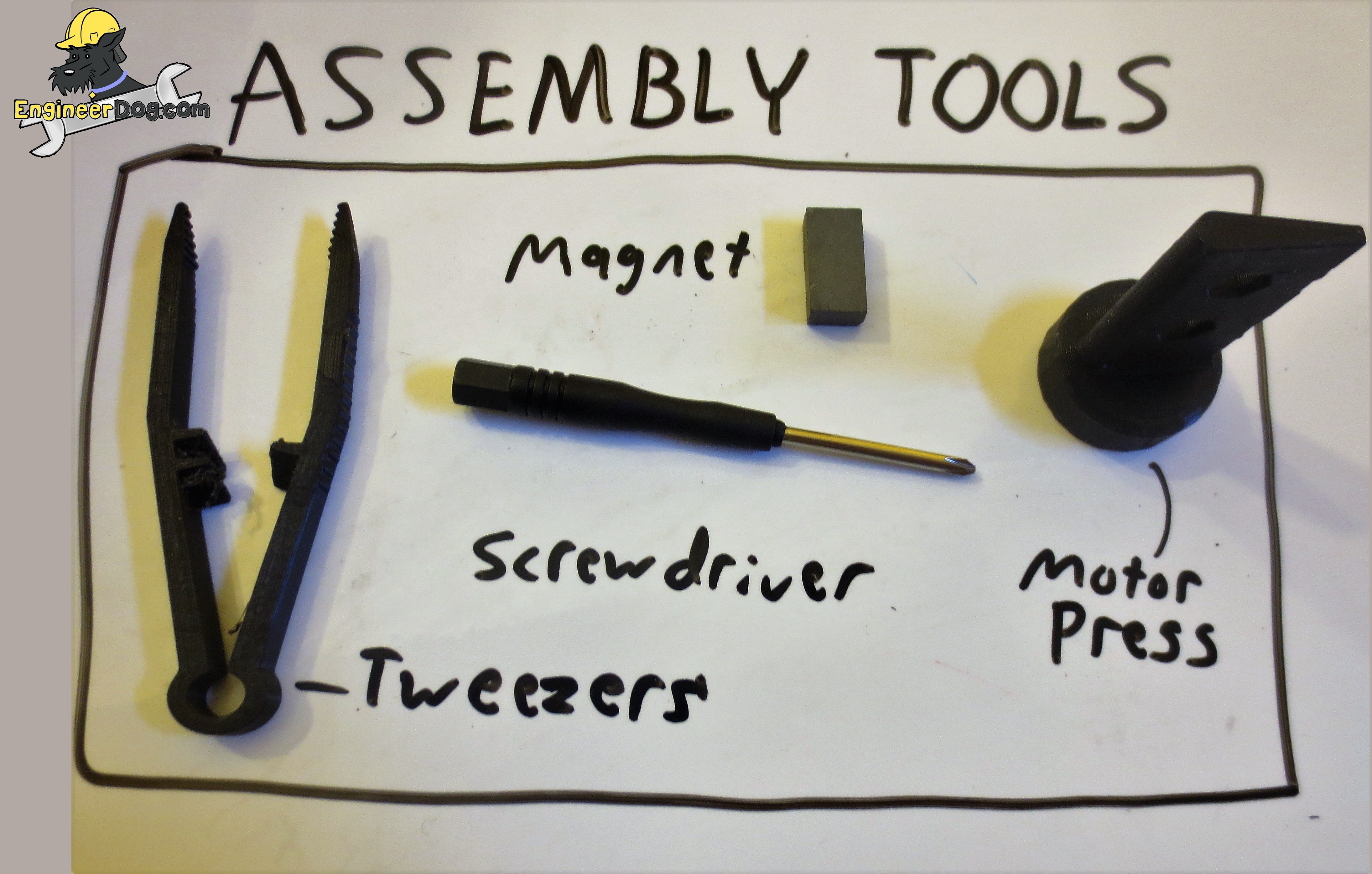
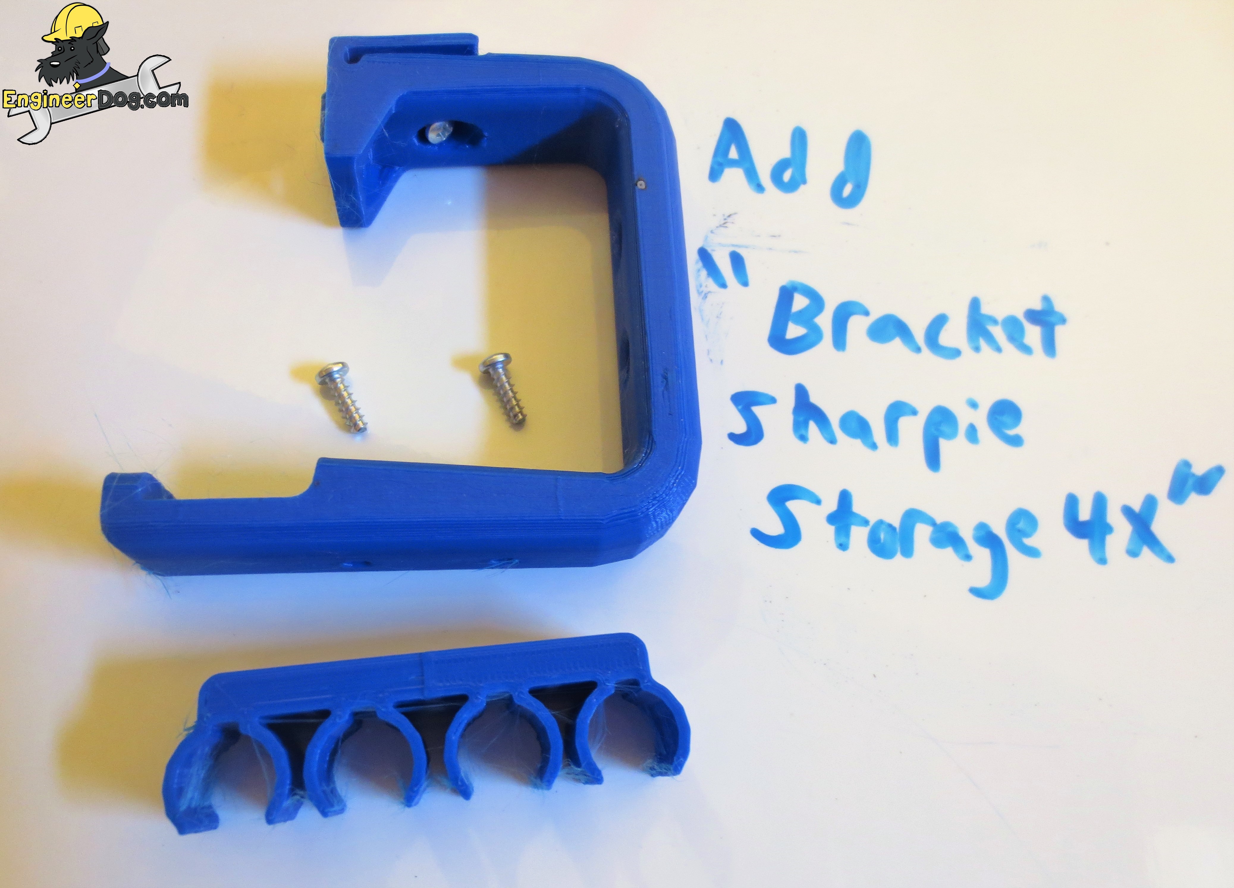
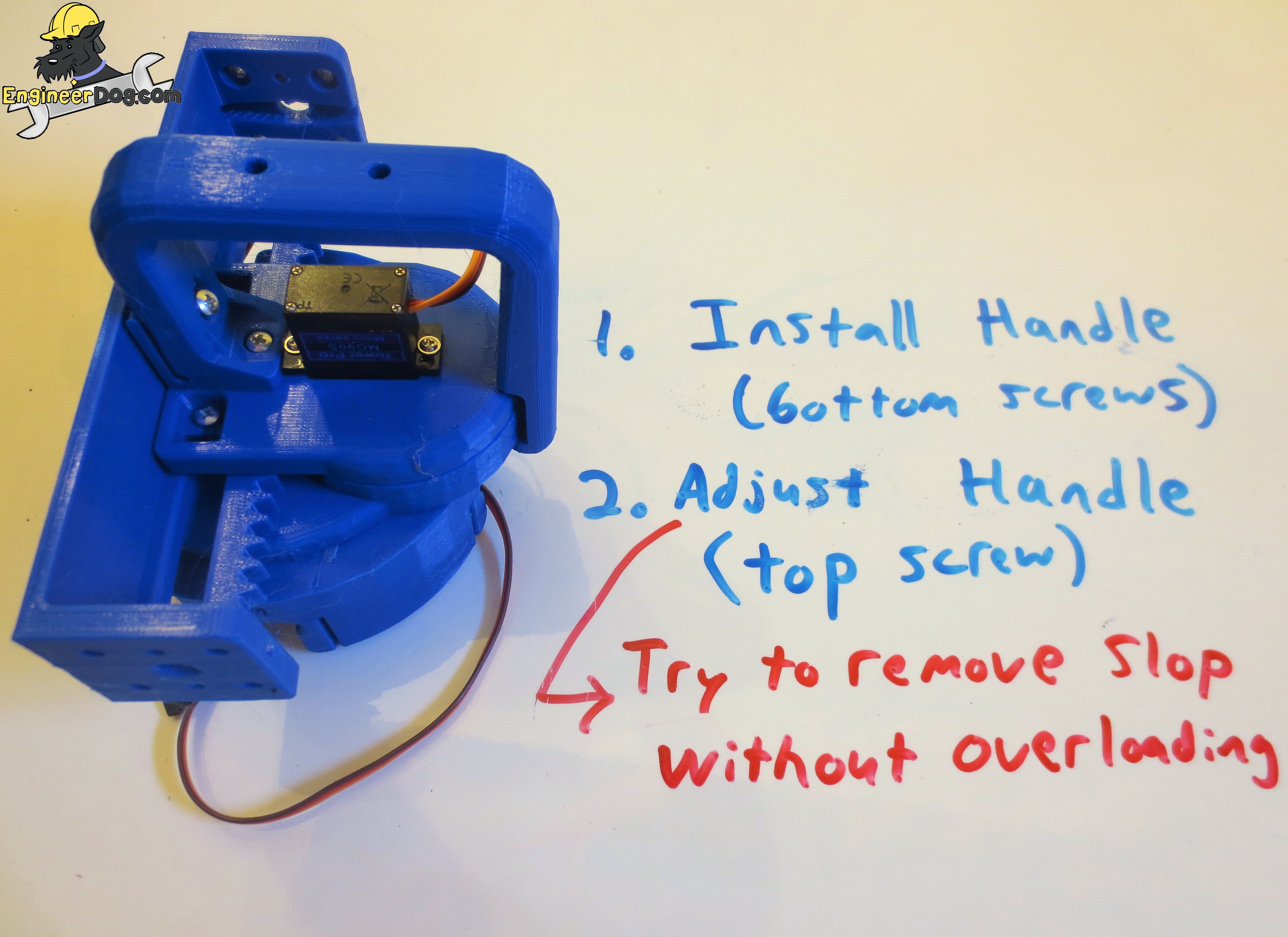
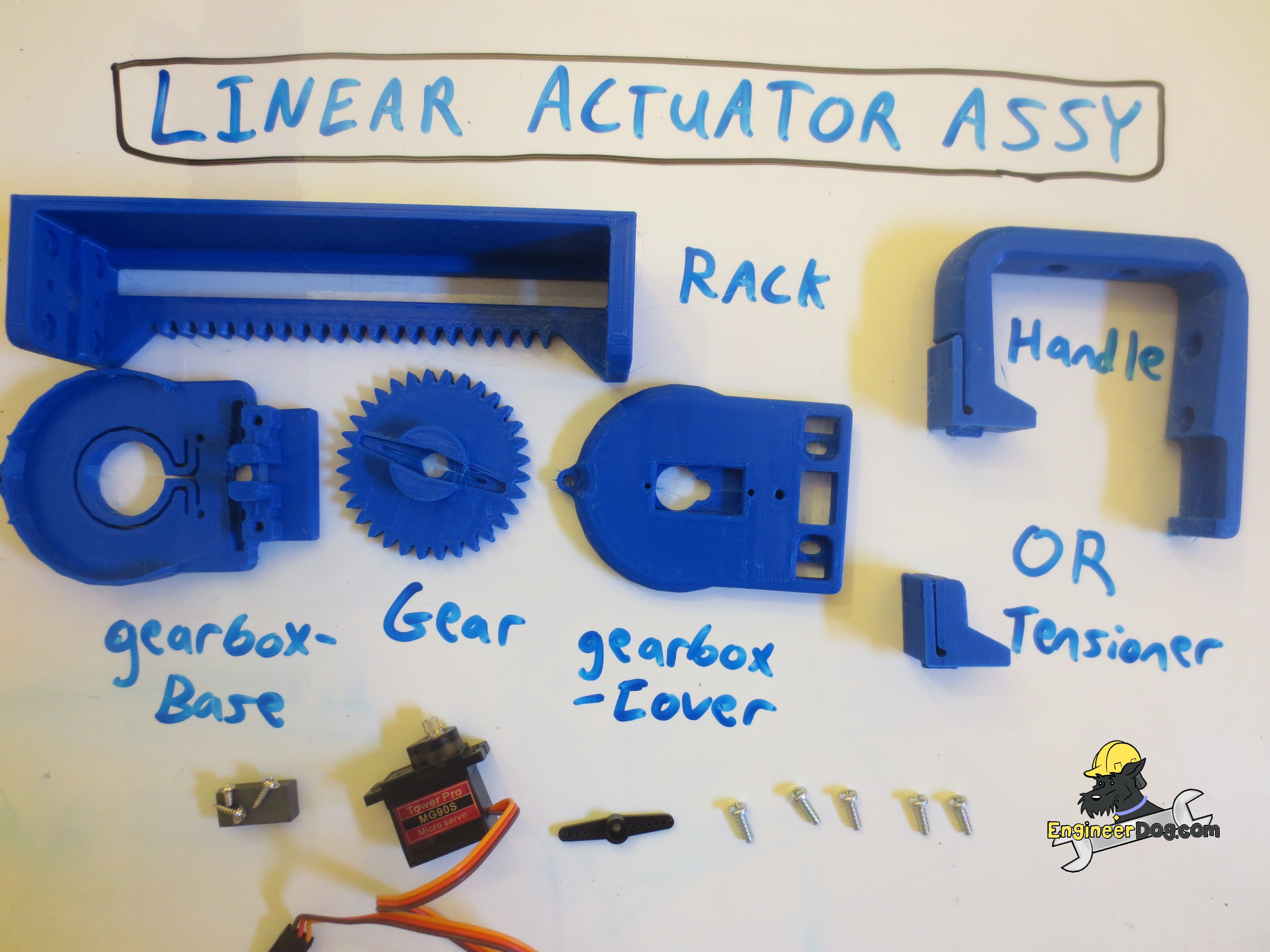
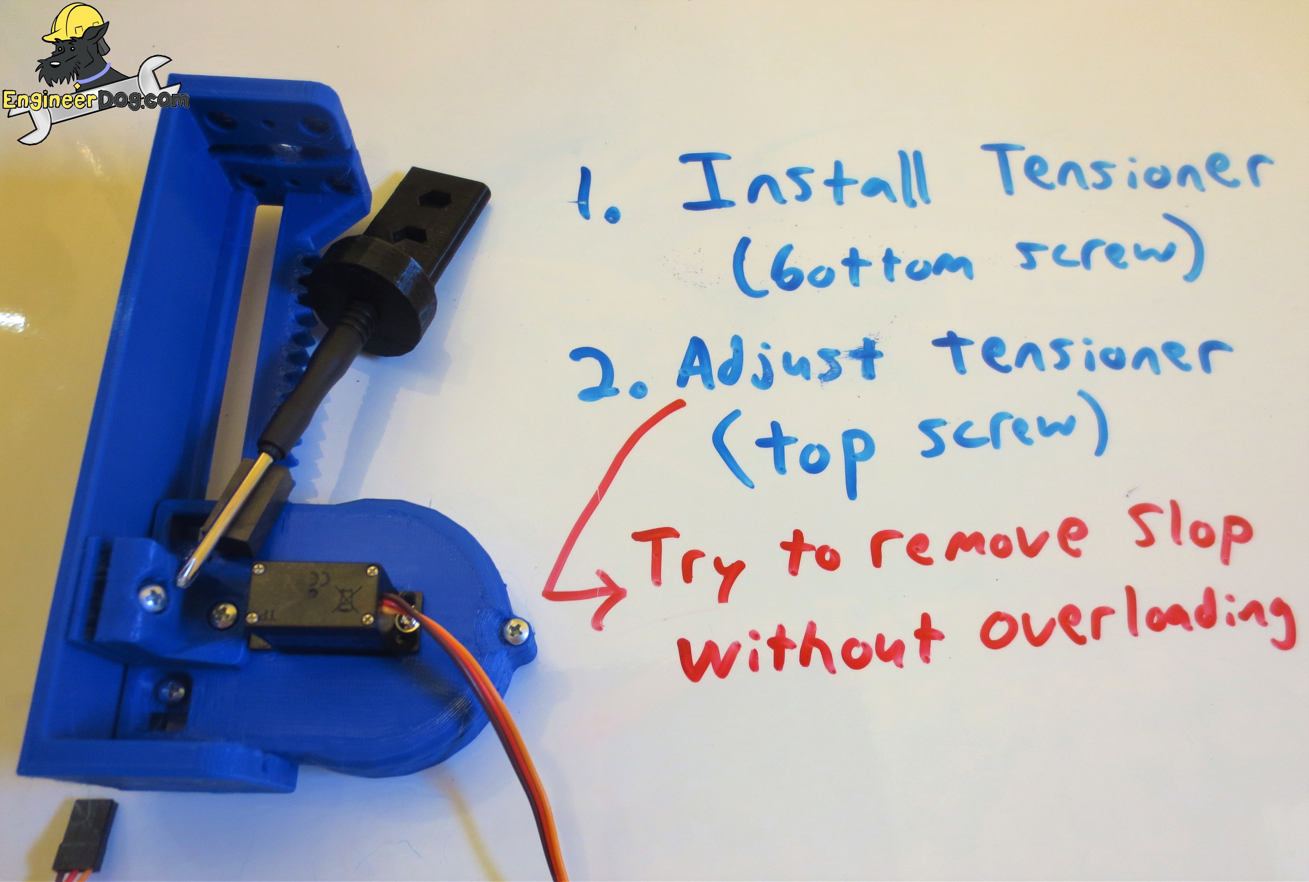
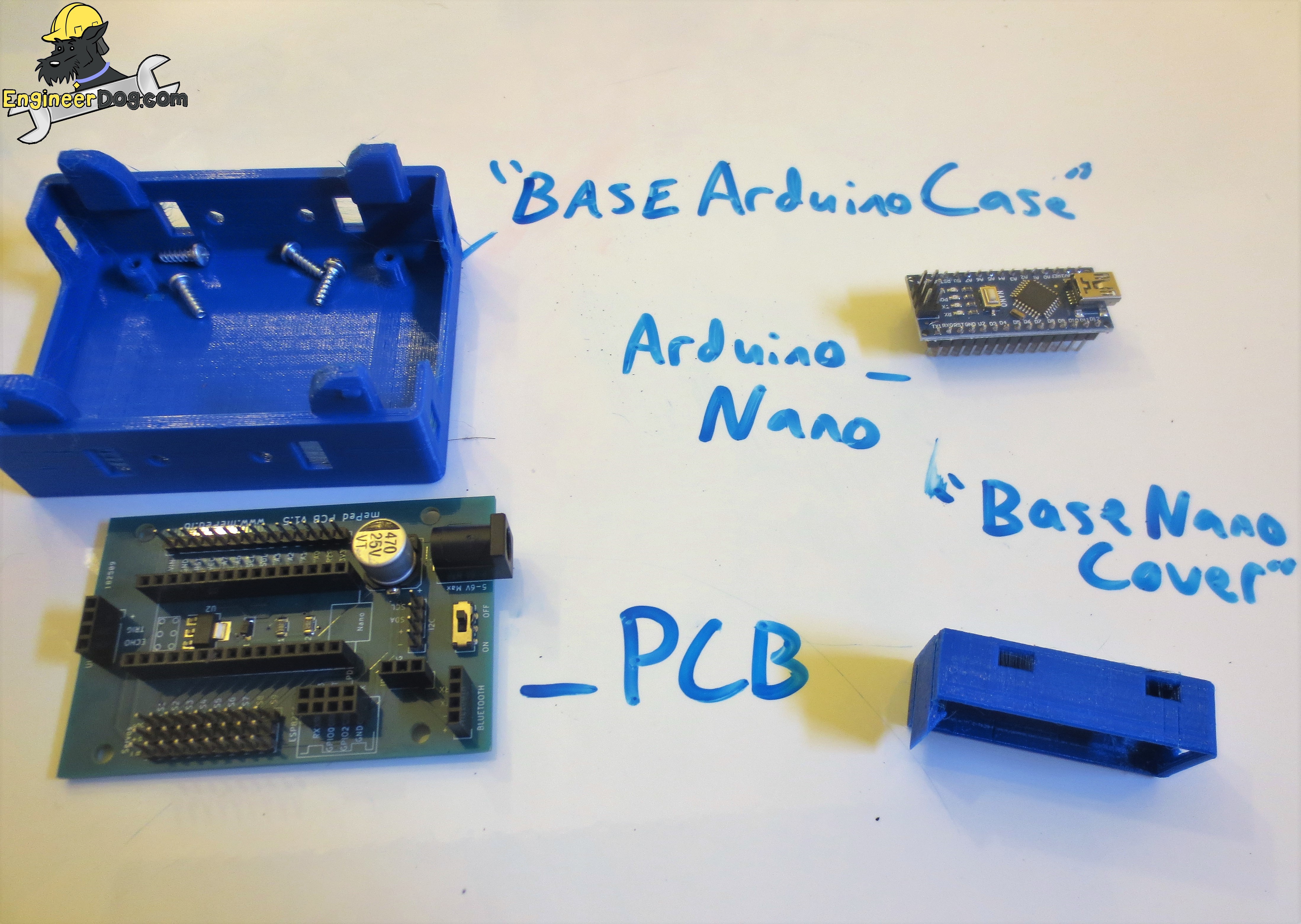
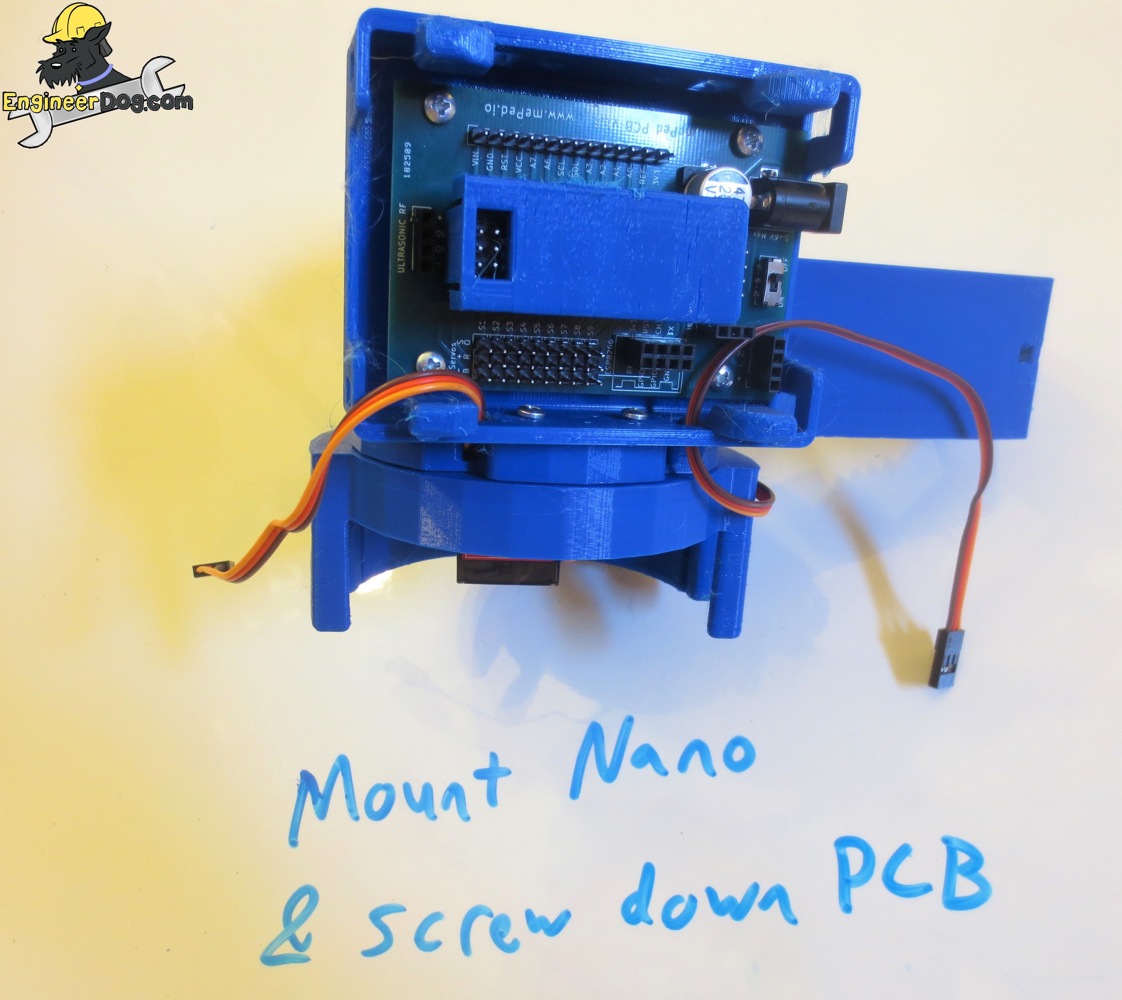
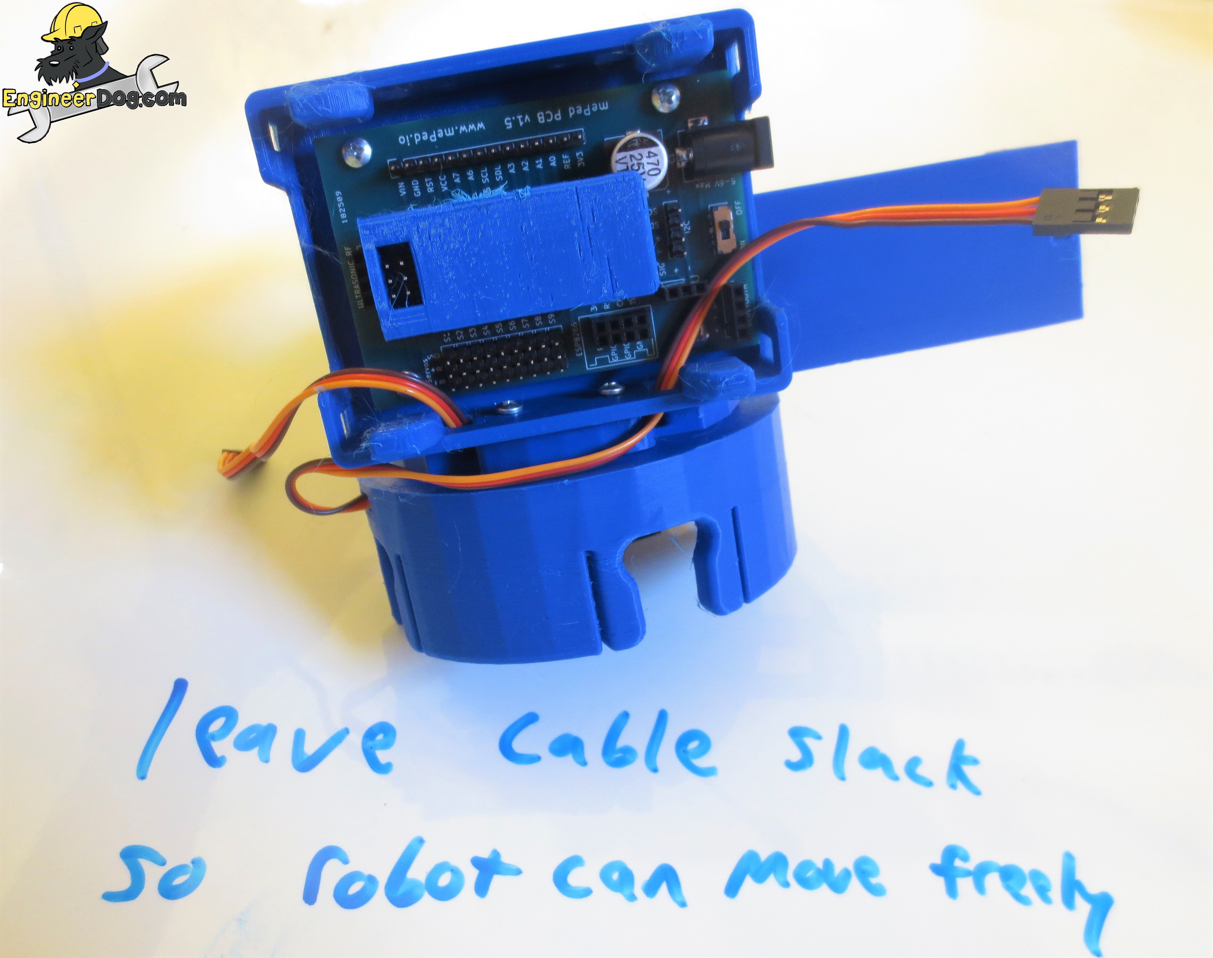
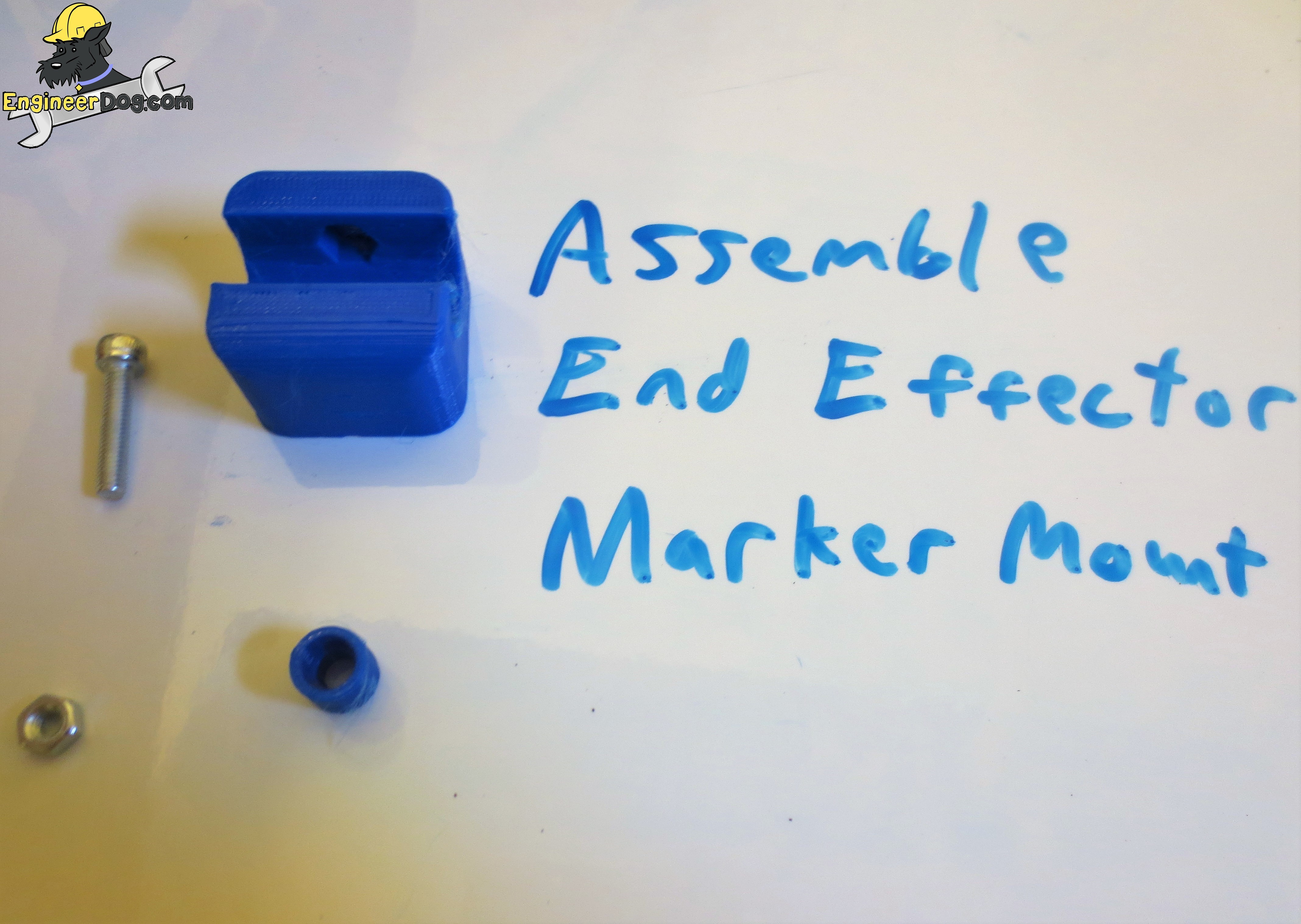
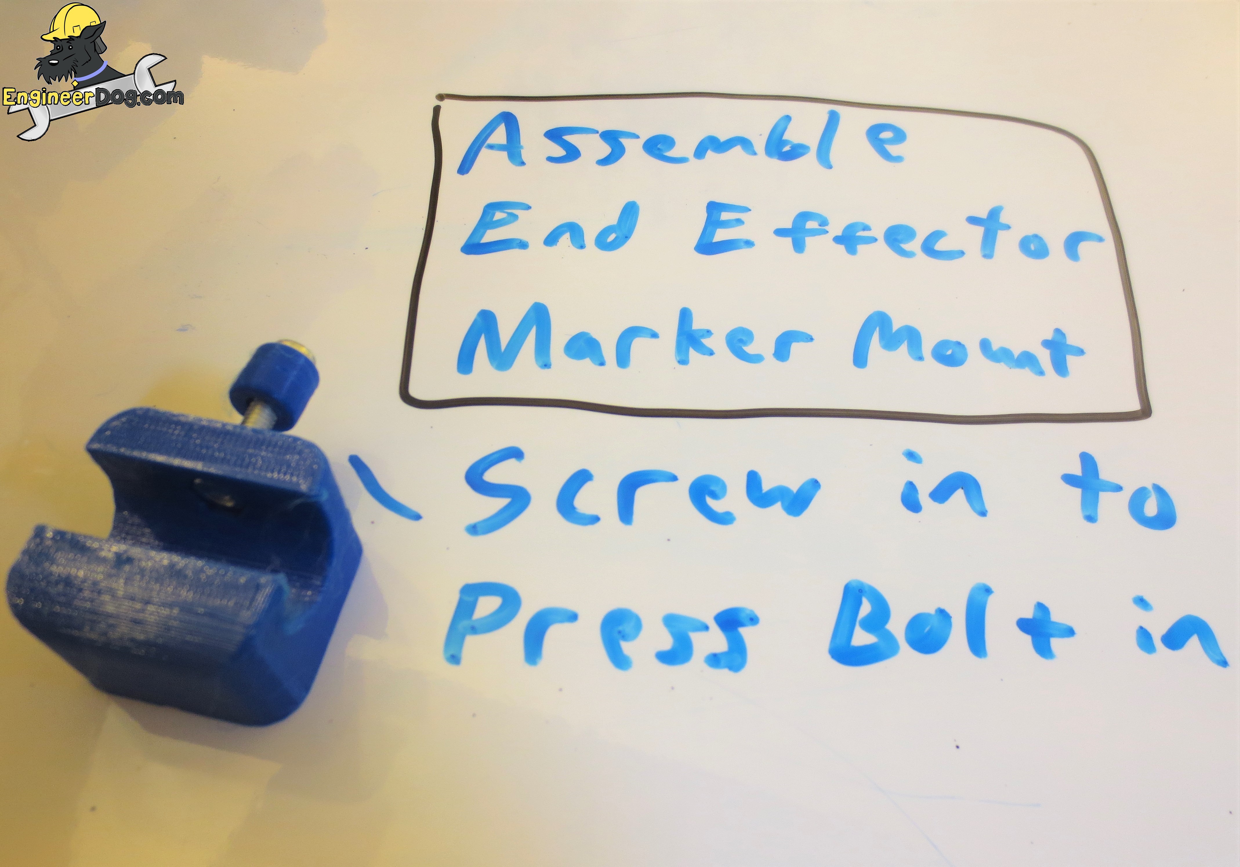
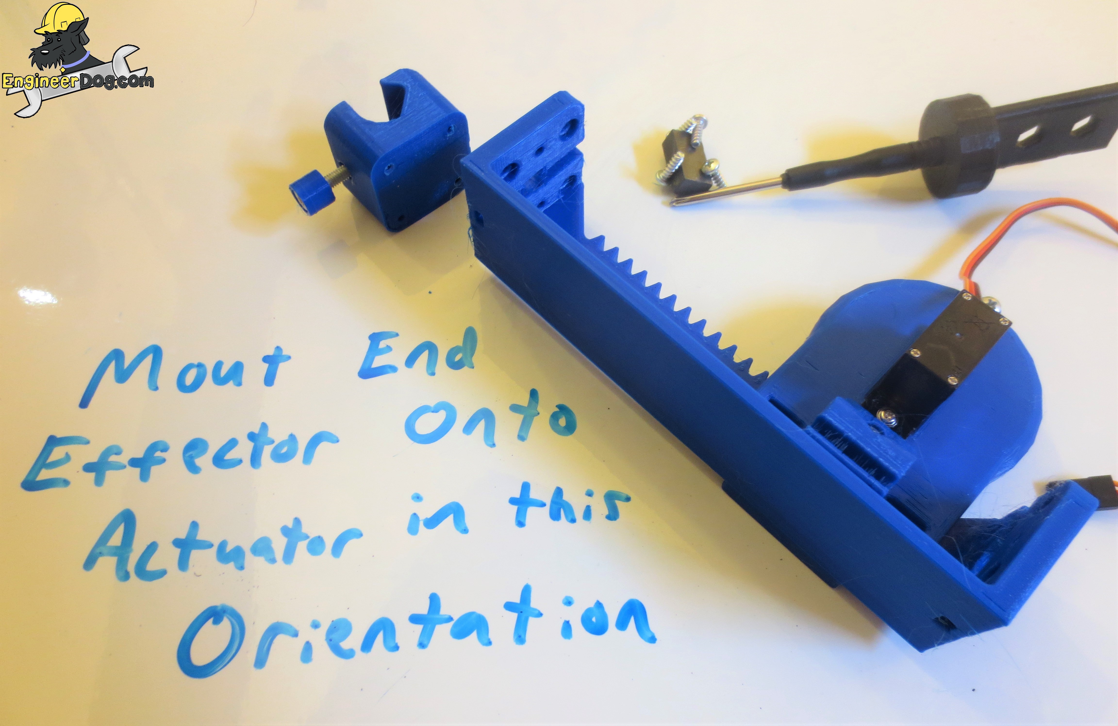
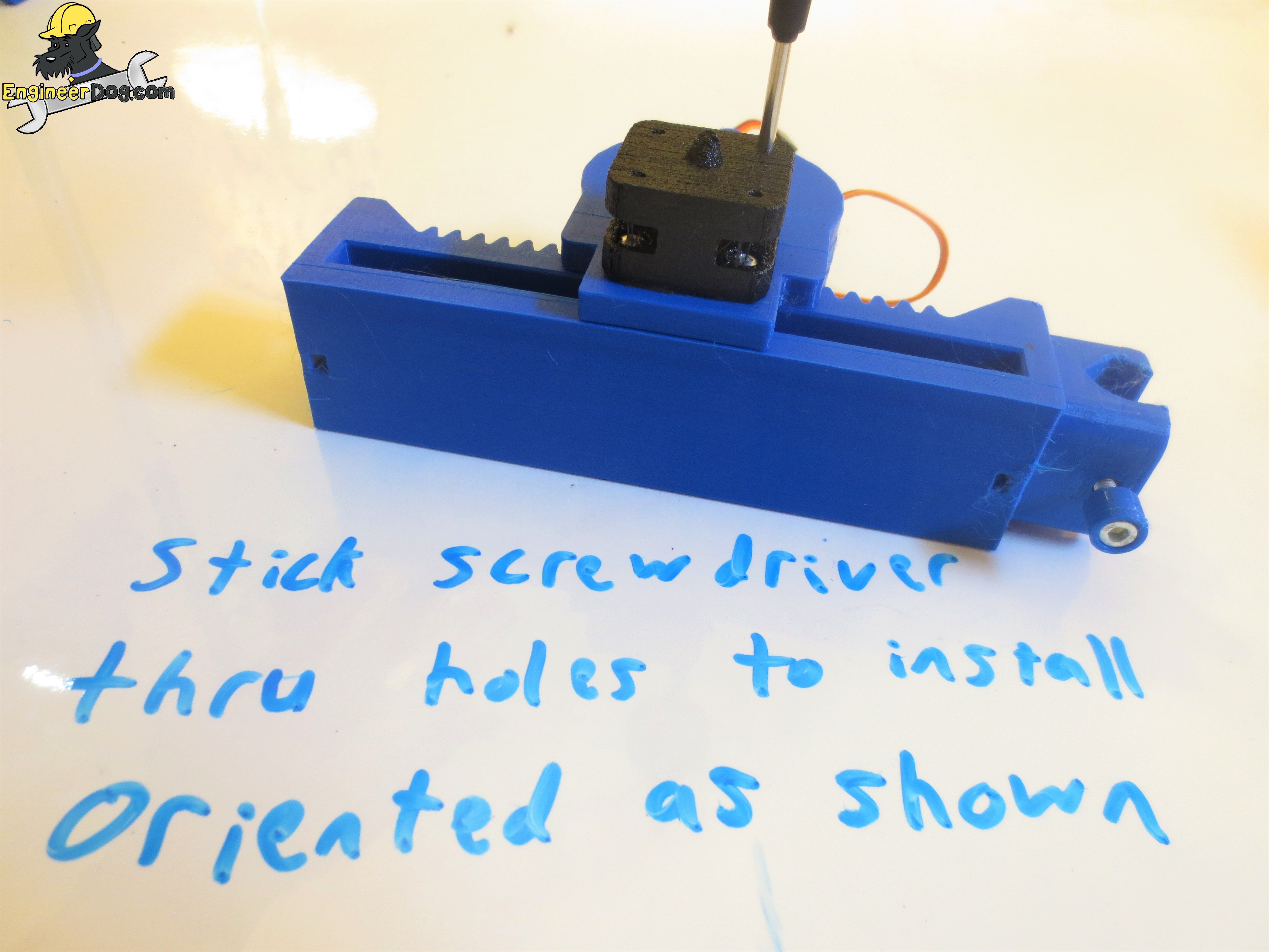
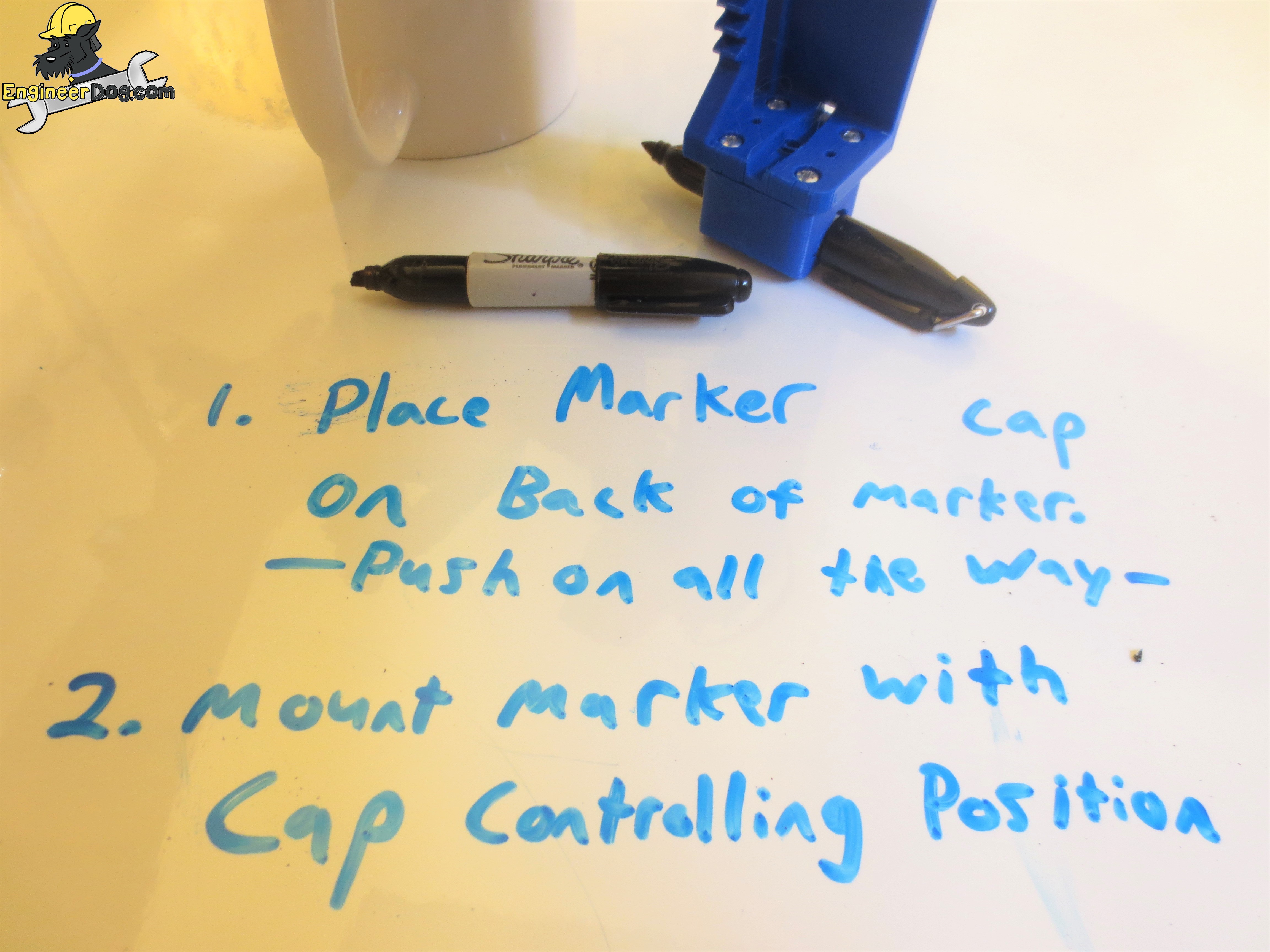
Also notice that these instructions are primarily in the form of images with a whiteboard background. I did this to facilitate sharing them!
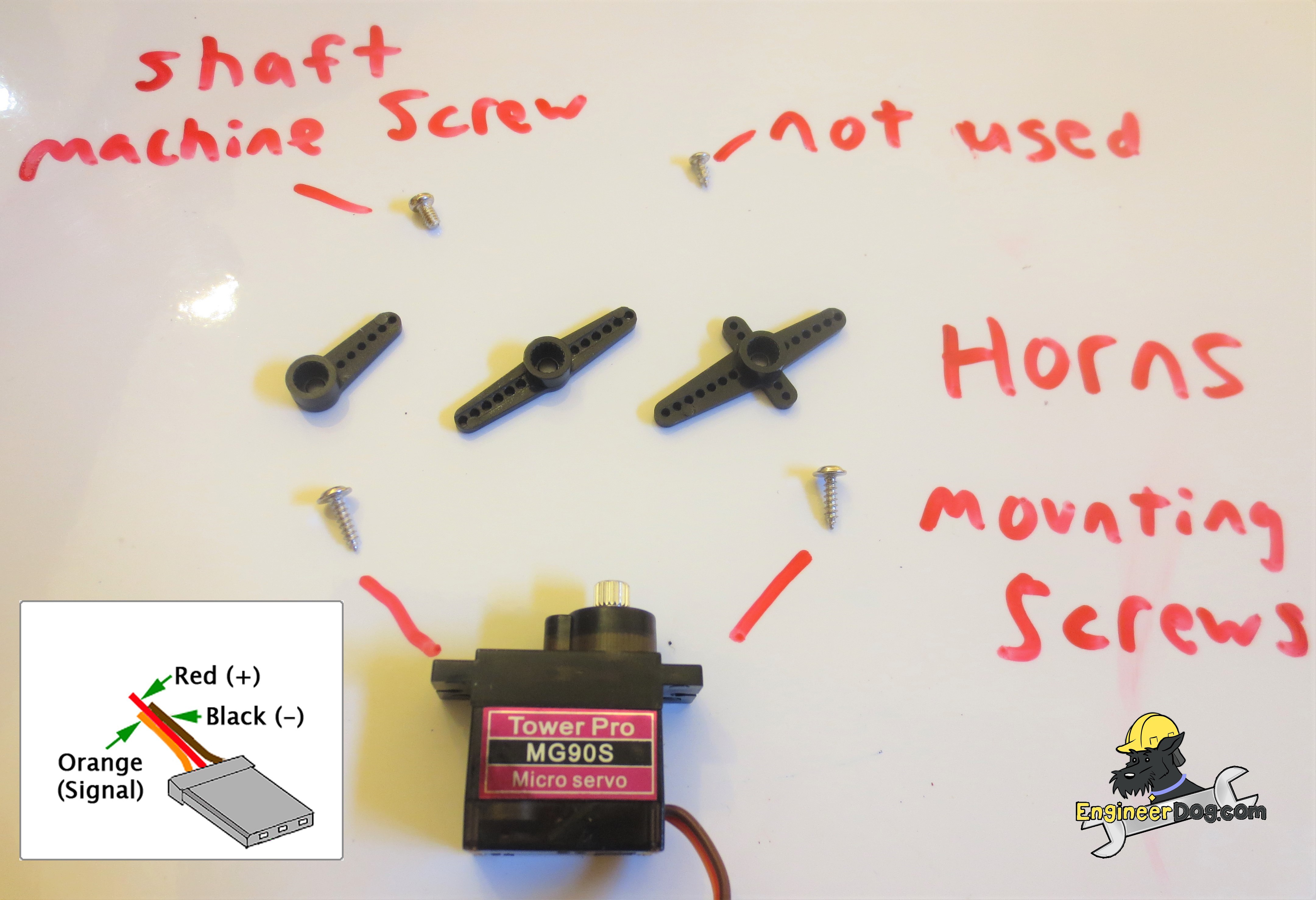
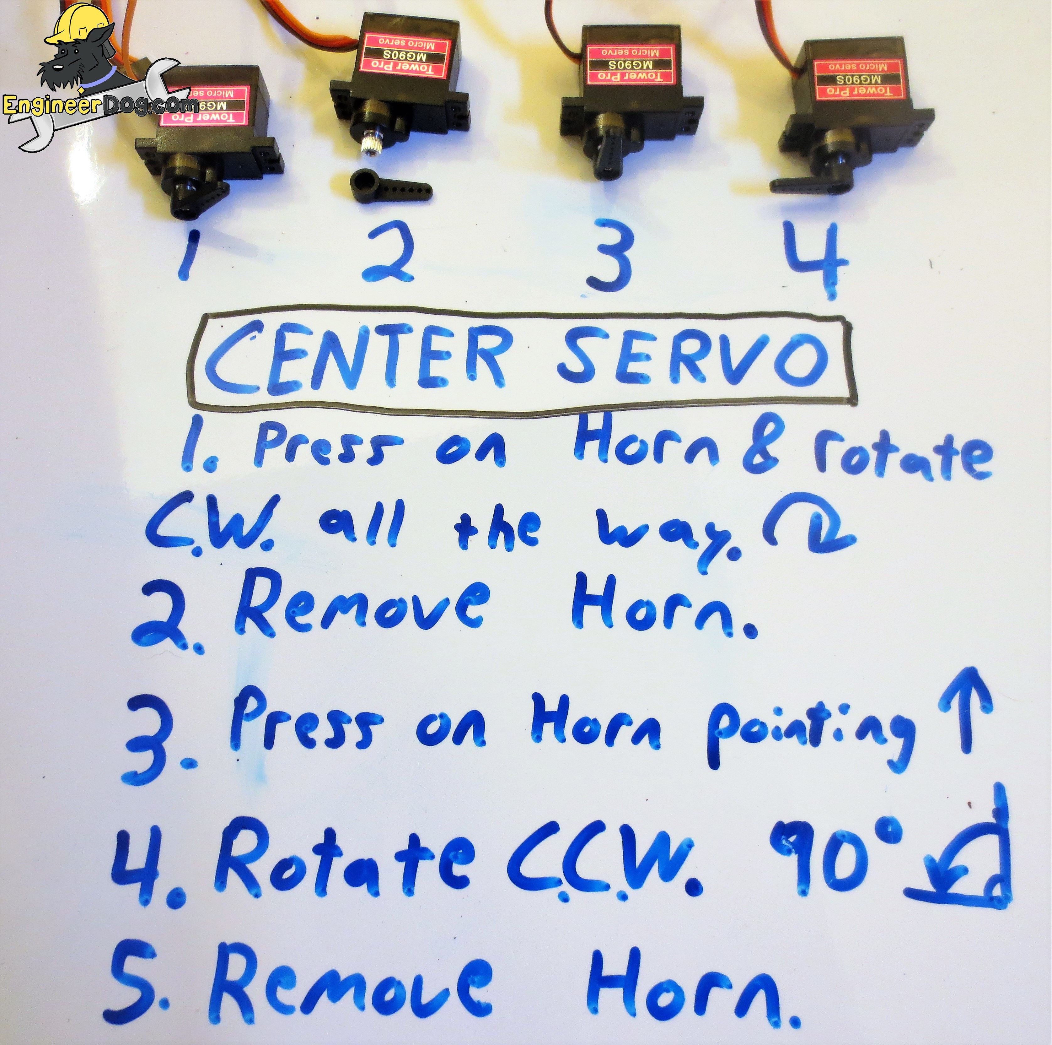
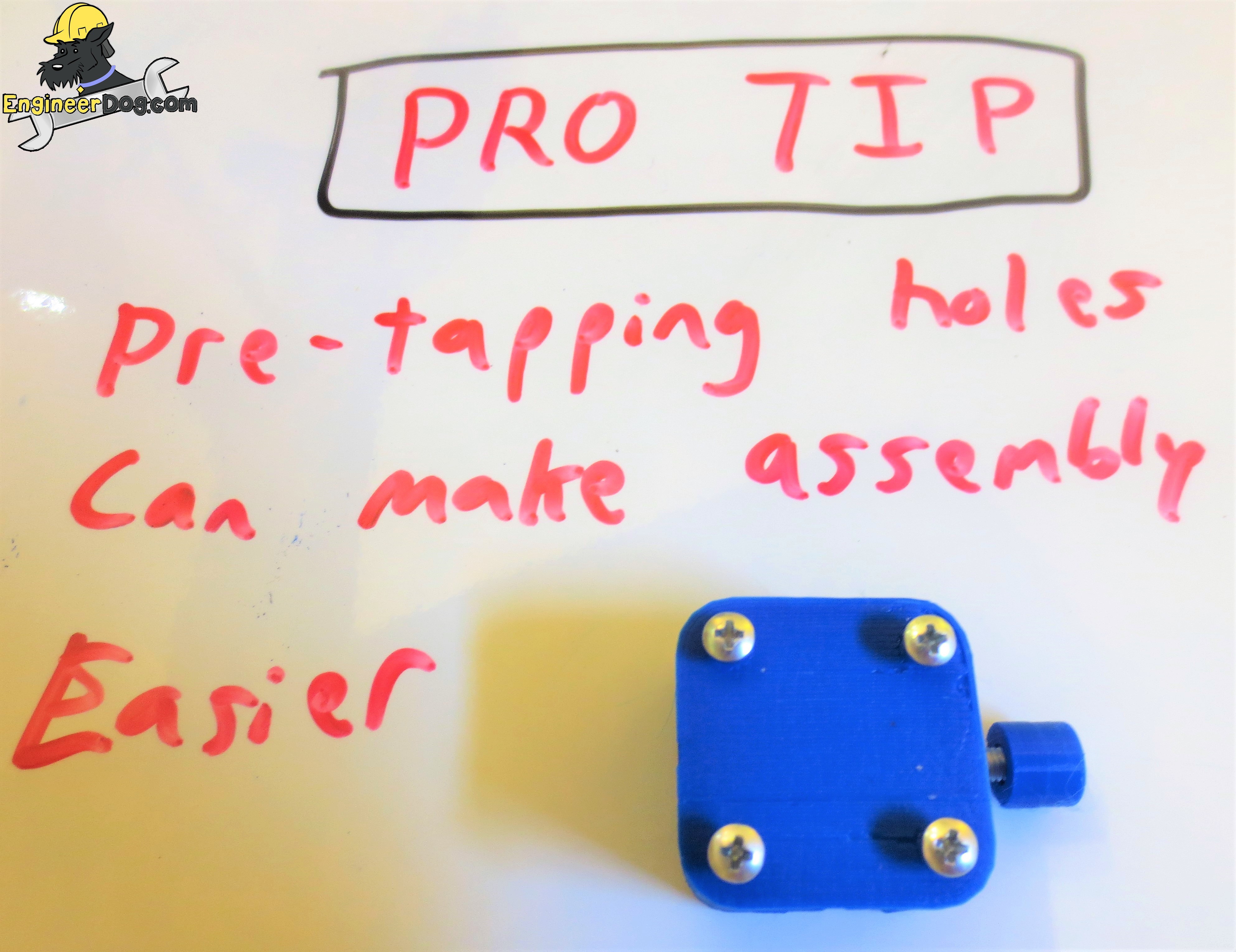
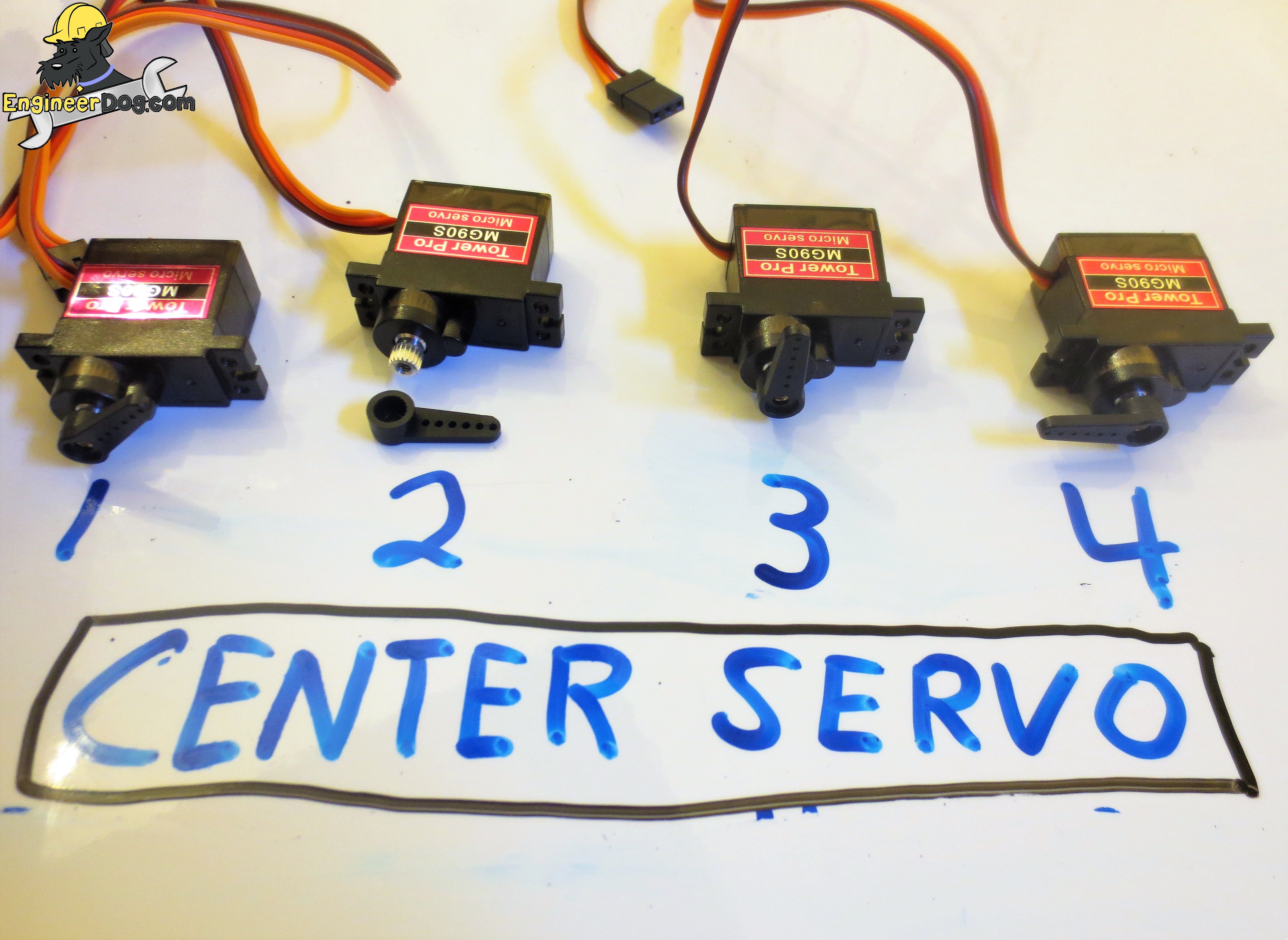
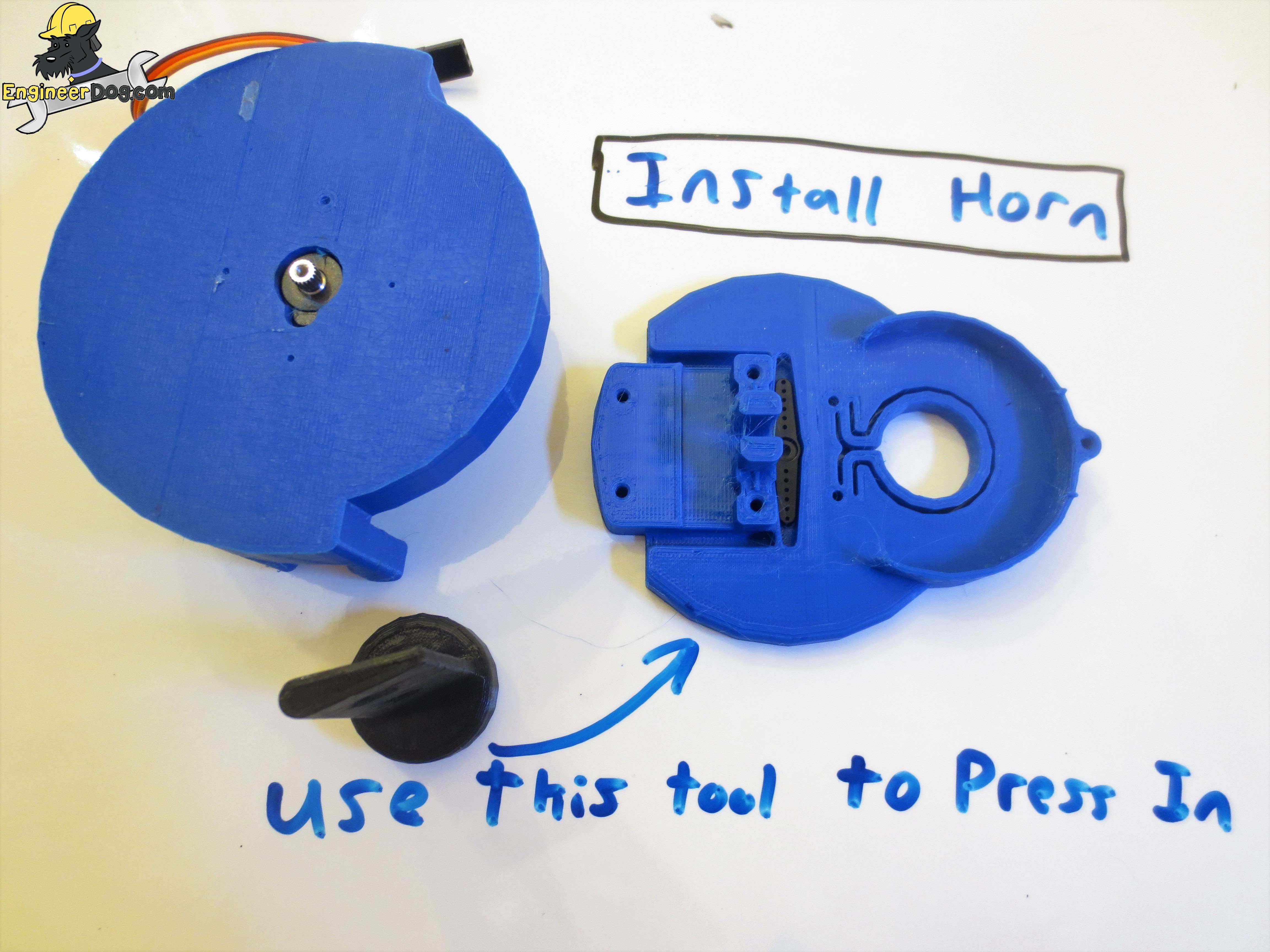
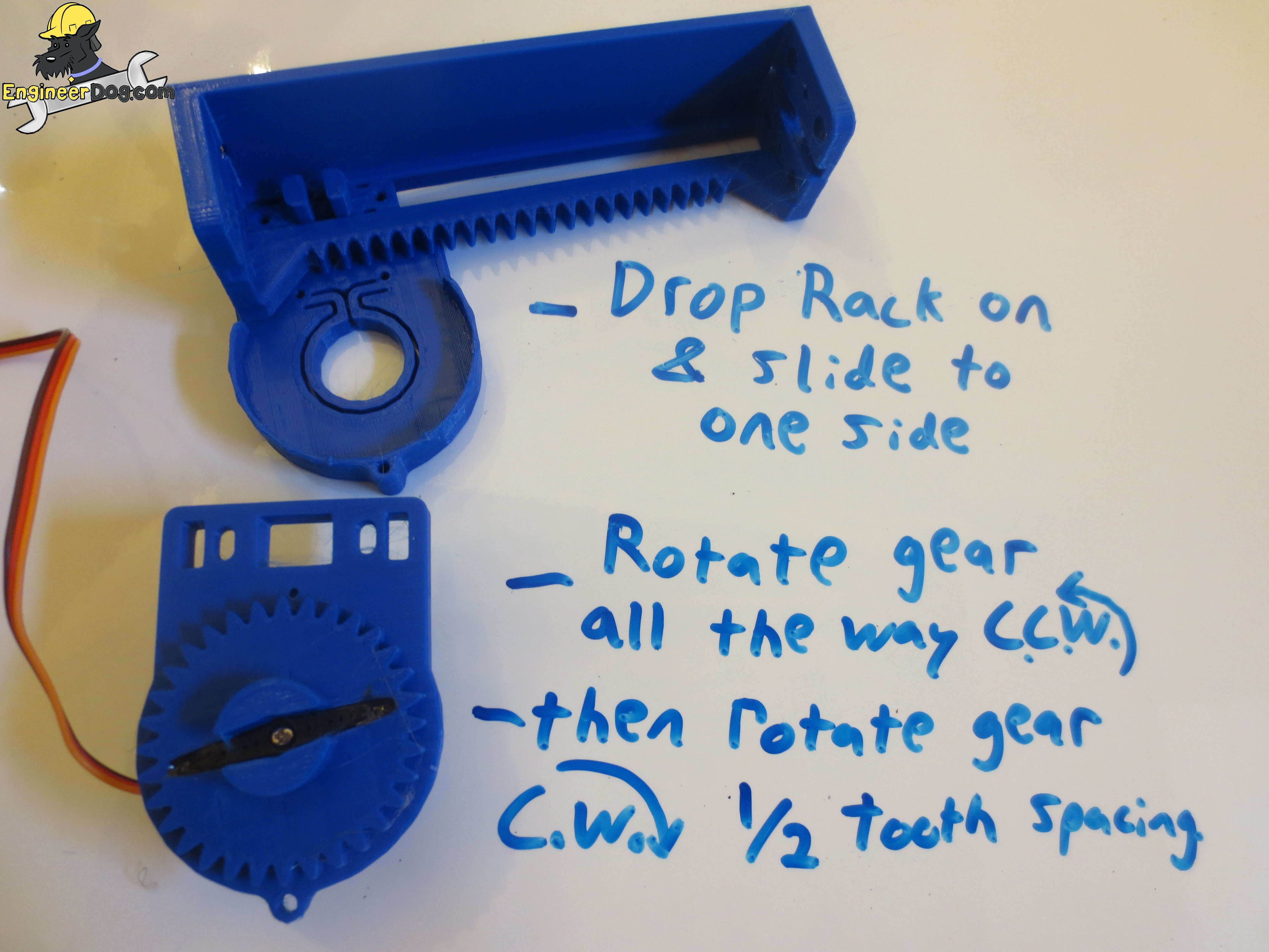
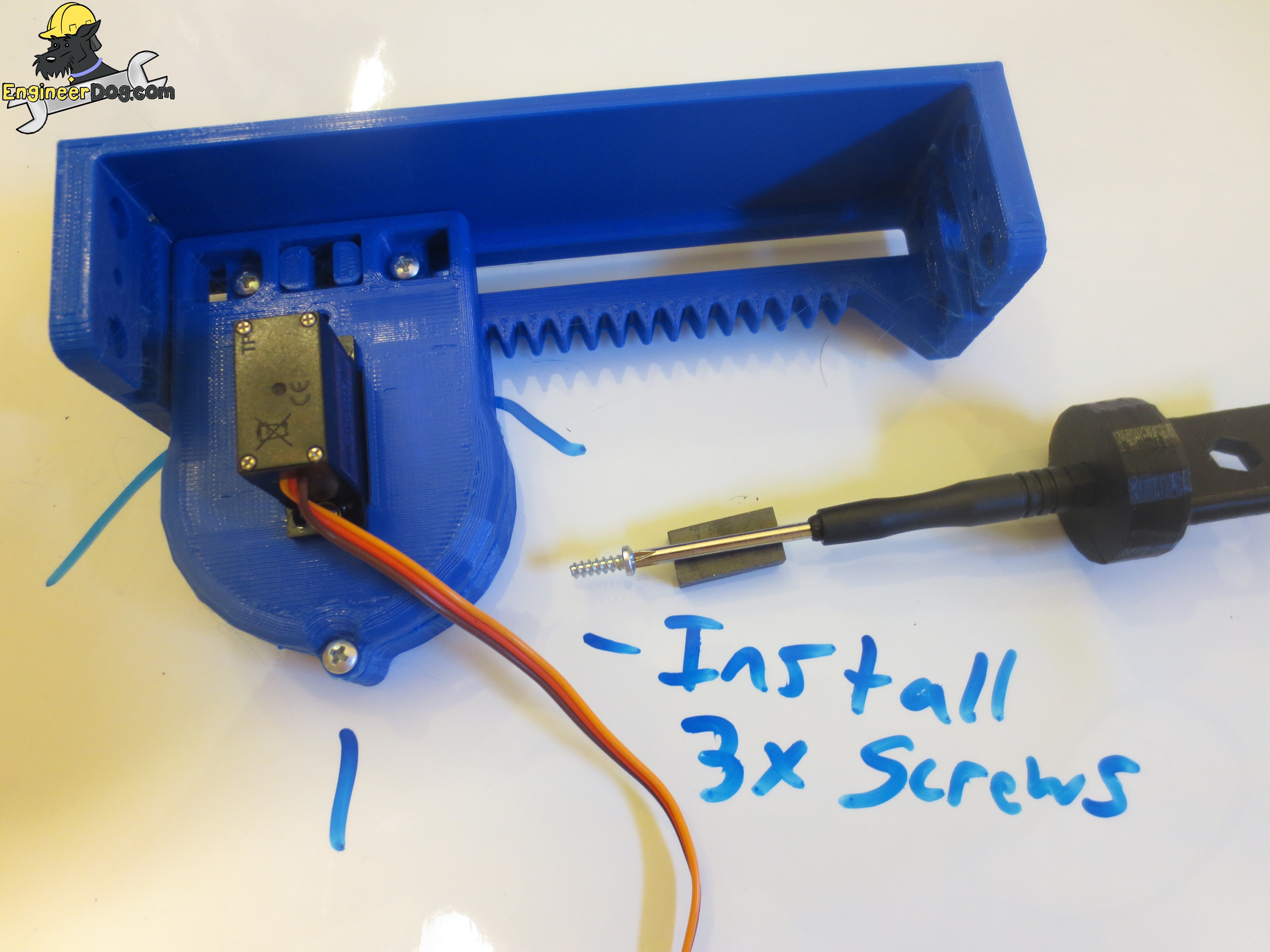
Note that the servos can be centered mechanically as shown below, or you can program the arduino so send them to 89.5 degrees for a more accurate centering. The TinyCNC collection is held together using Plastite screws which form their own threads as you drive them. For this reason it can be hard to drive them the first time you do so I recommend pre-screwing all your holes to form the thread before assembling parts together so you dont have to drive them from funny angles.
3
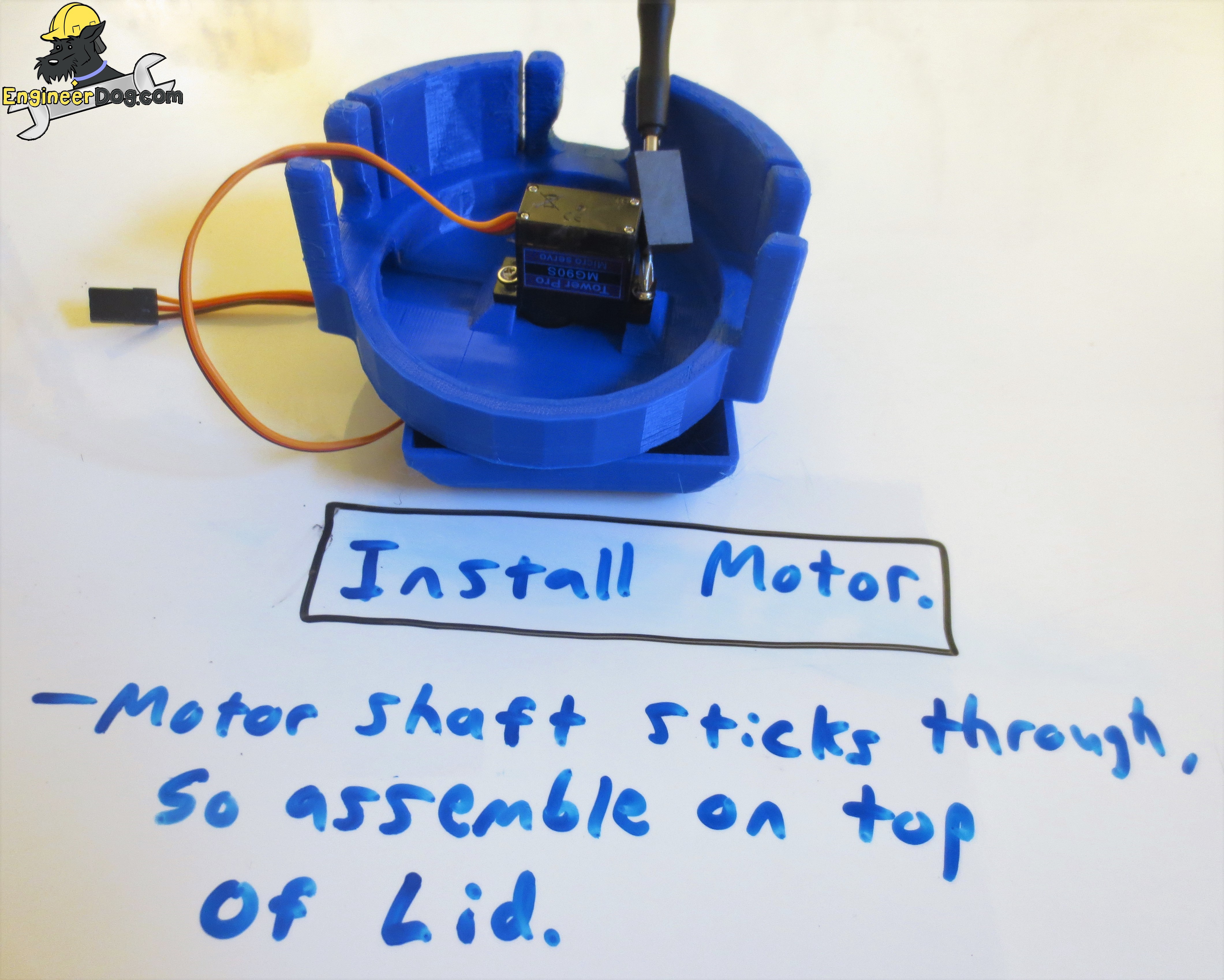
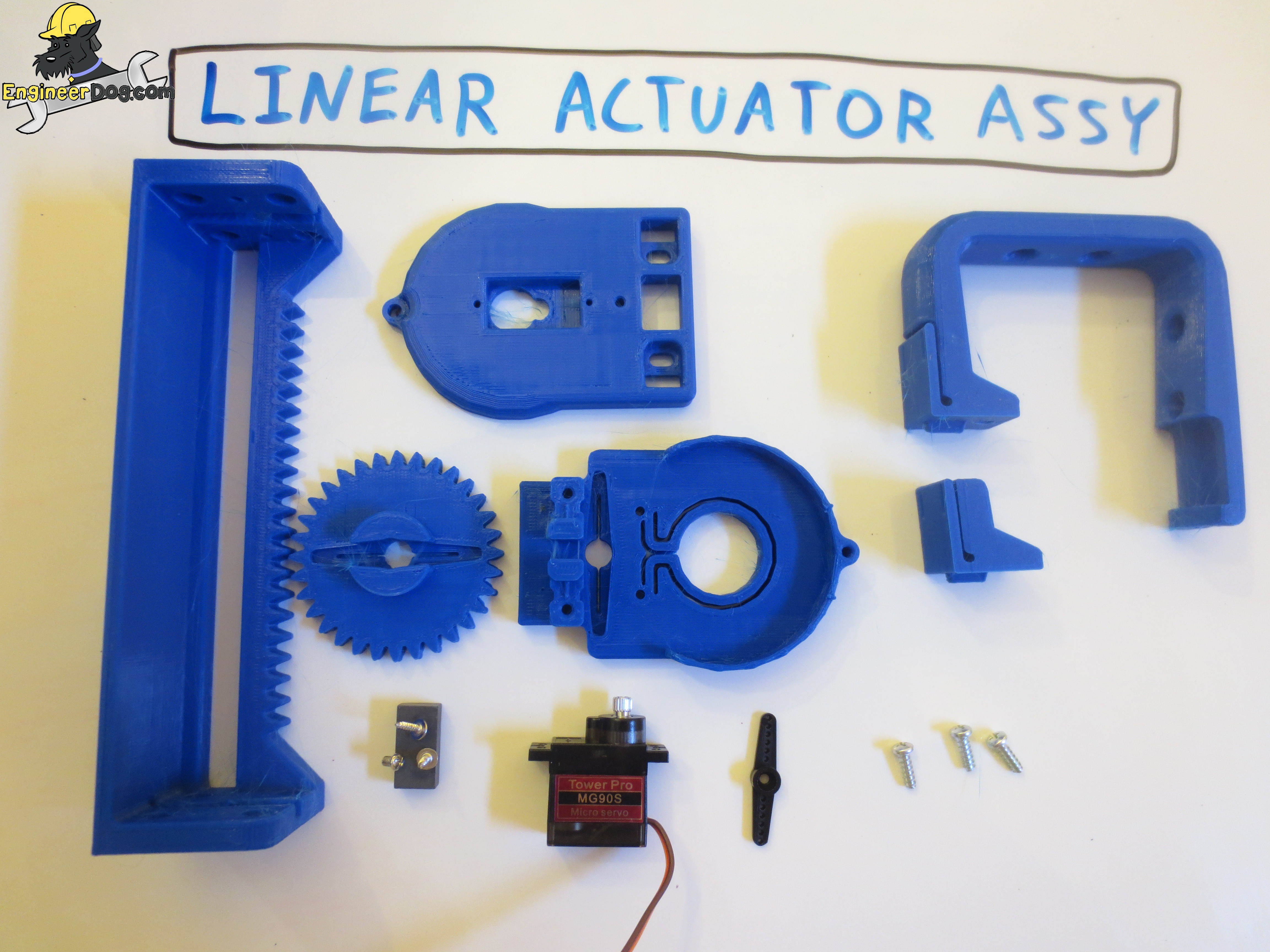
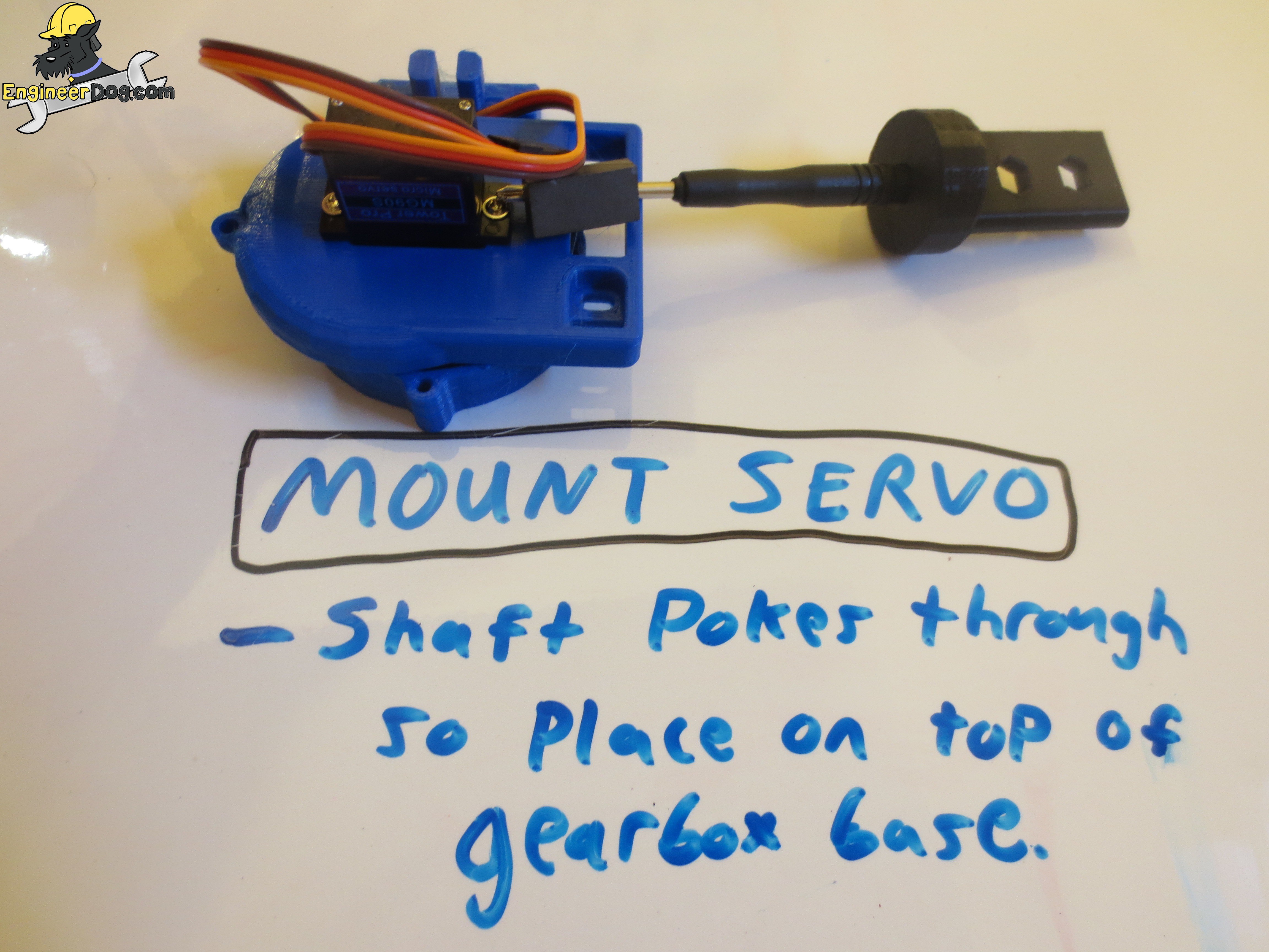
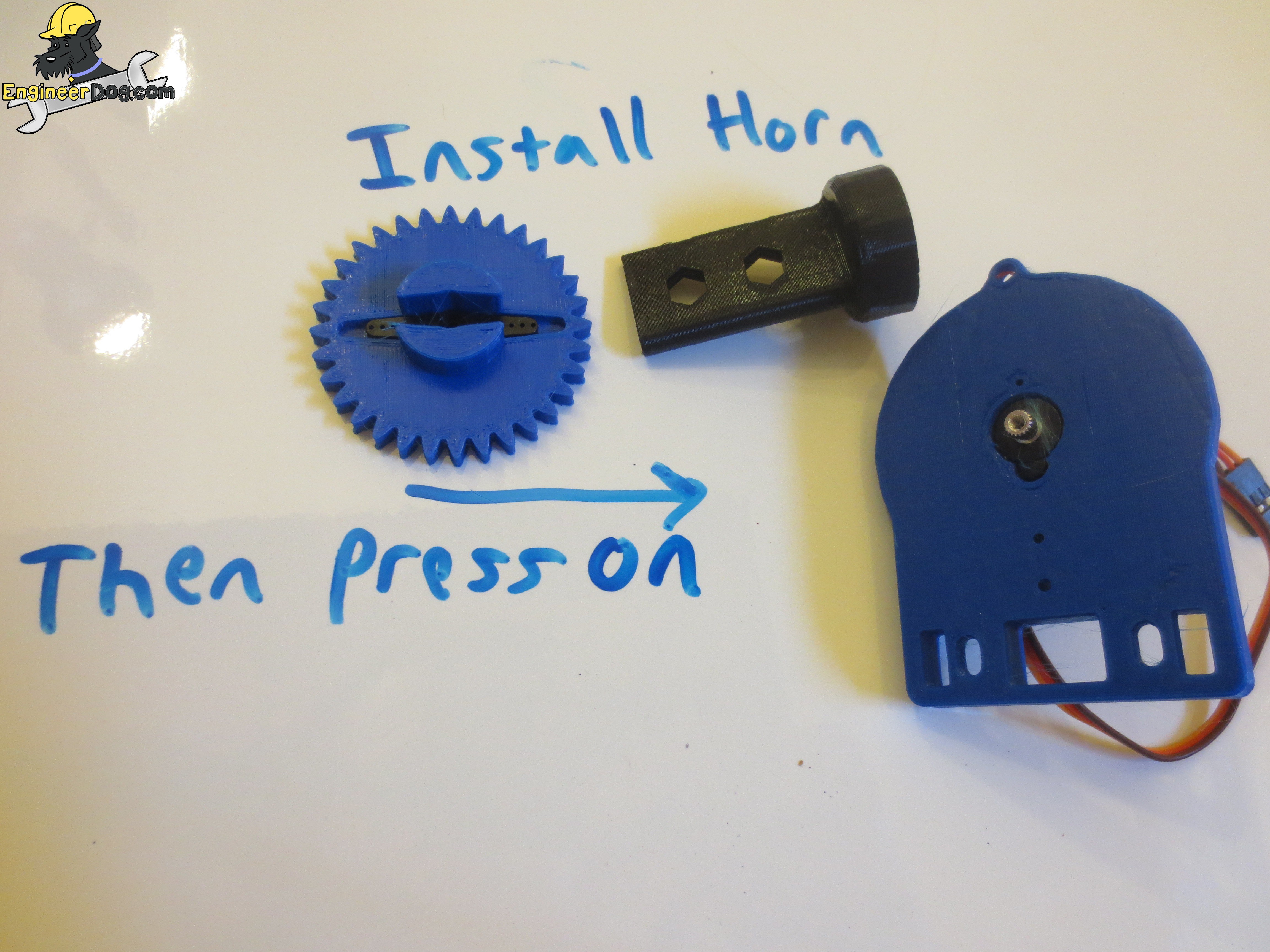
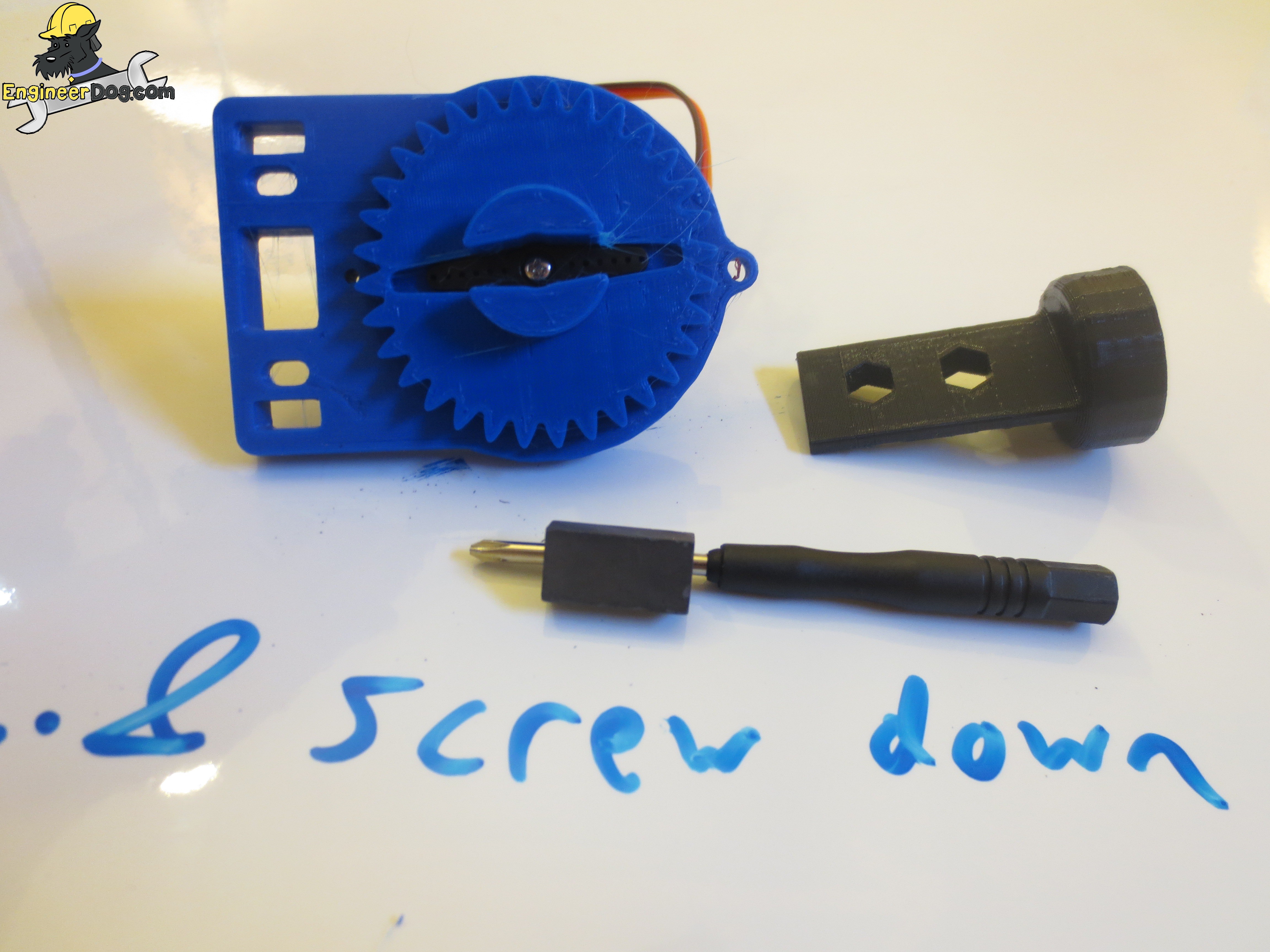
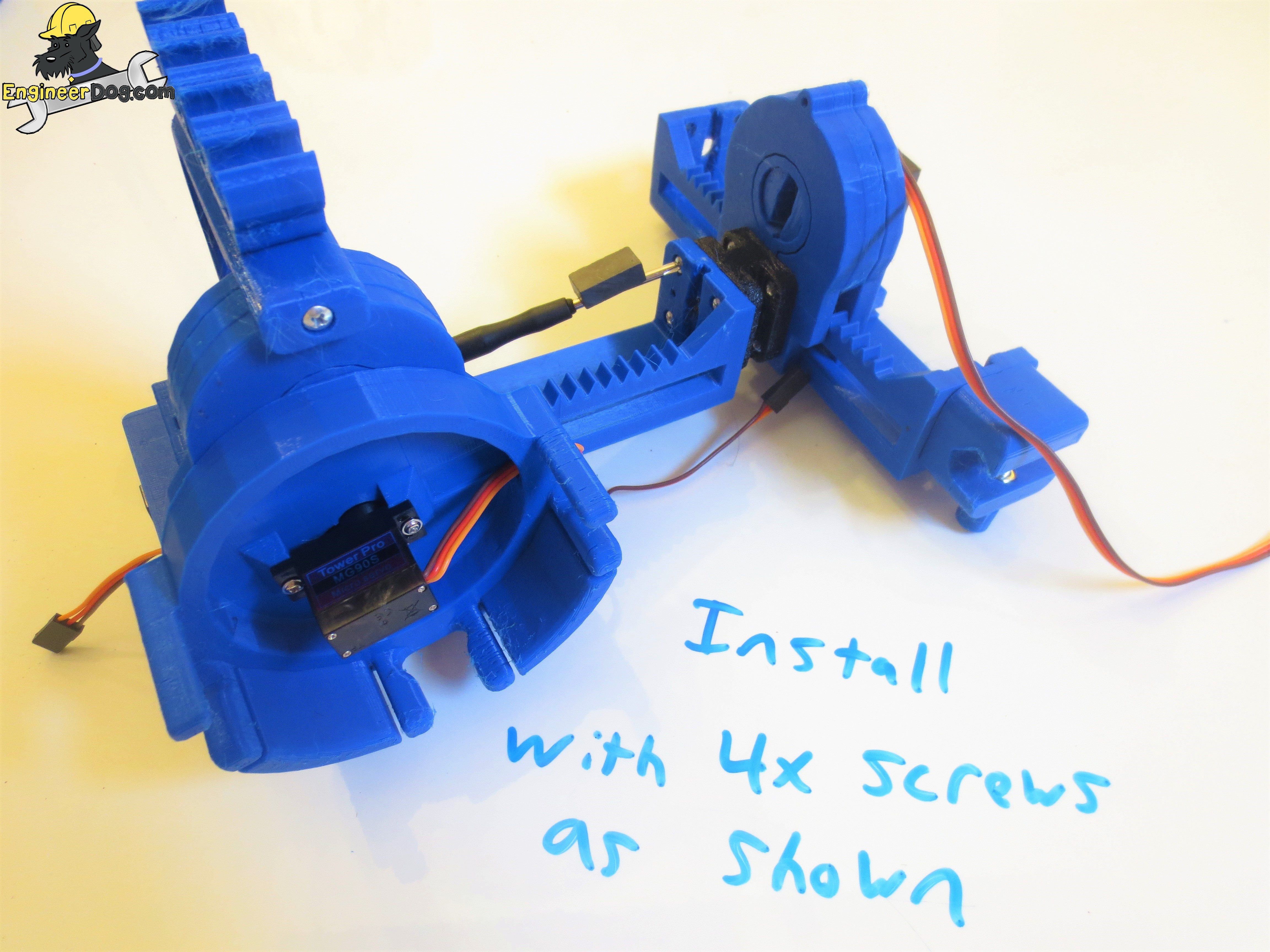
Build Mug Lid Assembly
IMPORTANT NOTE: At this stage I recommend taking a pea-size of grease and using a paper towel to apply it between the two surfaces that will move against each other. Wipe the grease into the crevices and then wipe off 90% of excess and basically just leave a shiny surface behind! It will feel wasteful but too much grease for these motors is like walking through deep mud! But that little bit leftover will be magic!
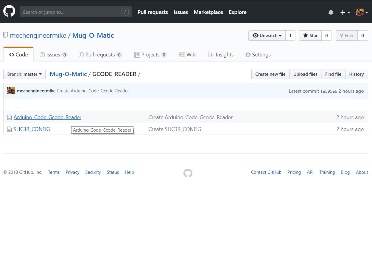
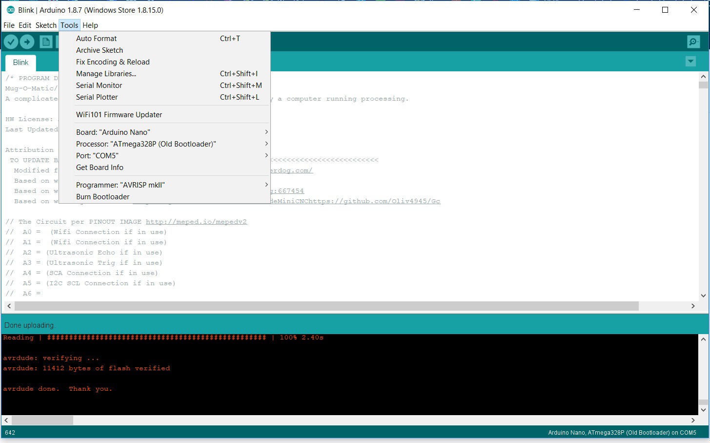
Download the latest Arduino IDE https://www.arduino.cc/en/Main/Software and paste the code from the TinyCNC Github in there. Connect the usb cable from your arduino nano to the computer & upload the code.
Notice the settings I selected on the arduino screenshot. My supplier for the arduino nano's provides them with the old bootloader type so you have to select that or it will error.
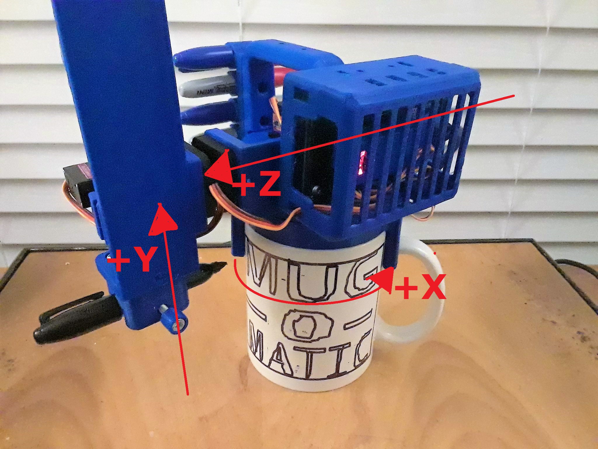
The standard gcode reading program has a bunch of built in functions. These are great for calibrating the machine to verify all your software settings match what they should in reality. If you follow my instructions all of your motors should be within a couple degrees of where mine are and you can adjust the positions from there.
To get your machine calibrated just stick with my default motor positions for now and well do a guess and check procedure.
In the *SETUP* section there are a bunch of commented out commands. You can un-comment to do calibration checks before a gcode job. First I suggest checking your servo Z to make sure your marker touches the mug exactly at the ZdTouch position.
Then try to send your robot home (@Xmin, Ymax, Zmax) and make sure the en is not crashing into the frame. Then try to draw a rectangle spiral to check if the max & minimum X & Y positions are happy.
Then try to draw a regular 20mm square and verify with a ruler that it is the right size and the first and last ends line up.
//drawRectSpiral(Xmin,Ymin,Xmax,Ymax,6, true); //(x0, y0, x1, y1, spiral spacing, boolean pen toggle (dry run if set false)). Units are millimeters
//drawRect(Xmin+30,Ymin+26,Xmin+56,Ymin+52,true); //(x0, y0, x1, y1, boolean pen toggle (dry run if set false)). Units are millimeters //delay(9999999999); //turn motors off forever
...
In the *DEFINE DRAWING SETTINGS* section
// Define Robot limits, in degrees float Xdmin = 12.5; float Xdmax = Xdmin +139.5; float Ydmin = 0; float Ydmax = 180.0; float ZdTouch = 13.0;// The exact angle that you begin to touch pen to mug float Zdmin = ZdTouch -1; //the low position it will bounce to when drawing dots float Zdup = ZdTouch +10; //The high position it will bounce to when drawing dots float Zdmax = 46.0; //Fully Lifted Pen Position
10
Drawing- Preparing Your Image
Summary of Steps:
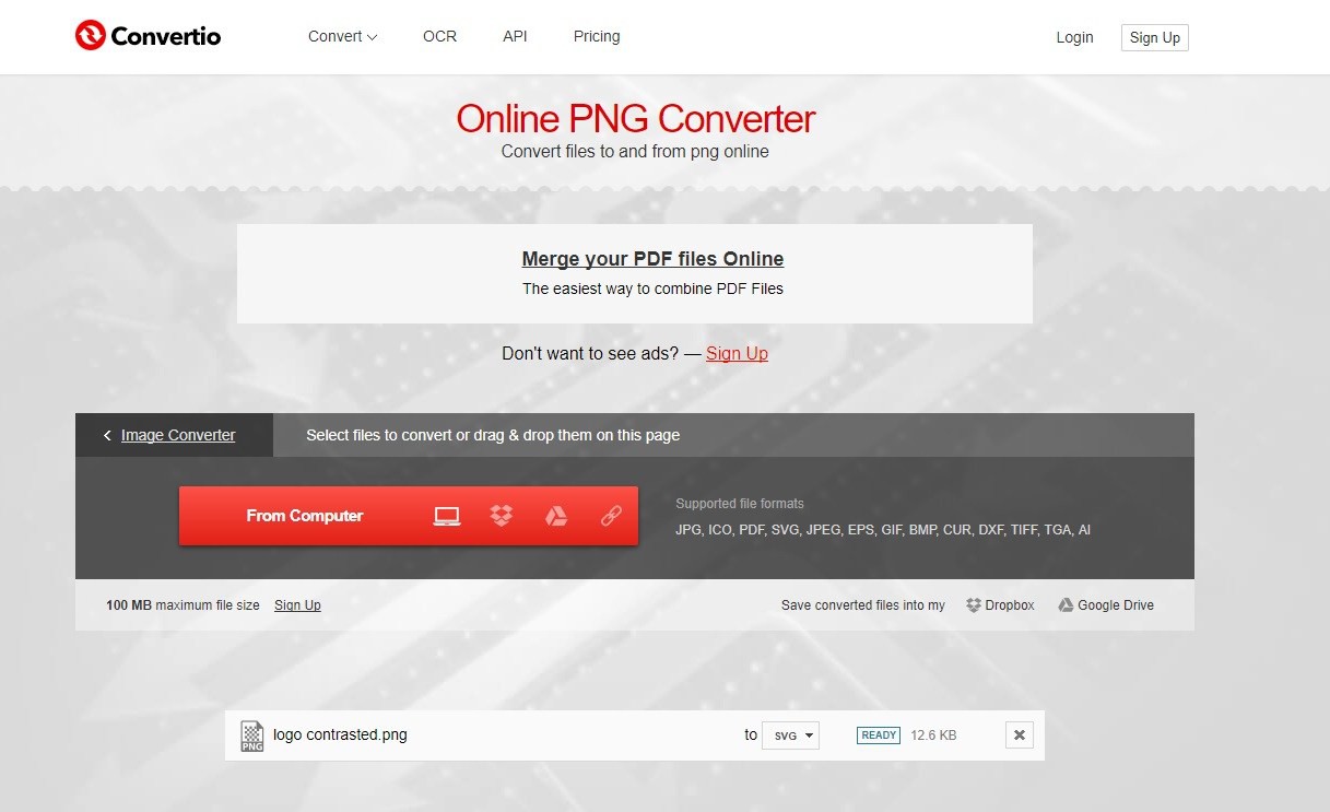
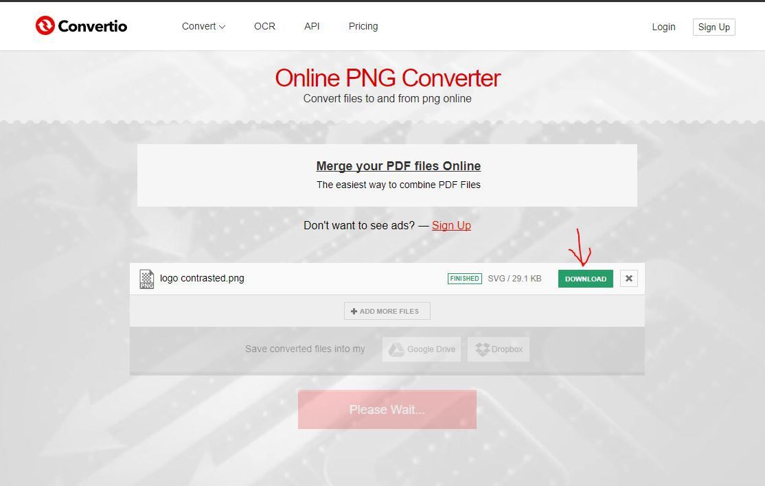
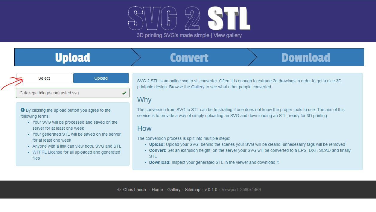
1. Create or find desired Image. A PNG type is ideal but most any will do. For finding great immediately ready to use images google search "black & white emoji" or "black & white clip art".
2. Convert Image to black & white high contrast outline. (white to become empty space, black to be printed) Use Pixlr.com or Microsoft Office tools, or just find an image that is already like this.
 Michael Graham
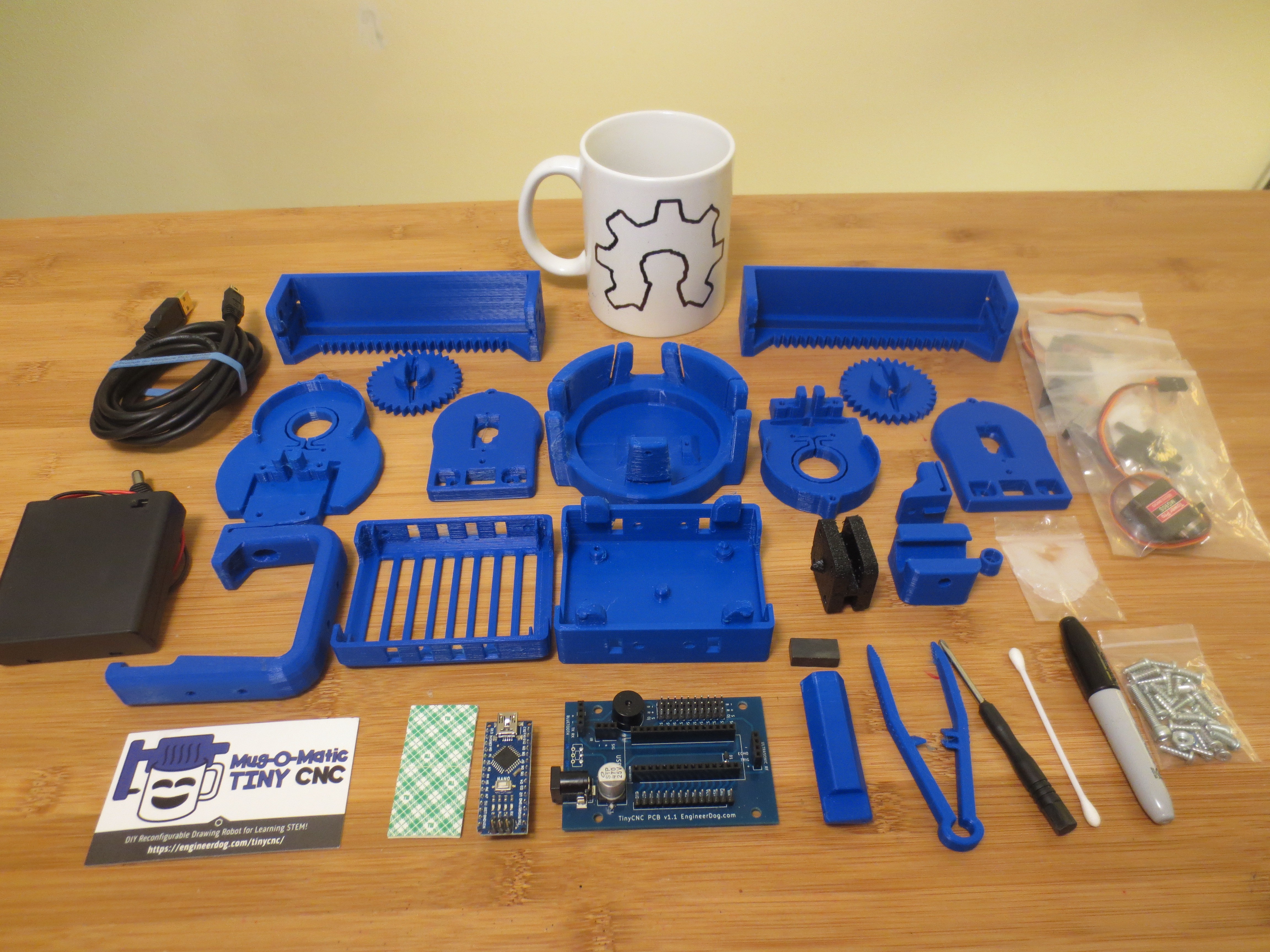
 IMPORTANT NOTE: At this stage I recommend taking a pea-size of grease and using a paper towel to apply it between the two surfaces that will move against each other. Wipe the grease into the crevices and then wipe off 90% of excess and basically just leave a shiny surface behind! It will feel wasteful but too much grease for these motors is like walking through deep mud! But that little bit leftover will be magic!
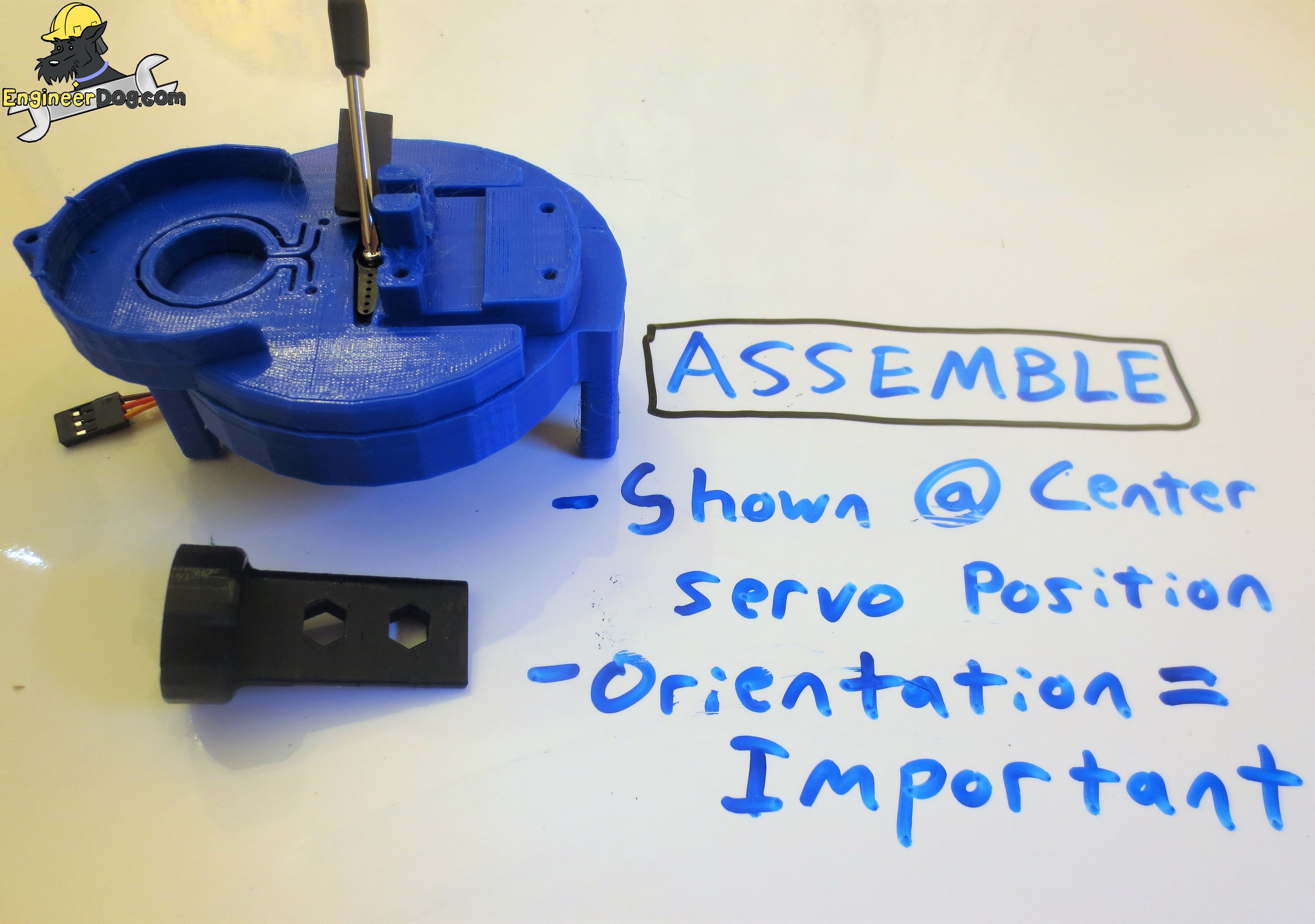


Discussions
Become a Hackaday.io Member
Create an account to leave a comment. Already have an account? Log In.