-
Official HackADayPrize Video Posted!
10/20/2018 at 20:52 • 0 commentsThis has been quite an adventure! At this point my whole basement is robots :) I converted a spare room into a temporary studio to create that video. My photography skills aren't the best but I am pleased with how it all turned out. There is a lot of time lapse in that video, I think you can get a sense of the time I spent programming all the different bots.
The core functional goals of the project have been met, that is: Being able to customize coffee mugs, allow for mechanical bot customization, and make it easy for others to copy this work. But my intention of selling some robot kits will have me working for a while yet to come. Actually, my day job work contract is ending and I am looking for a new job all of a sudden :/ but the release timing of this work is quite good in that it will keep me gainfully occupied when I need it most.
CrowdFunding Update-
I am teaming up with the folks at crowdsupply.com, a local company specializing in open source projects. I love the other projects that they have supported and I would be proud to have mine among them. One of the hardest decisions has been deciding exactly what combination of parts to offer (since this is so configurable), and how much to charge.
I decided to offer a joystick controller with the standard kit so people will have a way to fiddle with the MugOMatic without a computer too. And I am offering ALL the little tools, grease, cables needed to make this bot work so it will be a self contained unit.
To keep my offering simple and compelling I am only going to have a few different backer levels and all will have the highest quality components. For example all my kits include MG91 servos, which have more torque, less backlash, and better heat sinking than the common MG90s. If people want to 3d print or buy their own accessories separate, they will have that option. And if people want to save the time and get everything all at once they will have that option too.
Future Development-
*HW- none necessary.
*EE- none necessary.
*SW- All core functionality complete. But I still want to turn on new nice-to-have features like 2 way communication between robot & processing to speed up the drawing process, and turn on dot matrix drawing.
*Documentation- Everything is out there on this site. Now I am now working to organize the individual robot configurations by themselves and share each on different platforms. This will increase the chance of people finding them and improve project visibility.
-
Updates + TinyCNC PCB Design
09/30/2018 at 20:54 • 0 commentsTLDR: Physical Design hardened, turning on SW features. Kickstarter moved to November to focus on updating documentation & sharing everything!
New stuff since my last update:
*World Makerfaire + Makerfaire PDX events: I love meeting fellow makers, lots of awesome and skilled people bring amazing toys to geek out on at these events! And as always I walk away feeling like the future is bright with so many smart kids interested in making things and science in general. My toy set was well received by my target audience of parents and educators so that's encouraging too!
*Mug-O-Matic Gcode drawing algorythms are hardened and I am reaching the limit of what I think is achievable with this technology :) Ive discovered that drawing lines as a series of 0.5mm spaced dots will end up appearing as solid lines and it greatly improves accuracy because the servos dontd have to make small moves under load!d
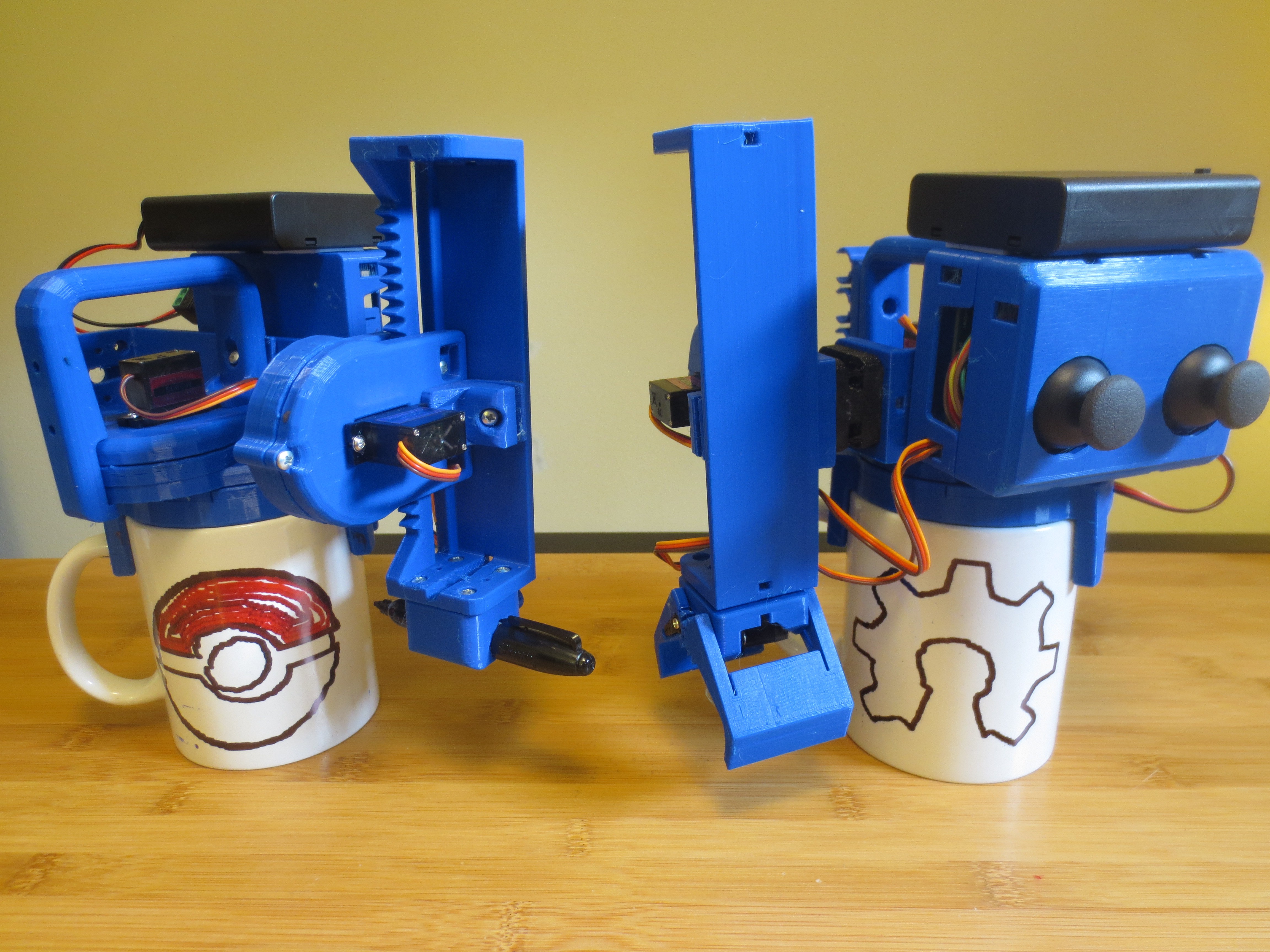
At Left is 'Basic kit', At Right is 'Basic + Expansion Kit'
PokeBall GO! You can draw with multiple colors if you set it up as two drawings & change the tool. The repeatability of this thing surprises even me!! (it traced the perimeters twice)
*Programming Updates: Ive gotten the bluetooth code & Dual joystick controls turned on too! Video of this thing in action here: https://www.facebook.com/michael.p.graham/videos/10156037951901379/
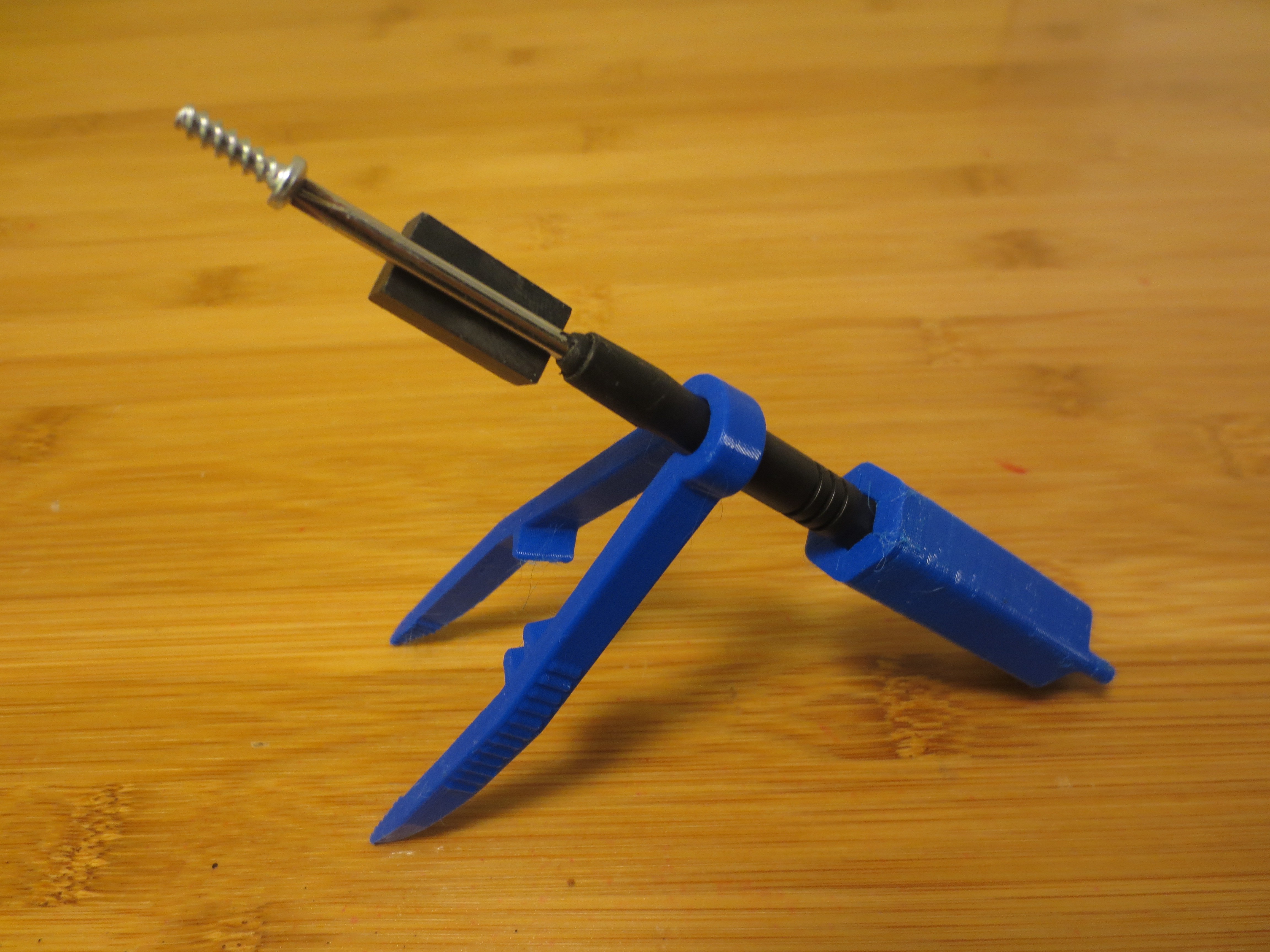
I wanted to take a second to show off my attention to detail here. The pic above is ALL the tools needed to assemble a TinyCNC. There is only one type of screw used everywhere, and the magnet keeps it attached to your driver to make it easy to handle. The screwdriver has a removable handle which also presses the servo horns on. And the tweezers are for routing cables and double as a ratchet-like handle attachment for the screwdriver :)
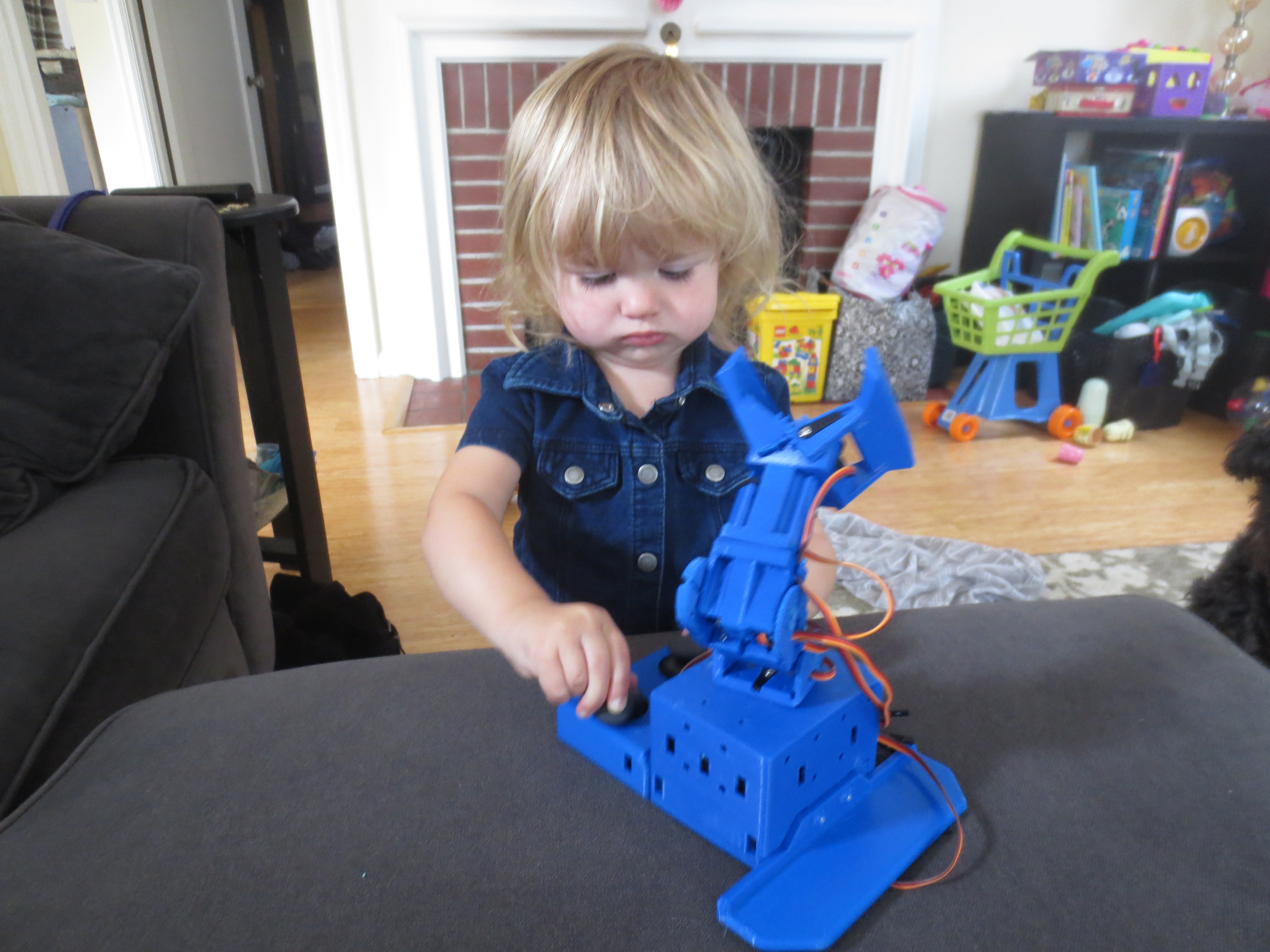
My favorite person playing with my favorite toy!

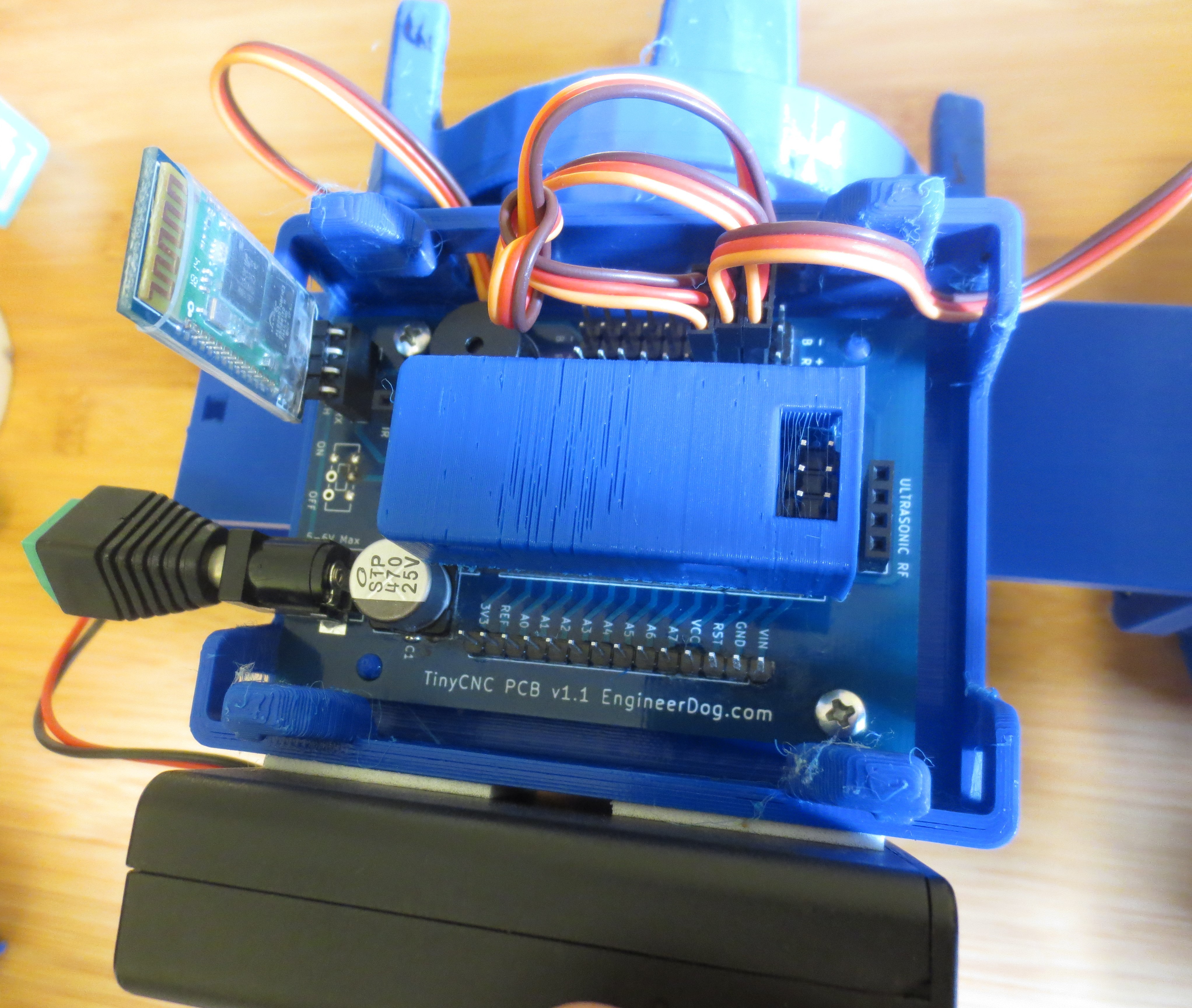
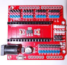
And finally, Showing off the customized PCB. Originally I was going to use the ubiquitous red colored Nano Breakout from China but I learned that even though its cheap, it is too limiting! The servos are driven THROUGH the nano's 5V output so it is limited on current & voltage in that way.

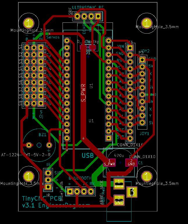
TinyCNC PCB is MUCH better than ol' red board. Note that this work is derived from MePed pcb by Scott Pierce at SpierceTech. He shared his work open source and I picked it up and adapted it to better suit my needs and per his license am also sharing it open source.
*My contributions: Additional pins for attaching 2 joystick controls. Added a Buzzer. Shifted components around to suit my container. Moved the bluetooth headers to block the nano's usb port when it is installed so the user doesnt try to have usb & bluetooth on at the same time (which doesnt work!) Removed i2C & ESP232 connections, & 3.3v power supply components as a cost reduction. Removed the on/off switch as a cost reduction. Updated traces to minimize the path resistance going to the servos to squeeze every last drop of power!
This PCB runs the servos directly rather than through the nano. Not only does this give them more power, but there is a safety benefit. When you plug in just the USB cable to the china board it will attempt to drive the servos while you program it, the USB can only provide ~500ma current so you better hope those servos arent stalled! This PCB separates the two so it wont move while you try to program it!
Also of interest is that Scott designed the board to run just off 6v power input. Which means he had to get clever and use a diode to limit the input voltage to 5V +/- 0.5V and power the nano through its VCC. The risk was selecting the desired voltage drop so that the board doesnt brown out or burn out if you connect different types of batteries to it.
Also of note, in the interest of squeezing out power Ive learned that the servos power output is a square function of their operating voltage, so every little bit extra goes a long way! I power Mug-O-Matic with 4x AA Energizer Ultimate Lithium batteries. They arent rechargeable but they last a long time and dont sag on voltage as they age so they are totally worth it over alkaline or Nickle-type rechargeable.
-
Project Update 2Sept2018
09/03/2018 at 01:33 • 0 commentsFooling around with toys & discussing the challenges + plans moving forward.
-
A Review of Design Decisions
08/30/2018 at 05:13 • 0 commentsIve been working on this project for many months now and there is still much to do but the end is in sight!
In this post I thought it would be interesting to reflect how this project got here by sharing a summarized timeline of development milestones. Often when such a thing is done over time the details on the process are lost, but fortunately I have kept great notes in my google drive!
***Timeline of Design Decisions Chronically starting Jan 2018.***
*Idea Phase- My nagging interest to build 'a robot that builds other things'. Idea for hobby servo based drawing robot sparked by Makerblock's work on Thingiverse.
*Problem Statement- 'Design a profitable robotics kit that encourages kids to persue STEM interests.' Per that goal, the kit should be:
>Replicatable & Affordable- So others can copy this work.
>Unique: To be inspiring.
>Hands-on: Is critical to the learning process
>Expandable: Customization increases user engagement
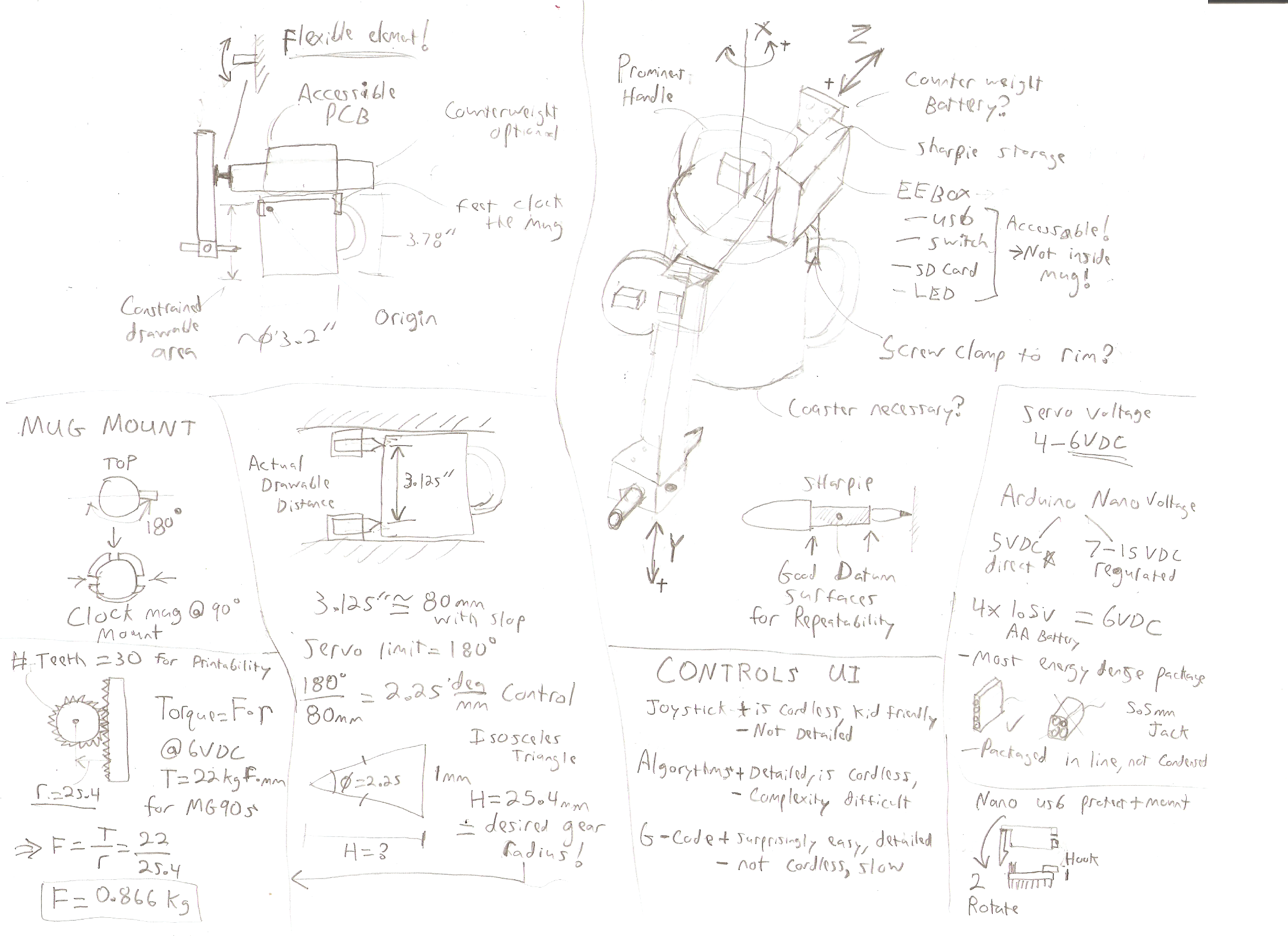
>Open source: Because I am basing some work on open source SW & electronics and I am respecting their license, and can benefit from help by others,and giving things away for free facilitates advertising.Concept drawings: (Originals done on scraps & on different mediums over time. This image is many design considerations condensed nicely.

*Decide on the name "Mug-O-Matic" because its fun :) Stuck with it!
*Research for existing projects similar to this to see if I'm reinventing the wheel. Most useful finds were inspirational but nothing else out there does what I want to do.
*Begin design work. Find a ubiquitous coffee mug. Take measurements to determine necessary drawable extents for actuator (80mm). Spec & order most likely hardware to be used.*Utilize hardware & model elements from my SimpleSumo Robot project to get started quickly.
*Make high level design architecture decisions and set them in stone:
>Toy to use sharpies (mini's specifically.)
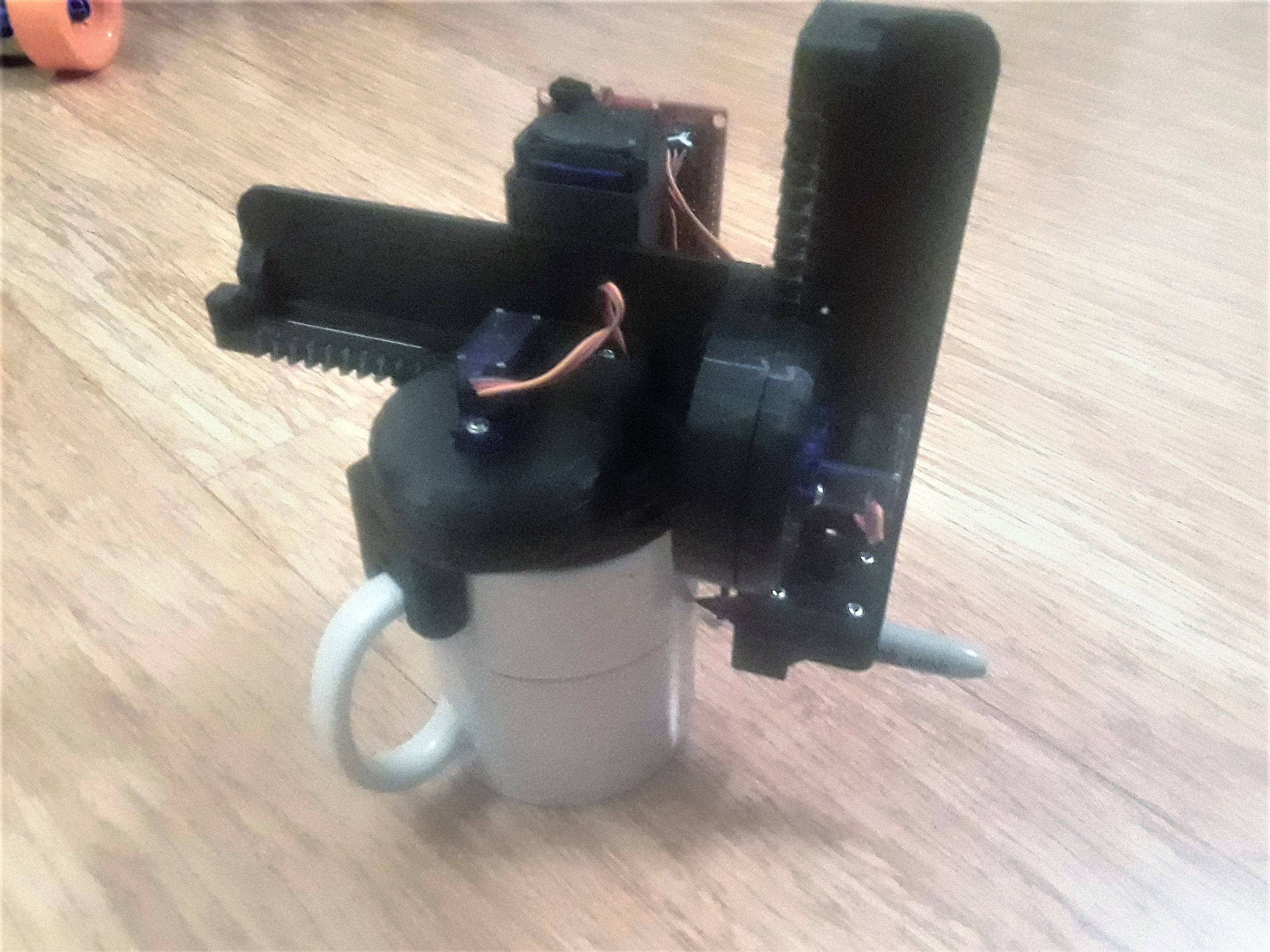
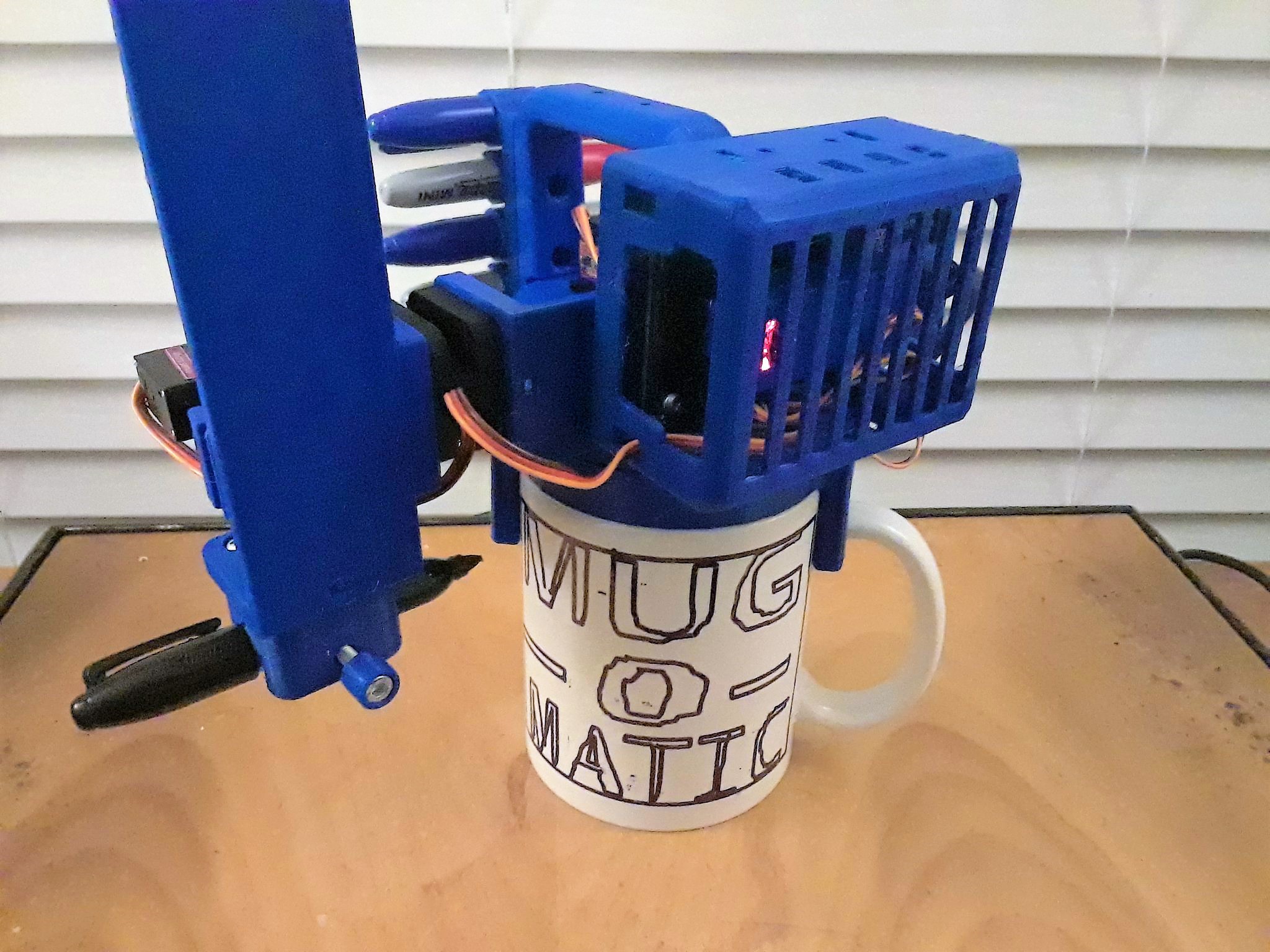
>Mug to be oriented upright with robot sitting on top. I considered setting the mug on top of the bot to segregate the degrees of motion and improve mechanical stability during drawing. BUT the overhanging crane arm is distinctive and looks WAY cooler in action which matters more for a toy!
>Arduino & batteries cannot sit inside of mug. Because there is no space, because you need to be able to access the USB cable to the computer, and because it would enable you to dunk the electronics if you weren't careful!*Research for existing linear actuators. Come up short & start my design from scratch.
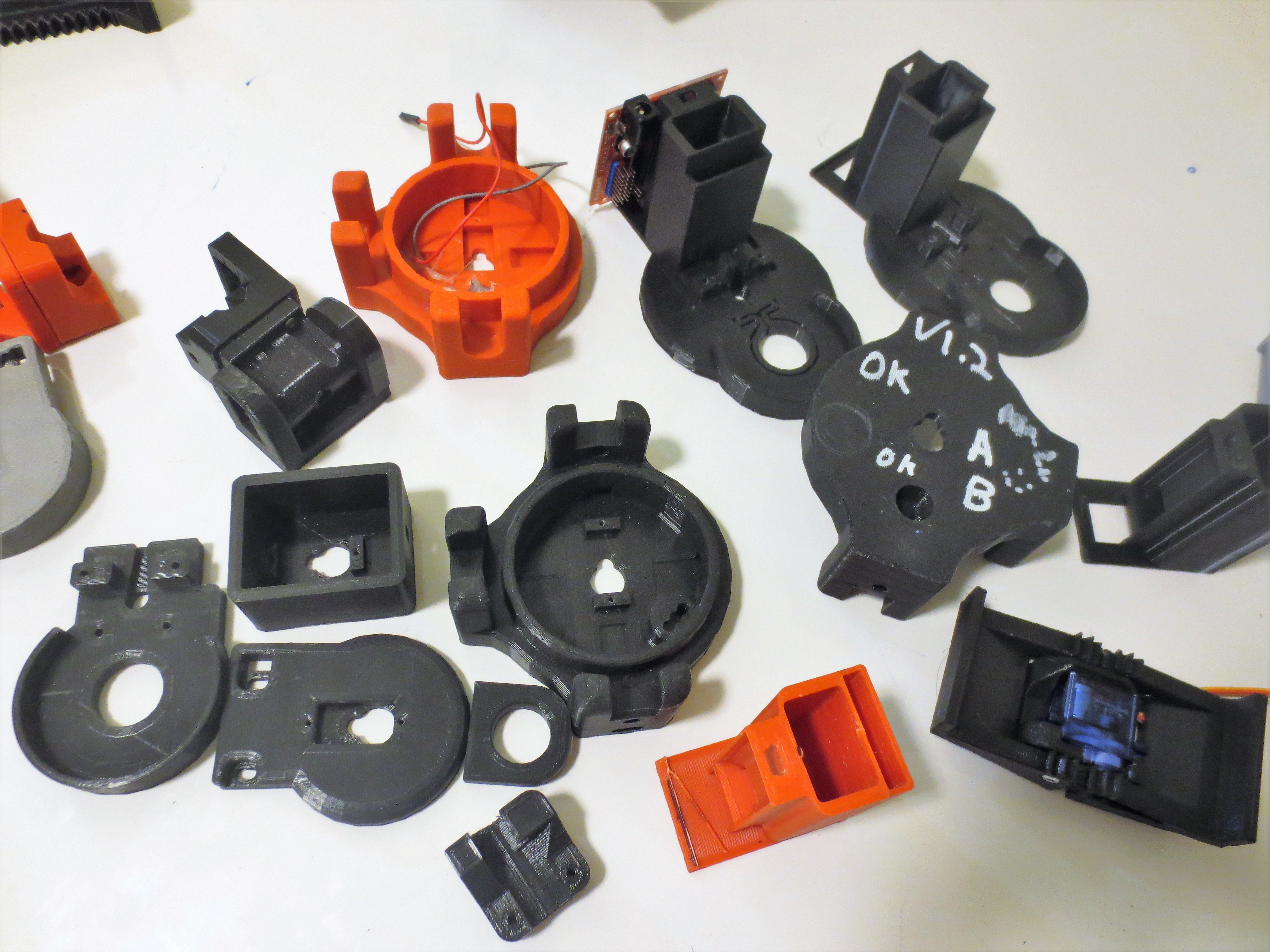
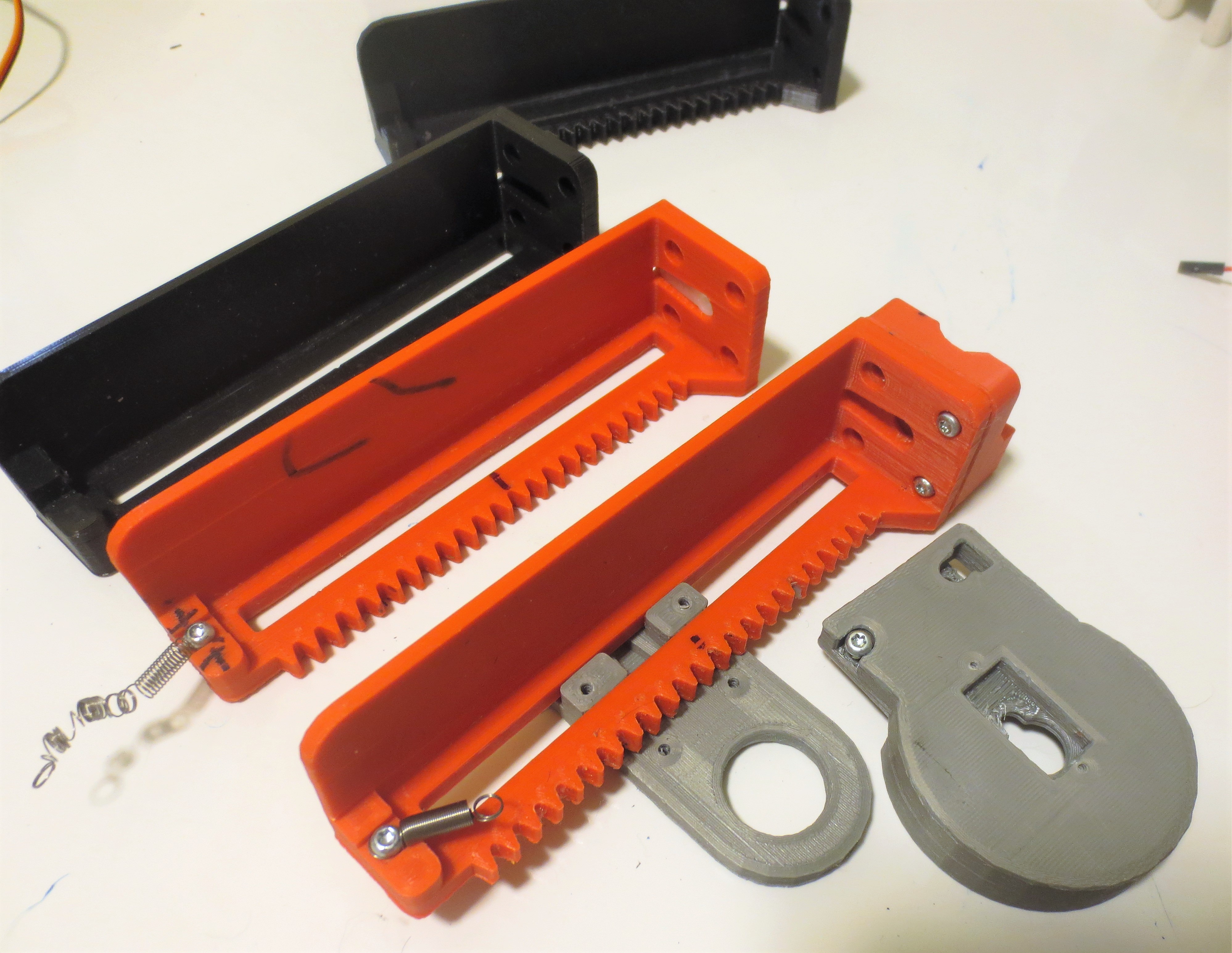
*Prototype assy #1. Very rough. The servos did not have enough power to move the actuator. Assembly freezes up. Asymmetrical parts unsightly. Focused on improving mechanics of the printed parts. (I threw out a lot of prototypes, this is what I had left!)
*Discover that the common arduino nano breakout pcb I was using limited the current that could flow to the servos. Begin searching for other options.
*Realize that modularity would save me effort because the Mug-O-Matic uses 2 linear actuators.
*Realize that modularity would enable a whole bunch of other cool creations. Begin the great distraction of creating the rest of the Tiny_CNC_Collection.
*Repeatedly iterate individual parts to test fit,form, function, printability, etc.
*Thought of the layout for the Post-It-Plotter.
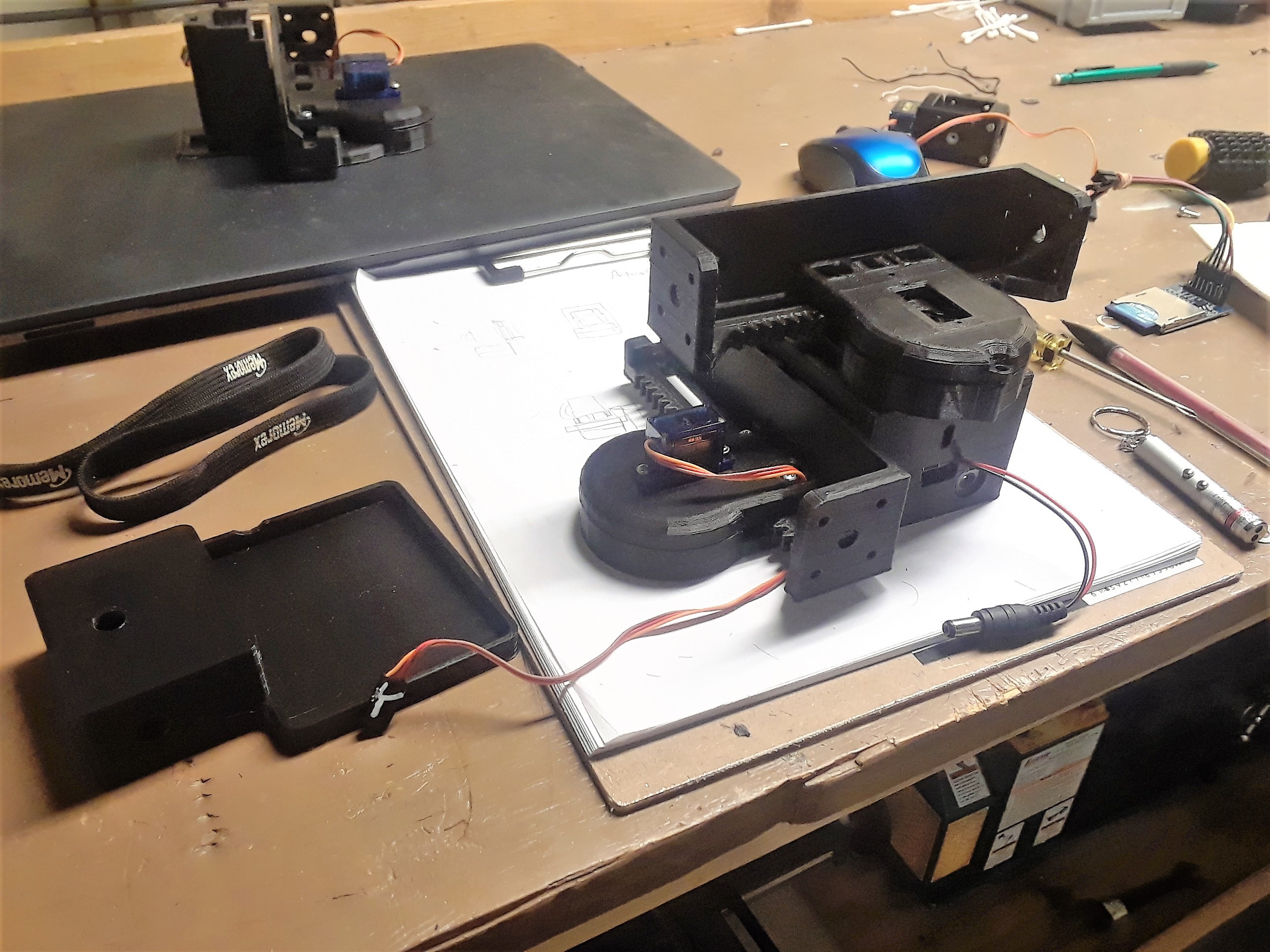
*Prototype assy #2: Getting better. But still had a hard time drawing vertical lines. Realized that I needed to add a flexible element to free the vertical axis from dependence on high 'pen to mug' accuracy to relieve excessive load.

*(You can see the arduino layout is much different than what I ended up with!)
*Lots more repeated iterations of individual parts and sub assemblies. All 3d models custom designed. Enjoyed plaing with gripper & different actuator designs & imagining different uses for a tiny CNC.
* Realized need for line segmentation algorithm to prevent momentum caused overshoot issues.
*Determined that MEPED PCB is a great option for this robot.
*Decided to design new PCB based on MEPED PCB. (Also a good excuse to learn KiCad.) Make design adjustments to remove unneeded functions, move things to improve fit, add elements for desired functionality. PCB design quoted, PCA BOM pending.
*User testing- Play with prototypes with middleschool robotics club. Determined ciritcal need to optimize designs + tools for small inexperienced hands and to create more concise & user friendly instructions.*Complete mechanical BOM. Decide on use of batteries > wall wart for standard device. Have to find a place to mount batteries.
*Still getting distracted designing fun extra modules & assemblies.Prototype design above. Final Design below.
*Kickstarter tease announced on EngineerDog.com. Trying to determine consumer demand for the Mug-O-Matic. Still not 100% sure if I can pull it all off.*Decide to pick solid blue PLA+ as the offical material & color scheme. Black was considered because it looks professional, but it is hard to photograph. White was considered because then you can paint it any color you want, but painting is tedious and white lacks personality.
Blue is more playful and more suggestive that this is a toy. All parts being the same color & material helps the logistics of producing them as kits. Parts are designed to work in any material but PLA+ is a good balance of printability, cost, rigidity, and finished appearance.
Similiarly, settling on official layer thickness of 0.2mm balances finish quality & printing speed.*Prototype assy #X: Completed design optimization + verification. Optimized line segmentation drawing algorithm. :) Realized stall detection impossible. :(
*Lay out & photograph step by step assembly of different robots. Whiteboard style instructions.
*Enabled Gcode functionality! Enabled basic bluetooth functionality! Robot kicks butt!
*Realized the benefits of grease for vertical linear actuator. (A tiny addition with outsize benefits!)
*Confidence in design is skyhigh. Designed Mug-O-Matic Logo in MS Paint in 2 hours late at night + Create Business Cards.
PENDING "TO-DOs" by Oct 22:
*Enable joystick functionality (Nice to have not required.)
*Enable dot matrix functionality- (Nice to have not required.)
*Complete detailed instructional video to go along with images. (Must Have)
*Makerfaire PDX- Toys in lots of Kids Hands! (Must do)*World makerfaire appearance! (Nice to have.)
*Final Video of FULL DEMO + brief demo of alternative assemblies of Tiny_CNC_Collection . (Must do)
*Shareable files (HaD) + Buildable BOM(Google Docs) (Must Do)
*HackADay Prize Ends Oct 22.
*Kickstarter for Improved PCB's + component volume order. (Still gathering followers so timeline TBD) -
2 steps back...1 leap forward!
08/14/2018 at 05:15 • 0 commentsThis weekend has been quite the journey. With my wife & kid out of town for a few days and left to my own devices, I ended up working myself sick. Literally. :/
Saturday was spent drudging through failure, frustration, & a nasty flu. But only a couple days later I have finally accomplished enormous success!
The Mug-O-Matic (MoM) can now successfully draw with G-code using a simple replicatable toolpath! Leveraging a processing program & gcode reader based on work by Makerblock, Heindal, & Oliv4945, I had to modify their work significantly to suit my specific needs. In the end the path is: Use Repetier Host + Slic3r to slice a flat 3d model & export gcode to desktop, Use Processing to send data over serial (usb tethered), have the arduino interpret said data line by line to print. Video to follow. On the downside more tuning is clearly required, the drawings resulting from gcode are much sloppier than I had hoped and the act of drawing is slow. Too soon to say how clean I will be able to get it. Im still happy though!
Almost as good is that I successfully completed the line segmentation algorithm. Now when you tell the device to draw a long line from one side to the other, (at any angle/direction) it will segment that line into the minimum draw-able resolution of 1mm and move the specified distance in the maximum number of increments. The result is a slower motion that negates the effects of rotating mass and prevents target overshoot!
The backlash compensation code is also up and going successfully. The effect is subtle because the backlash was subtle, but it works and I am satisfied.
Other learnings & updates in bullet form:
*Unfortunately, this device can never do stall detection as I had originally hoped. While hobby servos do use potentiometers, they are not physically wired to provide feedback to the arduino. The feedback is simply unavailable. (Arduino servo.read command just tells you the last position you wrote to the servo, not the actual angle it is which may differ if the device as been stalled.)
*I am designing a new Tiny_CNC_PCB specific for this project based on the MePed board by Scott P. Though his work is great for this, there are some minor variations for cost & fit & function that I want to implement. To be honest I have never designed or ordered a PCB in my life, but have wanted to learn the skills. This has been a great opportunity to learn KiCad and pcb design via remixing rather than starting from scratch. So I thought I had it finished and I even have a prototype supplier lined up, only then I decided that I need to update the design a bit more...This perfectionism is a trend with me that is great for getting a job done well, though timeliness can suffer. This is what has made the 3D models take so long to complete.
*My 3d modelling has also been slowed by the fact that designing all 60 components to be modular and function with each other as a set means that I have to be aware of every possible mechanical configuration for interferences and such. Physical testing with all parts in hand of the latest rev is very important. Often I find problems caused by very subltle issues like two seemingly perpendicular surfaces actually being 179.5 degrees apart, thereby stalling a hinge. The devil is in the details!
*The software processing.org/ is really powerful stuff for easily making a custom robot controller GUI and I am definitely going to spend more time learning the intricacies at some point. For now knowing the basics is adequate.
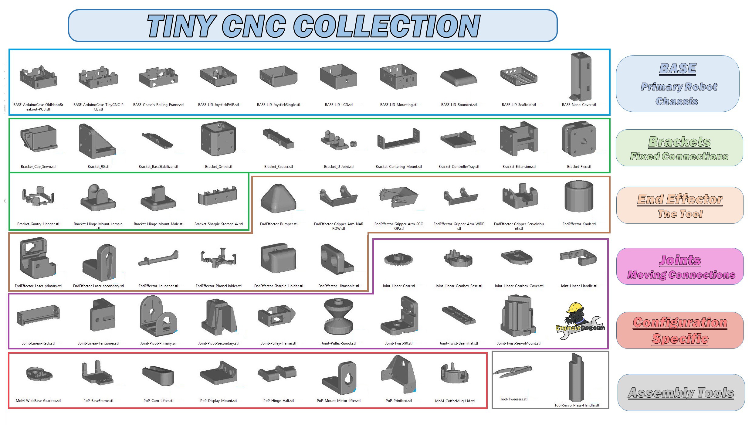
*I have been releasing 3dmodels to thingiverse as I get the time to photograph the assembly process and watermark the images. (Yes this project IS still 100% open source, and if people want to make their own from scratch you are welcome to do so, but the attribution aspect is important to me.) Here is that growing 3d model collection:https://www.thingiverse.com/MechEngineerMike/collections/mugomatic-tiny-cnc-collection
*Here is the latest artwork to help describe how the components of this collection go together.

*Also of note: As an alternative to gcode drawing I am developing dot matrix drawing capability in parallel as a hedge against failure. This thing WILL draw custom stuff one way of another :D Below is an array of 1 & zeros generated from an image of my blog logo. My experiment suggest that I will be able to write a program that operates very much like a mechanical typewriter moves, line by line seeking that 1 to make a dot. This method will produce discontinuous lines BUT it wont smear either.
As you can see the words are simply scrambled in the process, the logo is too detailed to be scaled as a whole down to a 1mm minimum movement scale.
-
Video Demo Project Update
07/29/2018 at 18:25 • 0 comments -
Updates to project vision & plan
07/20/2018 at 05:19 • 0 commentsThis is the first update since I was awarded the $1000 for the first round of the HaD Prize, so thanks for that! I took some time to look through the winners so far in this years Prize (and prior years) and I have to say that was a humbling experience.
People on HaD make some of the most amazing DIY projects I've seen on the internet, and so part of me feels like bringing my little toy to the party is a bit like a knife to a gunfight lol!
Except, I do think this little toy is exactly the type of thing that this challenge is for.
The purpose of the Prize is to show the good that technology can do and to build hope for a better future, and where better to find that inspiration than the next generation of scientists and engineers?
Tell you something, I love meeting smart kids! I go to as many Makerfaires as easily possible and I recently decided to sponsor a local public middle school robotics club because I see them as a valuable asset to the community. Its encouraging to see young people with technical interests who are clearly destined to grow up and make useful contributions to society. Not that non-techies don't contribute, but it's the scientists who solve life's big problems and the inventors who create technology to raise the tide that floats all boats. Constructive technology makes life better for everyone and society only stands to benefit from an increased interest in science and the key scientific virtues of honesty & curiosity.
That's also why I love to see how making things is becoming more culturally popular with time. As seen in the growth of MakerFaire's celebration of invention/creativity/resourcefulness, and kids movies featuring techno-optimist themes and tech-savvy hero's, like Big Hero 6, Meet the Robinson's, Cloudy with a chance of meatballs, and similar.
Open source educational toys also have their own role to play in sparking the interest of young minds. Things like the EggBot, MePed, & the MeArm are clever inventions that attract and provide an excuse for a newbie to get their toes wet and develop new skills. And now alongside them will be the Mug-O-Matic and its various configurations!
(Fyi I think up until this update I've made the mistake engineers commonly do when selling an idea. That is, sell features instead of benefits & ROI. This project is not ABOUT the 3d printed linear actuator. Rather, that was a stepping stone, a cool component of a larger work with a more important purpose.)
For this project I chose to accentuate 3 features to solve key problems with currently available edu toys:
*Usefulness: The finished robot should do useful meaningful work as real robots do, rather than exist solely to be cool. Also, as per the contest the robot modules themselves should have a usefulness such that they facilitate others to build incredible robot projects.
*Tinker-with-Ability: As I learned from Invent to Learn, kids learn by doing and are most engaged when they are able to independently experiment rather than just being told what to do.
*Accessibility: Be as easy and affordable to replicate as possible. Replay value is a must. Schools aren't known for being flush with spare resources.
I think the current design is on target for these goals. Here is the current project status:
While I have not been promoting this work much recently, I have basically been spending all my free time developing it. Keeping my head down pulling the cart. I've spent a significant portion of the prize money already gathering hardware to make a few of everything and then some. R&D isn't cheap.
In a nutshell, Ill soon have the essential hardware models in a shareable state. I have a whole construction set of proven easy to print parts that can be rearranged to build all the common industrial robot configurations, or a walking bot, or any other Voltron style complexity a kid would desire.
The Mug-o-Matic & Post-it-Plotter (MoM & PoP? lol) are the stars of the show because these toys enable the user to produce a real & unique output. Customized mugs & sticky notes drawn with a precision, speed, & repeat-ability not achievable the the typical human hand. And even though the builder will follow assembly directions for those bots (only) they aren't robbed of the 'I made this' feeling or opportunities for tinkering & original experiments.
Da Loose Plan:
1. Perfect hardware. -Don't share models until stable so people don't print obsolete parts and repeat my mistakes! (Almost there!)
2. Develop software. -enough to show what this puppy can do.
3. Proliferate design. -Seek feedback/ideas, adopters / collaborators.
4. Perfect software. -Focused on MoM & PoP. (They use the same sw.)
5. Promote. I'll say now that even though this work is entirely open source that I have some profit motivated plans. I'd like to do a crowd funded batch build but I first need to determine if enough people will be interested.*** If you are potentially interested in supporting a crowdfund build then take a second to fill out this survey please & thanks! https://goo.gl/forms/AO6mLvSjEYM33To33
I also have all the connections for putting on a sponsored build/teach event with a local non-profit if I decide that I am up for all that. But for sure I have a table reserved @ Makerfaire PDX 2018 to display this specific project and let kids build & manually control bots with servo drivers & joysticks.
6. Develop sw for alternate configurations.
But how far I try to take it really depends on how it is received. Will it encourage & inspire, or bore confuse and frustrate...? I work in isolation too much and sometimes dumb ideas seem great for a while. :) And as best I can tell people love robot arm type toys & the MoM in motion makes quite the appealing display. This week I was able to let a small group of middle schoolers play with my prototypes. A promising start and I learned a couple things from the experience.
Identified distinct programs to develop:
* 'Teaching' the bot (via 2 buttons & screen module. EASY. enables quick programming for weird configuration bots.)
* Manual control via joystick modules EASY. Enables alternate manual control option favorable to potentiometers.
* Wired or Bluetooth drawing of different list of math functions like a graphing calculator EASY
*Wired or Bluetooth Gcode drawing. HARD
*Wired or Bluetooth dot matrix drawing. HARD
*Bluetooth communication- Smart phone control. HARDSchedule of Updates: mostly a note to self, I know this update is long and few will read it.
1. Share vision & plan (current)
2. Mechanicals:
3. Electricals:
4. Programs:
5. The big day(s).October 22 = deadline to publish: video + BOM + instructions + design files + module IO specs
Well that's where were at now.
-
Video Update #2: Measuring & improving the output precision.
06/11/2018 at 06:53 • 0 commentsWhile controlling the linear actuator can be done without hacking, I've found that doing so has its limitations.
Specifically with my setup the arduino nano has voltage and current limits that prevent the servos from reaching their full potential. Especially when I'm controlling 3 servos simultaneously in a stressful application! This problem manifests in a locked up actuator when trying to make small movements, because the actuator cannot overcome the static friction with a proportioned control designed to only move a small distance.
So I did some experimenting to find a way to power my servos directly from two 18650 batteries while isolating that 7V from getting to my computer's usb port.
In the end the hack was simple, which is the way I like it! This successful experiment will enable my drawing robots to operate with move torque and a greater degree of precision in small movements!
One step closer, yay!
-
Uploaded Accessories & STEP files
06/02/2018 at 07:25 • 0 commentsContinuing from last weeks log I have thought about how to best share the 3d models for this work.
I think since there are many applications of these modular components, each with their own instructions, that they are best shared as their own separate projects on HackaDay. (See end of this post for more new application pics!)
Along that same line of thinking I believe that the small sub assemblies should each have their own project identity as well. This will make following & reproducing the body of work the easiest.
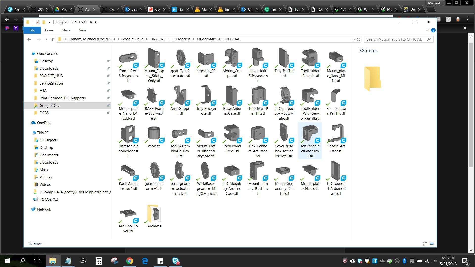
But for now my time is limited so I simply uploaded a compressed folder containing some of the accessories that go with the linear actuator module, as well as a STEP file (universally importable 3d model) of the actuator assembly itself.
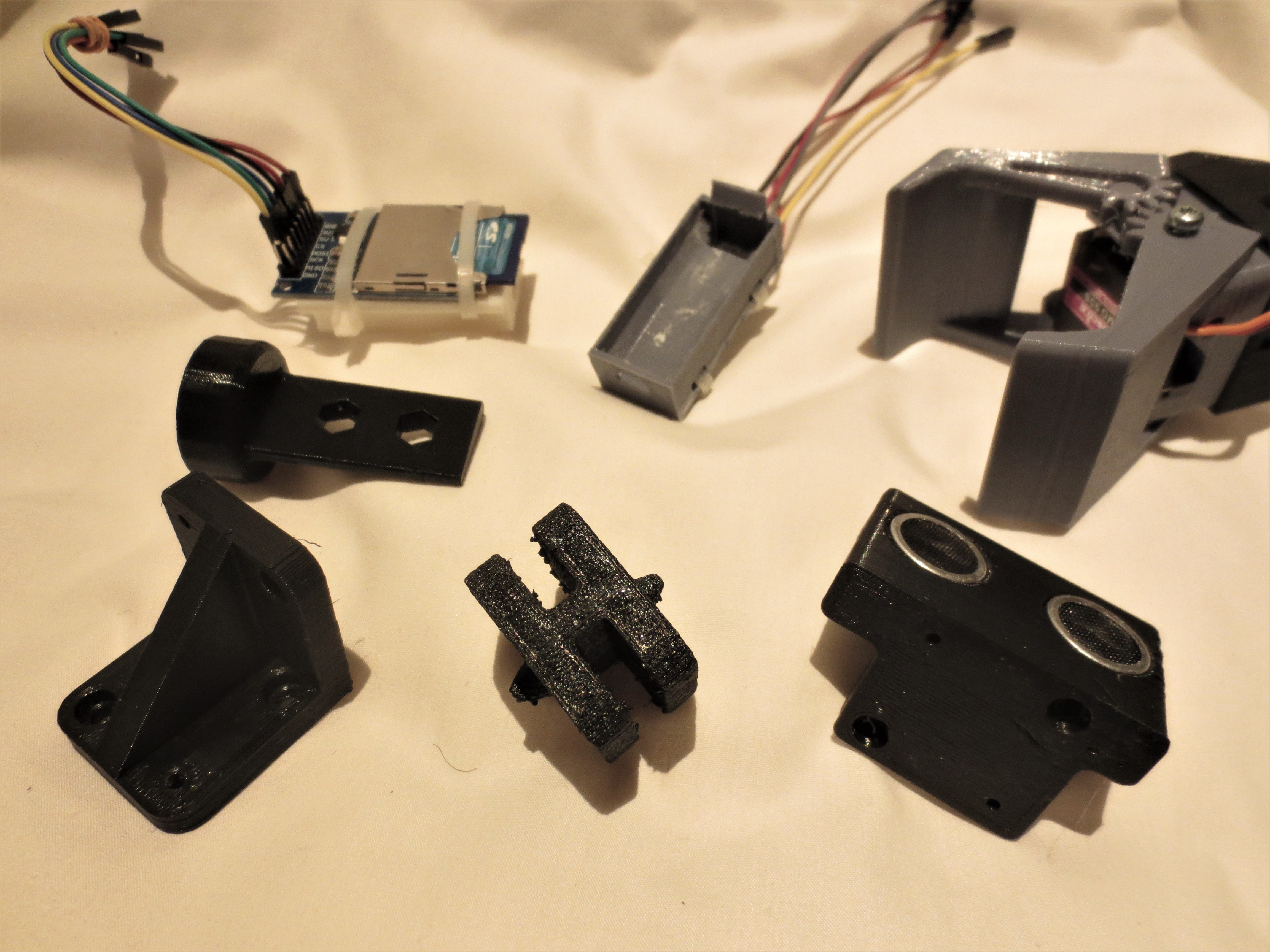
Seen below top left are special mounts that clip onto an arduino nano without the need or screws and they hold bluetooth & sd card modules. going CCw is a gripper, an ultrasonic sensor mount, a flexible joint, a hard 90 deg joint, and an assembly tool for pressing the servo horn on.

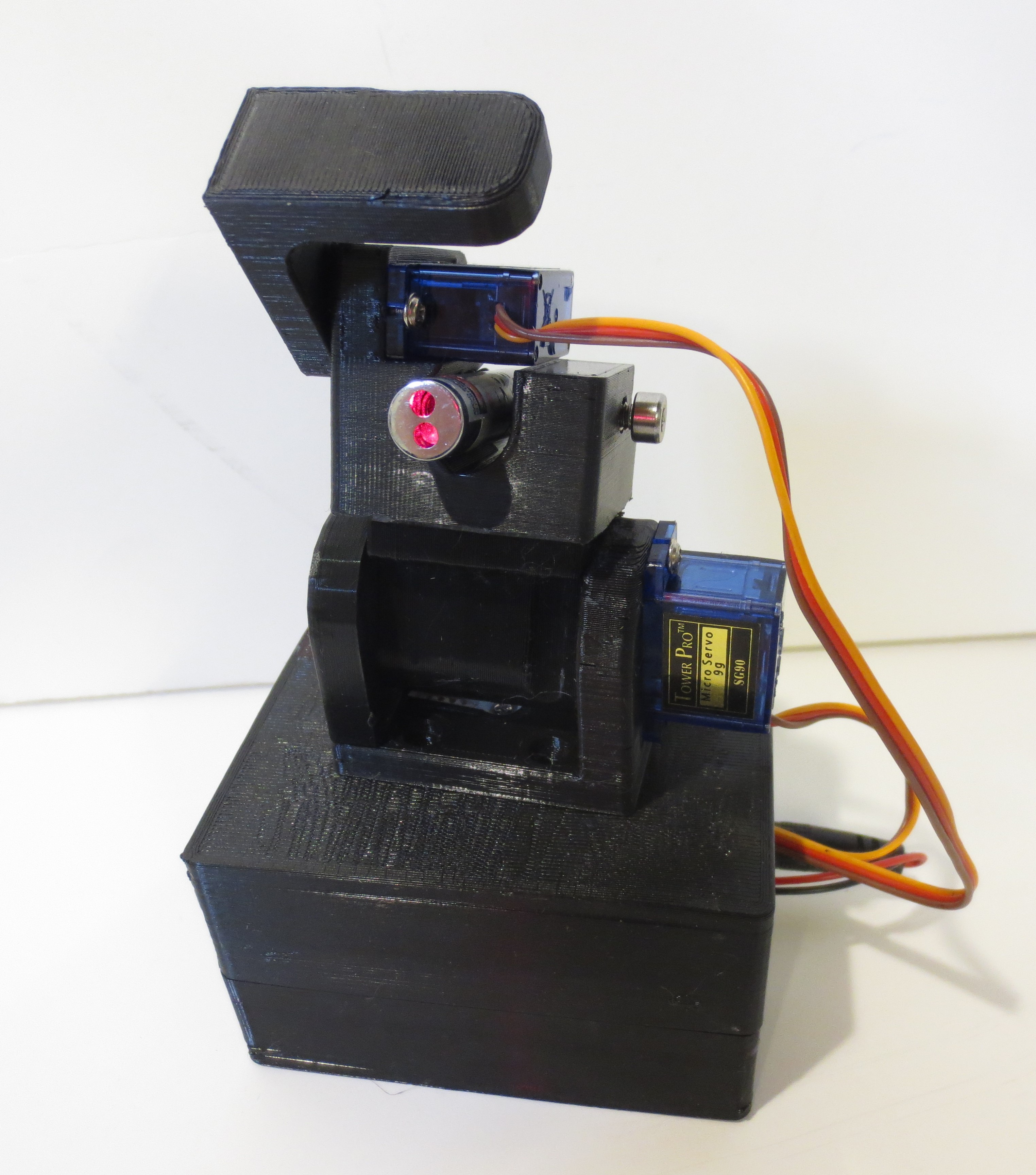
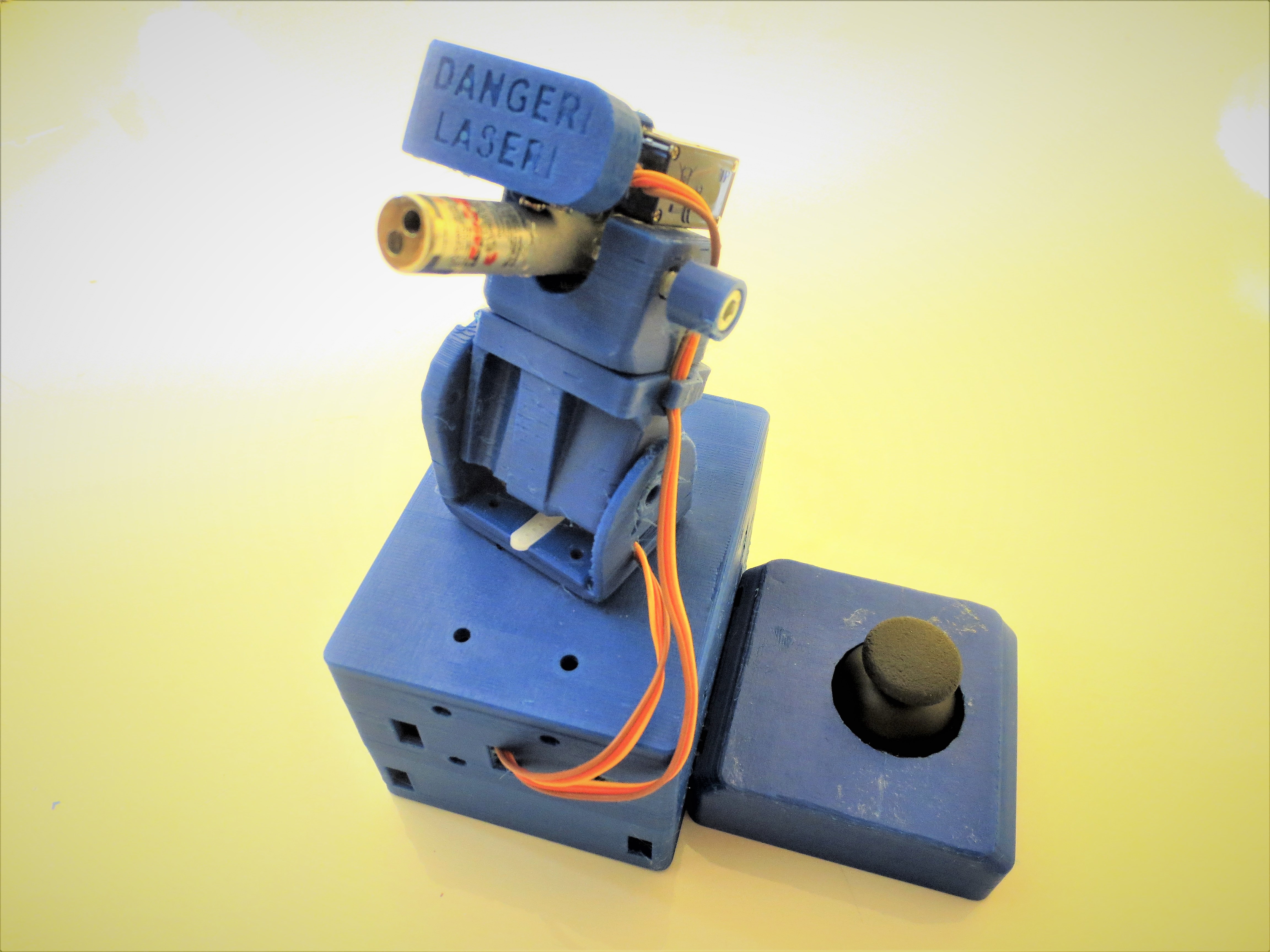
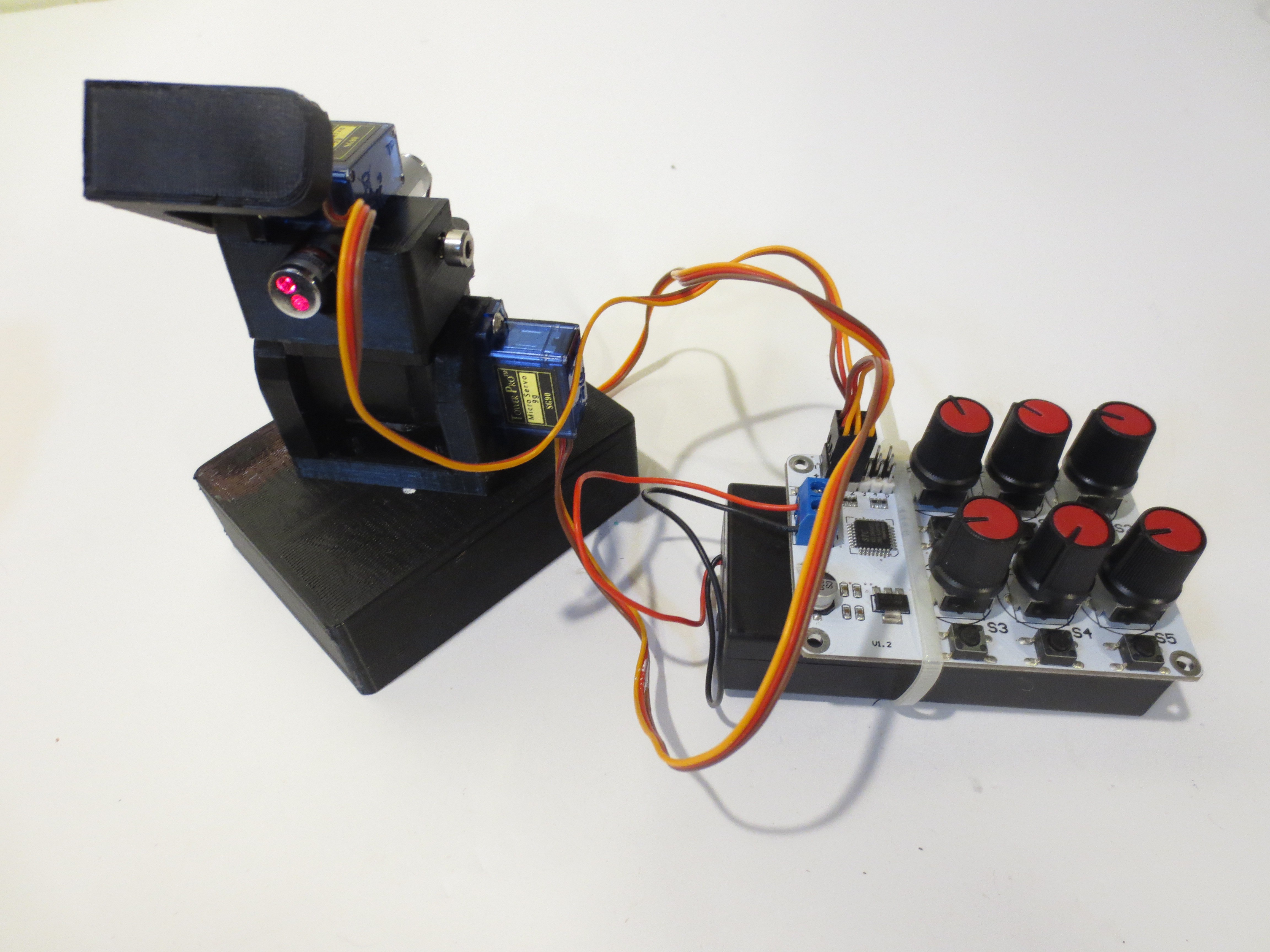
I'll leave off with a neat picture of a laser turret I just finished up. It does not contain the linear actuator, but the components of this turret are compatible with the actuator mounting pattern so all the pieces could be used together to make something else!
The hinged joints in the turret shown below are also designed to be robust, rigid, and easy to 3D print like the actuator.
-
Models complete! Testing in progress, Challenges encountered.
05/22/2018 at 02:22 • 0 commentsI am finally confident enough in my hardware to release all of the 3D models associated with this body of work! Every single model has been printed and tested to my liking.
However, I am dealing with 3 challenges at the moment.
1. Sharing too much makes the work hard to follow. I need to figure out a way to share these models without making it confusing as to which part goes where in which application...
You see, sometimes (ok frequently) I get creatively carried away and at this point there are 39 different parts in this set! (And the arduino cases are compatible with the SimpleSumo robot set to boot).
The Hackday.io site does not allow you to sort your uploads into folders so I will have to upload everything into one long flat list and that will be hard to follow. Hard to follow = hard to replicate = failure of a primary project goal...
For now my plan is to be very careful with my naming conventions, and to provide separate build lists for the assemblies, & screenshots with callouts to identify which part goes where.
2. My drive system is underpowered. Through research & testing I realized that the arduino nano & breakout board that I love so much are actually limiting factors in the functionality of the drawing robot applications.
As it turns out, the breakout board does not have its own 5V voltage regulator and instead relies on the nano's built-in regulator to power all the 5V rails. I believe it is 1 amp maximum divided among the 3 servos and the nano itself.
The result is that the post-it-plotter application has a hard time completing small movements without stalling. The mug-o-matic coffee cup application works OK though because it doesn't require as much torque to operate. Clearly, I am operating at the edge of the capabilities of my equipment.
Ive tried to get cute & write the code to shut off the Z axis servo when it is not in use. This has helped to a limited extent. I can do that because these drawing robots are 2.5 axis CNC's in practice because the pen axis is only used in one of two extreme positions. Draw or no draw.
Indeed, when I plug the servos into a stand alone servo driver with two 18650 batteries as I did in my demo video, they are exploding with torque.
One way I can get around this issue is to program the robot to draw via dot matrix. That is, drawing by making lots of dots instead of dragging the pen to make lines (which requires more torque.)
3. Coding is hard. While I am strong at mechanical design & documentation, my coding skills are comparatively soft and flabby. Making the robot do the cool things it will physically be capable of is a challenge.
For now the robot can draw simple shapes via a mathematical algorithm written on the arduino. Fairly simple stuff. But my vision for the project includes drawing the EngineerDog logo on the side of my coffee mug which will require a more complicated solution.
To draw via dot matrix I can convert images to a 2D array of 0s & 1s via a free website here; https://www.dcode.fr/binary-image However, getting the arduino to read that data is the issue. I can literally paste the array directly into the arduino code but I'd have to manually add text delimiters to make it work so thats a no go.
To read the dot matrix or G-code I could send the data over serial using "Processing" or an SD card, but it is easier said than done. For that capability I will have to lean heavily on the code written by MakerBlock, whose work inspired this project.
Im thinking the easiest cool thing I can accomplish within the time frame of this contest may be the addition of bluetooth control. Adding a common HC-05 bluetooth module is easy and I can use a nifty freemium program called Robo-Remo to drive from my phone. https://www.roboremo.com/
More time/sweat is required.
Mug-O-Matic: A Modular Tiny CNC
Open Source Reconfigurable Robot Arm for Learning STEM. Make It Your Way!
 Michael Graham
