Makerfabs
-
Updated to V3
08/30/2019 at 09:24 • 0 commentsUpdates in the version 3:
1. Power circuit update: previously a 3.7v battery is needed as the A9G power supply.
in the new version 3, the module can be powered either by battery , or directly by USB.
2. Battery voltage Monitor, to check the battery voltage
3. USB voltage monitor, to check if there a USB power connected;
4. 3.3V DC-DC module updated to 1A Version
5. Power switch added , to power on/off the whole module.
-
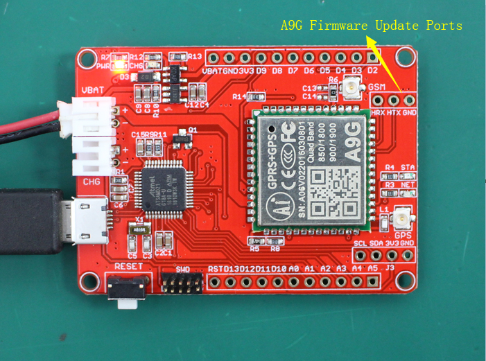
A9G firmware update ports
12/12/2018 at 07:04 • 3 commentsRecently we got many customers’ feedback about the A9G module, that how to upgrade the A9G firmware, as Aithink released new version firmware.
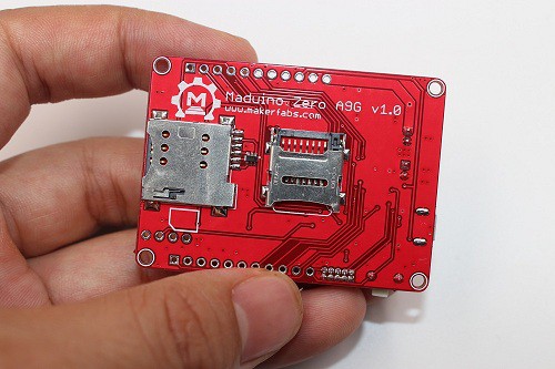
That we released the Maduino A9G 2.0, with A9G module firmware upgrade port added:
![]()
1. The A9G firmware upgrade port:
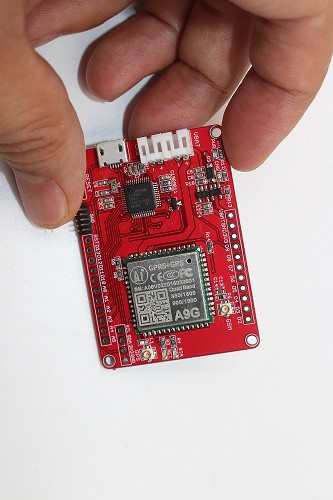
The A9G uses a simple UART port for firmware updates. In our new released Maduino A9G 2.0 version, you can find it here:
![]()
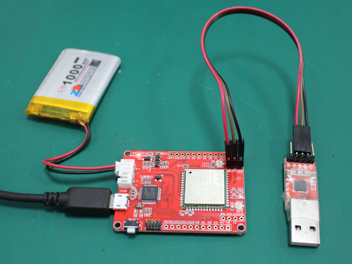
And, you may need a USB2UART convertor, such as the CP2104 Convertor.
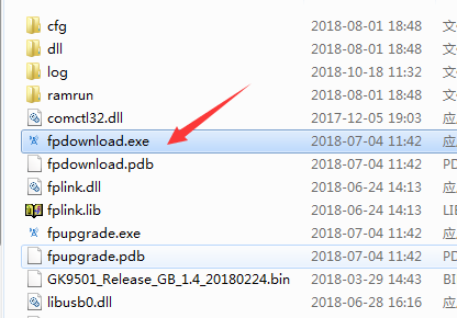
2. Download the Aithink firmware upload tools and the latest firmware for A9G board at: http://www.makerfabs.com/desfile/files/A9 A9G firmware and tool.zip
3. Connect the USB2UART to Maduino, as below:
A9/A9G 3.3V USB to TTL
HRXD <-> TXD
HTXD <-> RXD
GND <-> GND
![]()
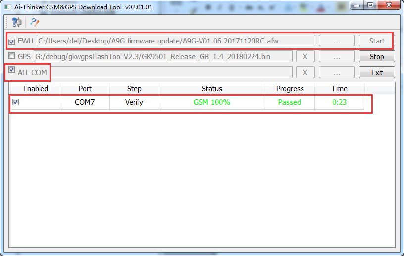
4. Open the firmware update tool, select the latest version of firmware, and click “start” to start the upgrading.
![]()
![]()
![]()
-
GSM Testing
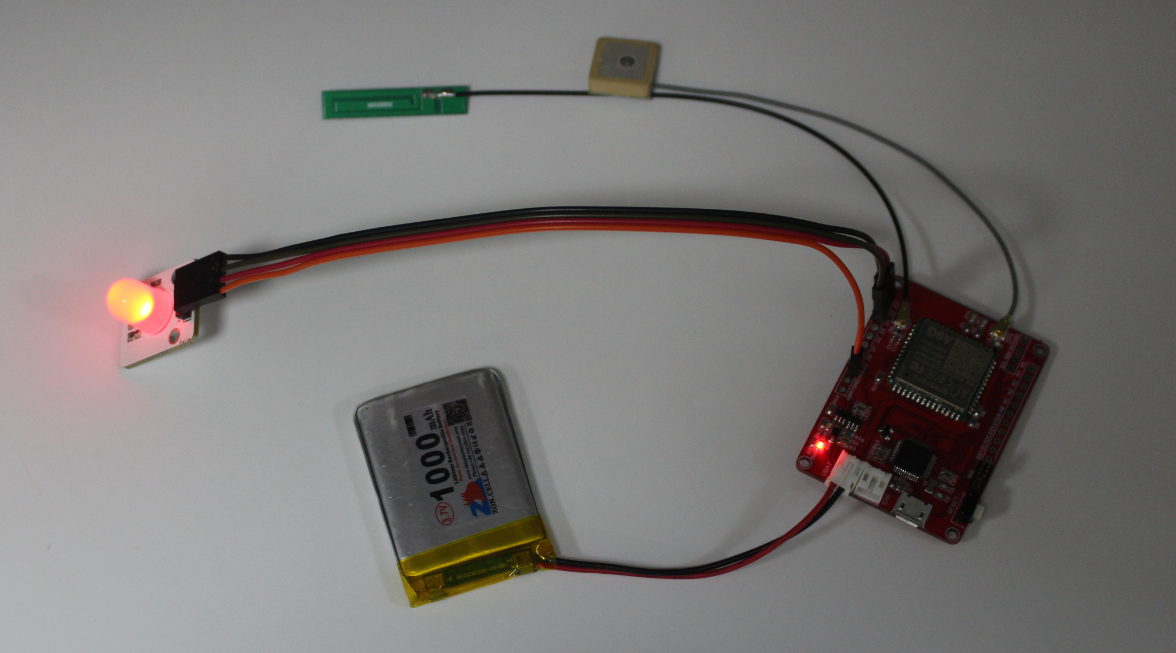
06/07/2018 at 11:10 • 0 commentsOk, I admire that my coding poor, a simple code, that the Maduino zero receives the SMS from a phone, and then controls the connected LED on and off..... The LED turns on when receiving my message:"onr":
![]()
#include<stdio.h>
#include<string.h>
#define DEBUG true
  int pon=9;
  int poff=6;
  int lowp=5;
 int LED_R= 2;
 int LED_G = 3;
 int LED_B=4;
 String msg = String("");
 int SmsContentFlag = 0;
void setup()
{
  pinMode(pon, OUTPUT);
  pinMode(poff, OUTPUT);
  pinMode(lowp, OUTPUT);
  digitalWrite(poff, LOW);
  digitalWrite(lowp, HIGH);
  digitalWrite(pon, HIGH);
  String msg = String("");
  int SmsContentFlag = 0;
  pinMode( LED_R, OUTPUT );
  pinMode(LED_G, OUTPUT );
  pinMode(LED_B, OUTPUT );
  digitalWrite(LED_R, HIGH );
  digitalWrite(LED_G, HIGH );
  digitalWrite(LED_B, HIGH );
  SerialUSB.begin(115200);
   while (!SerialUSB) {
    ; // wait for serial port to connect
  }
  Serial1.begin(115200);
   poweron();
  GprsTextModeSMS();
}

void loop()
{
    char SerialInByte;
    if( SerialUSB.available())
    {
        Serial1.print((unsigned char) SerialUSB.read());
    }
    else if( Serial1.available())
    {
        char SerialInByte;
        SerialInByte = (unsigned char) Serial1.read();
        if( SerialInByte == 13 )
        {
          ProcessGprsMsg();
         }
         if( SerialInByte == 10 ){
         }
         else {
           // EN: store the current character in the message string buffer
           msg += String(SerialInByte);
         }
     }
}

void poweron()
{
     int i=0;
     boolean result = false;
     digitalWrite(pon, LOW);
    delay(3000);
    digitalWrite(pon, HIGH);
    delay(15000);

     result =  Serial1.find("OK");
     if(result)
    SerialUSB.println( "Please send sms to control your device!" );
    else
  {
               for(i=0;i<10;i++)
              {
                      Serial1.println("AT");delay(500);
                     result =  Serial1.find("OK");
                     if(result)
                     {
                        SerialUSB.println( "Please send sms to control your device!" );
                       return;
                     }
         }
         }
}
void ProcessSms( String sms )
{
   SerialUSB.print( "ProcessSms for [" );
   SerialUSB.print( sms );
   SerialUSB.println( "]" );
  if( sms.indexOf("onr") >= 0 ){
    digitalWrite(LED_R, LOW);
     SerialUSB.println( "LED Red ON" );
//    return;
  }
  if( sms.indexOf("ong") >= 0 ){
    digitalWrite( LED_G, LOW);
     SerialUSB.println( "LED Green ON" );
//    return;
  }
    if( sms.indexOf("onb") >= 0 ){
    digitalWrite(LED_B, LOW);
     SerialUSB.println( "LED Blue ON" );
//    return;
  }
    if( sms.indexOf("offr") >= 0 ){
        digitalWrite( LED_R,HIGH);
     SerialUSB.println( "LED Red OFF" );
//    return;
  }
  if( sms.indexOf("offg") >= 0 ){
    digitalWrite(LED_G, HIGH );
     SerialUSB.println( "LED Green OFF" );
//    return;
  }
    if( sms.indexOf("offb") >= 0 ){
    digitalWrite(LED_B, HIGH );
     SerialUSB.println( "LED Blue OFF" );
//    return;
  }
}

// EN: Request Text Mode for SMS messaging

void GprsTextModeSMS(){
   Serial1.println( "AT+CMGF=1" );
}

void GprsReadSmsStore( String SmsStorePos ){
  // Serial.print( "GprsReadSmsStore for storePos " );
  // Serial.println( SmsStorePos );
   Serial1.print( "AT+CMGR=" );
   Serial1.println( SmsStorePos );
}

// EN: Clear the GPRS shield message buffer

void ClearGprsMsg(){
  msg = "";
}

// EN: interpret the GPRS shield message and act appropiately

void ProcessGprsMsg()
{
     SerialUSB.println("");
  //  Serial.print( "GPRS Message: [" );
    SerialUSB.print( msg );
//    Serial.println( "]" );
    if( msg.indexOf( "Call Ready" ) >= 0 )
   {
        SerialUSB.println( "*** GPRS Shield registered on Mobile Network ***" );
       GprsTextModeSMS();
   }

  // EN: unsolicited message received when getting a SMS message
  // FR: Message non sollicit茅 quand un SMS arrive
  if( msg.indexOf( "+CIEV" ) >= 0 )
  {
      SerialUSB.println( "*** SMS Received ***" );
  }

  // EN: SMS store readed through UART (result of GprsReadSmsStore request)
  if( msg.indexOf( "+CMT:" ) >= 0 )
  {
    // EN: Next message will contains the BODY of SMS
    SmsContentFlag = 1;
    // EN: Following lines are essentiel to not clear the flag!
    ClearGprsMsg();
    return;
  }

  // EN: +CMGR message just before indicate that the following GRPS Shield message
  //     (this message) will contains the SMS body

  if( SmsContentFlag == 1 )
  {
     SerialUSB.println( "*** SMS MESSAGE CONTENT ***" );
     SerialUSB.println( msg );
     SerialUSB.println( "*** END OF SMS MESSAGE ***" );
    ProcessSms( msg );
  }

  ClearGprsMsg();
  // EN: Always clear the flag
  SmsContentFlag = 0;
}
and tomorrow I will try to use its GPRS connection, it seems a challenge to me, as I am a bad firmware engineer and has difficulty reading the English datasheets... and AT commands.... wish my luck.
-
Firmware Testing
06/07/2018 at 11:00 • 0 commentstoday i write some small firmware to test the module if it works as intended. firstly i just make it get the GPS signal and display my location on my PC:
#include<stdio.h> #include<string.h> #define DEBUG true int pon=9; int poff=6; int lowp=5;#include<stdio.h> #include<string.h> #define DEBUG true int pon=9; int poff=6; int lowp=5; void setup() { pinMode(pon, OUTPUT); pinMode(poff, OUTPUT); pinMode(lowp, OUTPUT); digitalWrite(poff, LOW); digitalWrite(lowp, HIGH); digitalWrite(pon, HIGH); SerialUSB.begin(115200); while (!SerialUSB) { ; // wait for serial port to connect } Serial1.begin(115200); digitalWrite(pon, LOW); delay(3000); digitalWrite(pon, HIGH); delay(5000); sendData("AT+GPS=1 ",1000,DEBUG); } void loop() { sendData("AT+GPSRD=1",1000,DEBUG); delay(1000); } String sendData(String command, const int timeout, boolean debug) { String response = ""; Serial1.println(command); long int time = millis(); while( (time+timeout) > millis()) { while(Serial1.available()) { char c = Serial1.read(); response+=c; } } if(debug) { SerialUSB.print(response); } return response; }in 30 seconds, it output as:
![]()
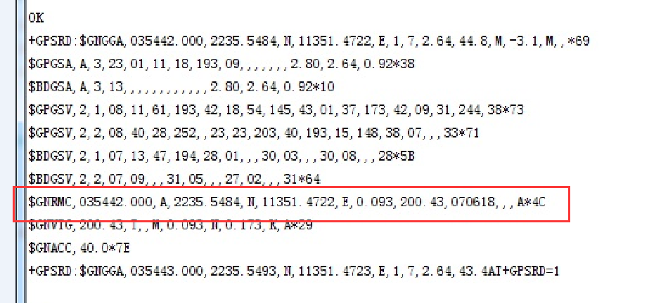
it means:
The UTC time: 035442;The valid location: A,means yes
And my location: 2235.5484, Northern Hemisphere and 11351.4722, East longitude;
and follows some charators, i do not quite understand, and care;and date: 070618(date/month/year)
-
manual soldering
05/31/2018 at 09:12 • 0 commentsonly 10 minutes for a sample soldering.... do not know why the picture rotates manually when upload to here....
will program for testing tonight...
![]()
![]()
-
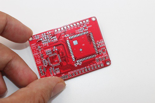
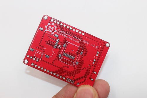
First sample Ready
05/31/2018 at 08:51 • 0 commentsPCB completed . and one sample board in manual soldering.... 10 minutes....
![]()
![]()
-
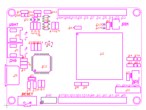
Ready for the first prototyping
05/26/2018 at 02:19 • 0 commentsthe first prototyping version, ready for production .
![]()
![]()