-
ENCLOSURES REDESIGN
10/20/2018 at 08:25 • 0 commentsThe submission date for the HackadayPrize2018 is really near and we need to prepare, gather and edit some videos. We decided was time to add some personal touch to the sensors enclosure and a small modification on the 3D files were done.
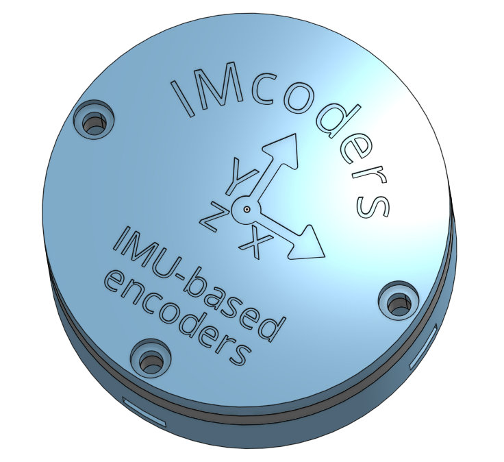
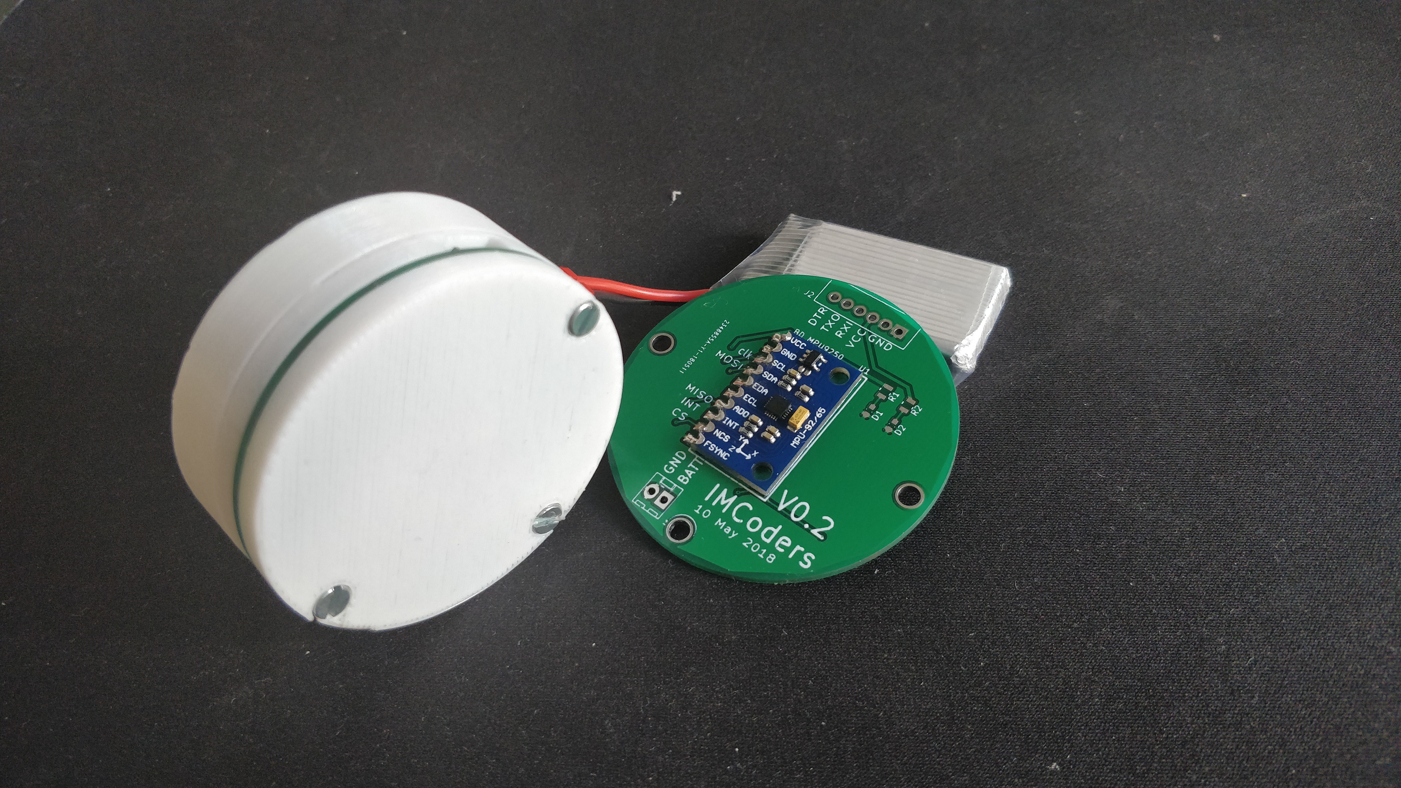
Now they have a proper name and the axis are clearly present on the outside of the box. The size of the nuts and screws are standard measurements and they fit perfectly :)
---------- more ----------![]()
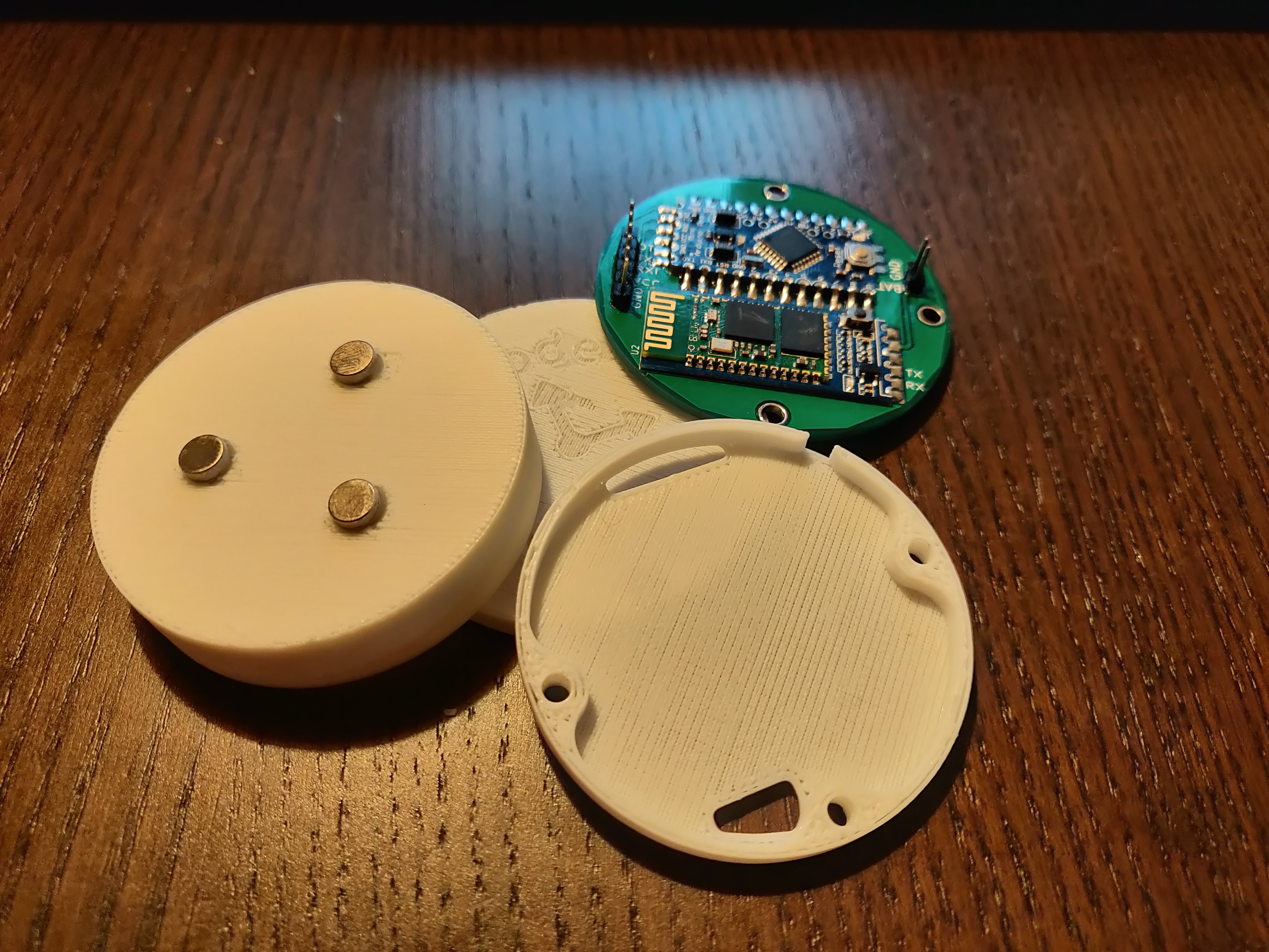
The magnets now have an exact place on the lid of the IMcoder. The nuts are hidden on the lateral surface so there are no more metallic parts on the side the sensor besides of the magnets. The screw holes are now reinforced for making the enclosure more robust. Here you can see the results:
![]()
-
SENSORS EXTRA FEATURES
10/20/2018 at 08:24 • 0 commentsThe IMcoders are working as expected, we still need to work on the stability of our Bluetooth link, but the results look promising.
Now it's time to test some extra functionalities. We will try to analyze the output of the sensors to detect if the chair is drifting or blocked.
This tests will show us if the sensors could be used to expand the functionalities of a traditional encoder or if even having three different sensors inside an IMcoders these measurements are out of the capabilities of the system, let's see!
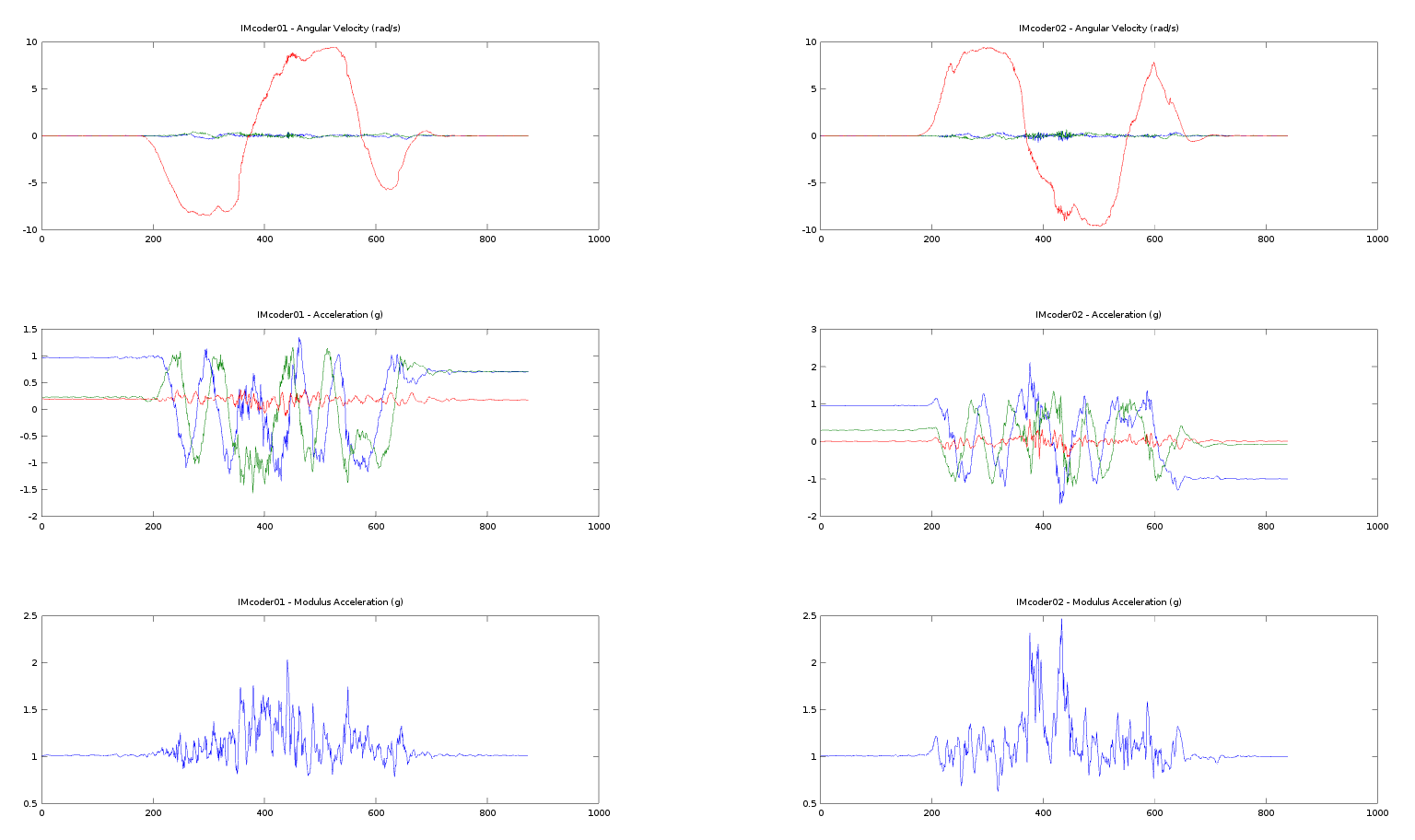
---------- more ----------In first place we will force a sudden change of direction while the Wheelchair is going forward to make the wheels to drift.
With a little bit of help from Octave we can visualize the output of the sensors while the Wheelchair is drifting. We can observe high output values from the accelerometer just when the wheel change the direction of rotation. This values match in time when the wheel is stopped and vibrating against the floor because of the drifting.
![]()
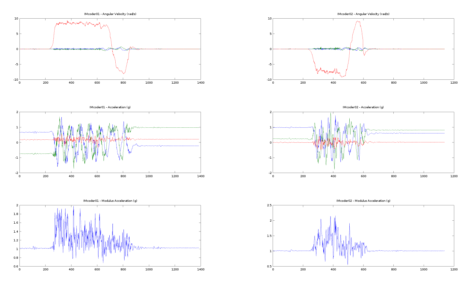
Now we completely block the chair and release it after a few seconds.
The waveform of the sensor output look quite different, we appreciate much higher acceleration values while the wheel is spinning as it is trying to push the obstacle out of its way.
![]()
Develop an algorithm able to detect this behavior in all circumstances is a big engineering effort, and unfortunately we have no more time to spend here. We see that there is a clear difference and it seems feasible to detect this two events, but further work is needed to achieve reliable results.
-
WHEELCHAIR INTEGRATION
10/20/2018 at 08:23 • 0 commentsWe are back on track!
Simulations and tests in small robots are fine, but now it is time go bigger and target our final device: an electrical wheelchair!
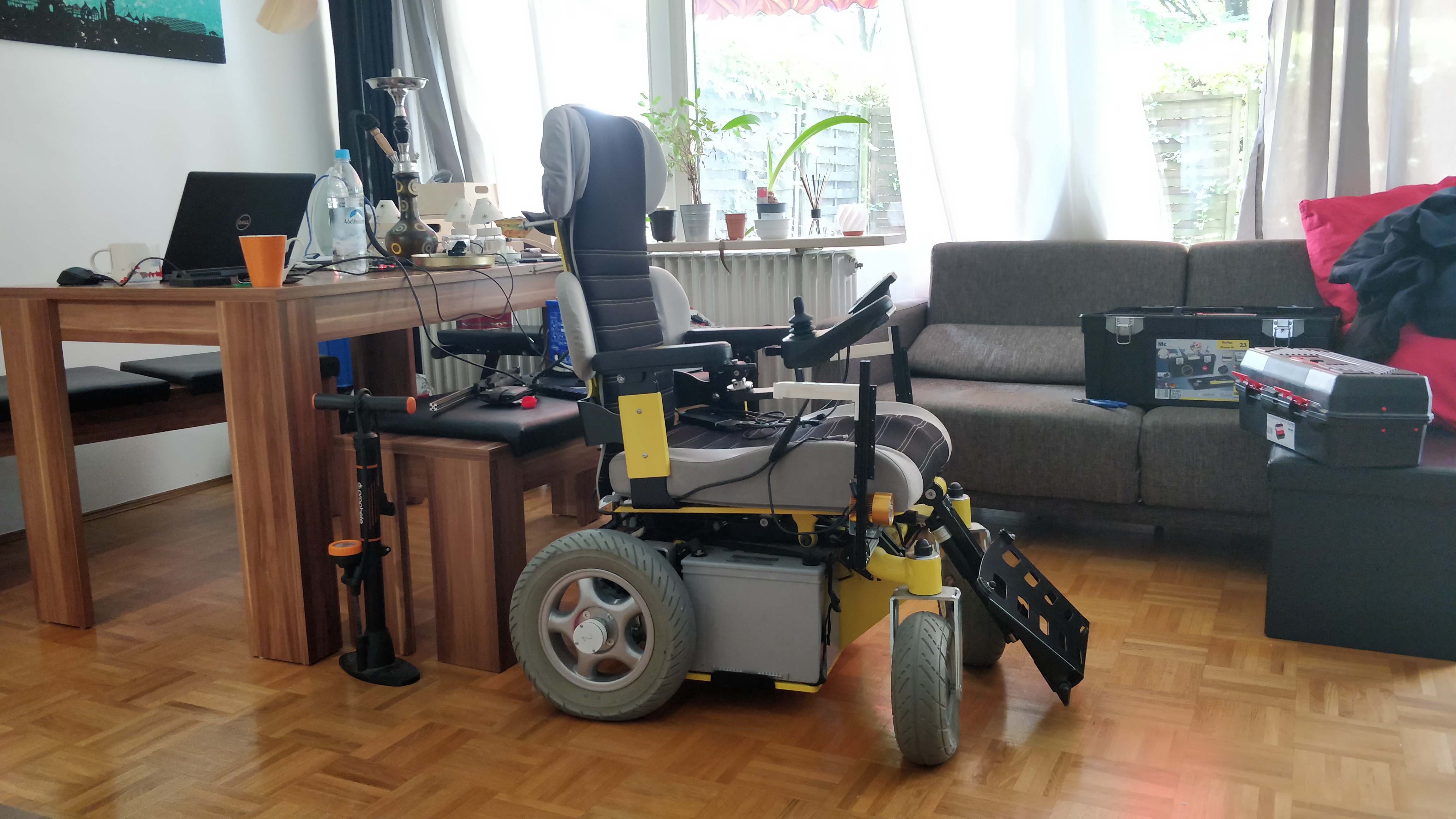
The chair was bigger than expected and it took the whole living room to set it up. To control the chair we needed some extra electronics, as the manual joystick normally used to control the device must be bypassed to directly control the chair with our software in ROS.
![]() ---------- more ----------
---------- more ----------The integration of IMcoders on the wheelchair was a matter of seconds, fortunately the shaft of the wheels were metallic and the magnets were able hold the sensor perfectly.
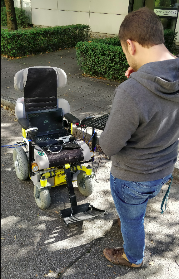
We never thought that we could have so many problems while testing the system; the bluetooth modules in the IMcorders refused to pair with our computer, the bypass module to control the devices in software was disconnecting the whole time, even the USB keyboard stopped working!
![]()
We spent about 2 hours debugging until we found the source of all the issues. Changing the IMcoders for two new ones (batteries got discharged) and a new USB HUB helped us to keep going.
Here are some videos of the outdoor testing :)
-
ROS COMMUNITY
10/20/2018 at 08:22 • 0 commentsROS Discourse
Days are going through and the project is moving forward.
Even after the success of our initial tests, it was clear that more development was needed to be done in the algorithmic part. To get some help, there is no better way than asking for it directly to the experts in the robotic field, so we made a post in ROS Discourse.
https://discourse.ros.org/t/imcoders-easy-to-install-and-cheap-odometry-sensors/5543
ROS Discourse is a platform were the ROS developers/robot makers discuss about the new trends in the robotic world as well as people expose their projects and ideas to get feedback and help from the community. And that is exactly what we needed :)
We received several ideas how to test our system. We would like to thank again all the people who contributed to the post with great ideas and constructive feedback!
ROSCon2018
After such a positive experience in ROS Discourse we decided to go bigger and move forward. Knowing this year the annual ROS conference (ROSCon) was in Madrid, it was the perfect opportunity not only to learn more about robotics and meet the community in person but also to pitch our project.
With our goals clear we decided to flight there and show our project! And here are the results :)
If you are interested in the slides of the presentation you can download them from here:
https://roscon.ros.org/2018/presentations/ROSCon2018_Lightning2_2.pdf
See you soon!
-
REAL ROBOT ODOMETRY
10/20/2018 at 08:22 • 0 commentsNow that the sensors are mounted on a real robot we can get some measurements and check if the data is useful.
Thanks to the previous software work and the integration in ROS testing the sensors with a real robot is pretty straightforward. Changing the wheel_radius and wheel_separation parameters in the file to launch the differential odometry computation software is all we need. Adapt the system to different platforms is fast and easy :)
After checking that everything was up and running we were ready to record some datasets to work with the data offline. We made some tests and here you can see the result.
Linear trajectory
![]()
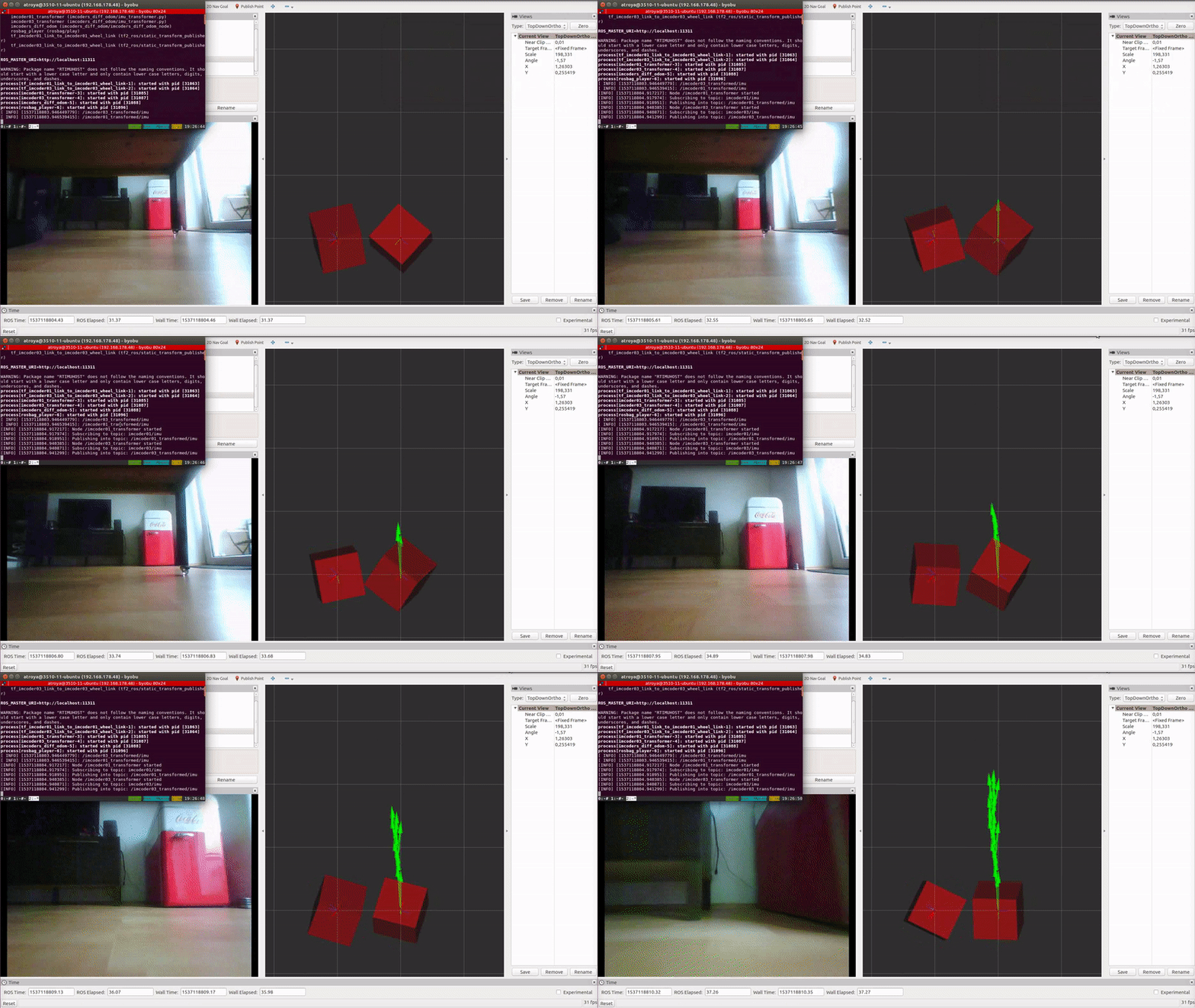
As it can be seen in the left side of the upper animation, the displayed image is the recorded video with the robot camera, the red boxes are the output of the IMcoders (one per wheel) and the green arrows are the computed odometry from the algorithm we developed (btw, thanks to Victor and Stefan for the help with it!).
Here it is the same dataset but this time displaying just the computed path followed by the robot (red line):
Left turn trajectory
Complex trajectory
In this video you can see an additional yellow line which is also displaying the path followed by the robot but with a different filter processing the output of the IMcoders. Probably you noticed that the trajectories are slightly different. This is because several algorithms can be used to compute the pose of the robot wheel.
Due to the time constraints we had no time to prepare a proper verification environment so we cannot ensure which one is better.
Conclusions
Finally, we can conclude that much more time shall be invested in the research of algorithms for computing the estimated orientation of the wheel due to the important role that they play when computing an odometry out of it.
-
REAL ROBOT INTEGRATION
10/20/2018 at 08:20 • 0 commentsNow that we have demonstrated in the simulation that it is possible to compute an odometry using the simulated version of the IMcoders, it is time to make some tests with a real robot.
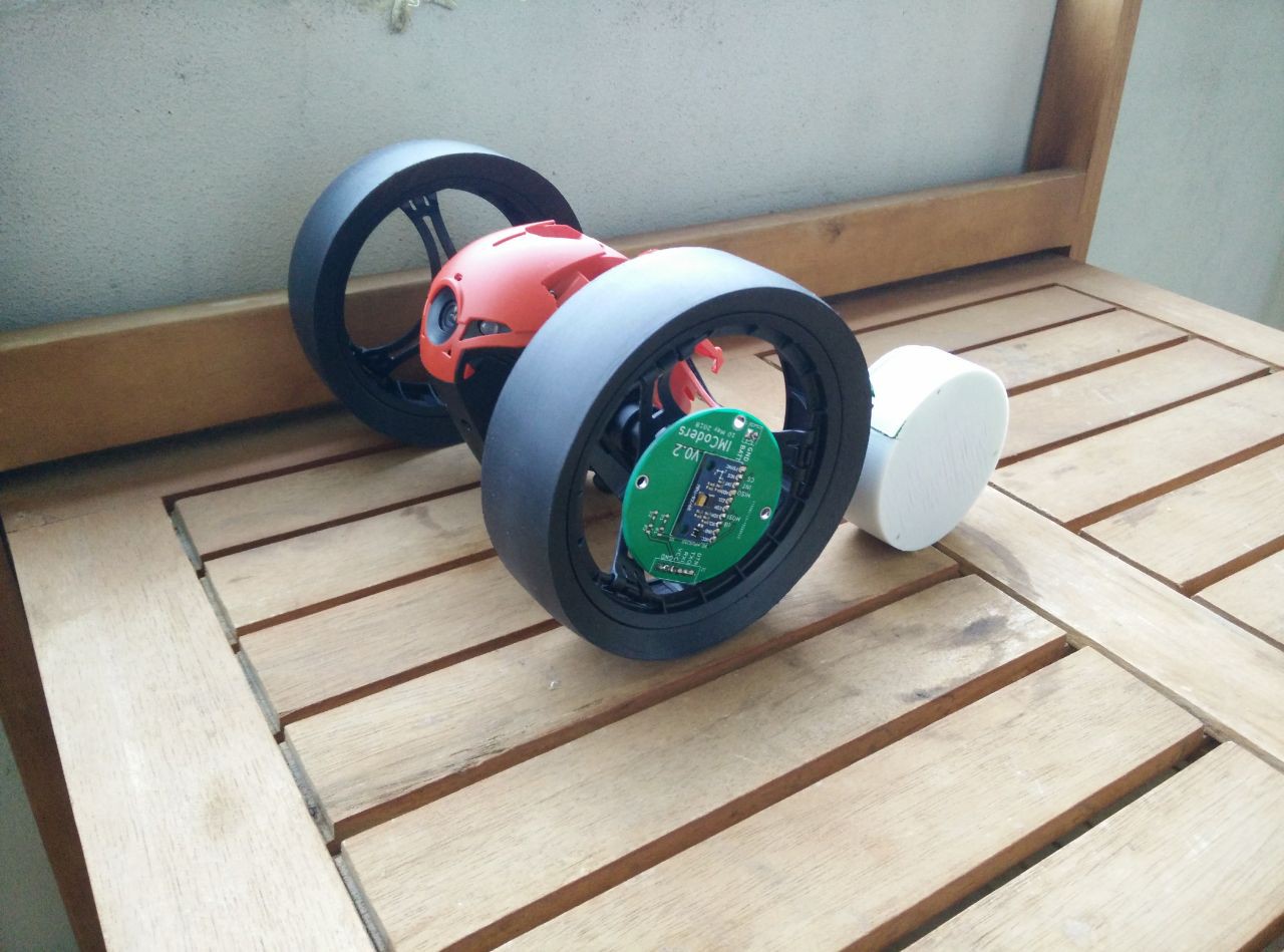
In order to do that we need a robot. After looking some of them, we finally decided to use a commercial one, the Jumping Race MAX from Parrot. It has an open API , this API will ease the testing and algorithm verification as we don't have to modify the hardware to control it.
Here it is next to the IMcoders:
![]()
We thought it had metal rims so we could attach the sensors with magnets. Unfortunately, they are made of plastic. No worries, a 3D printer is making our lives easier.
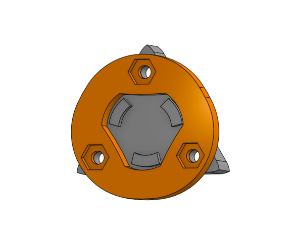
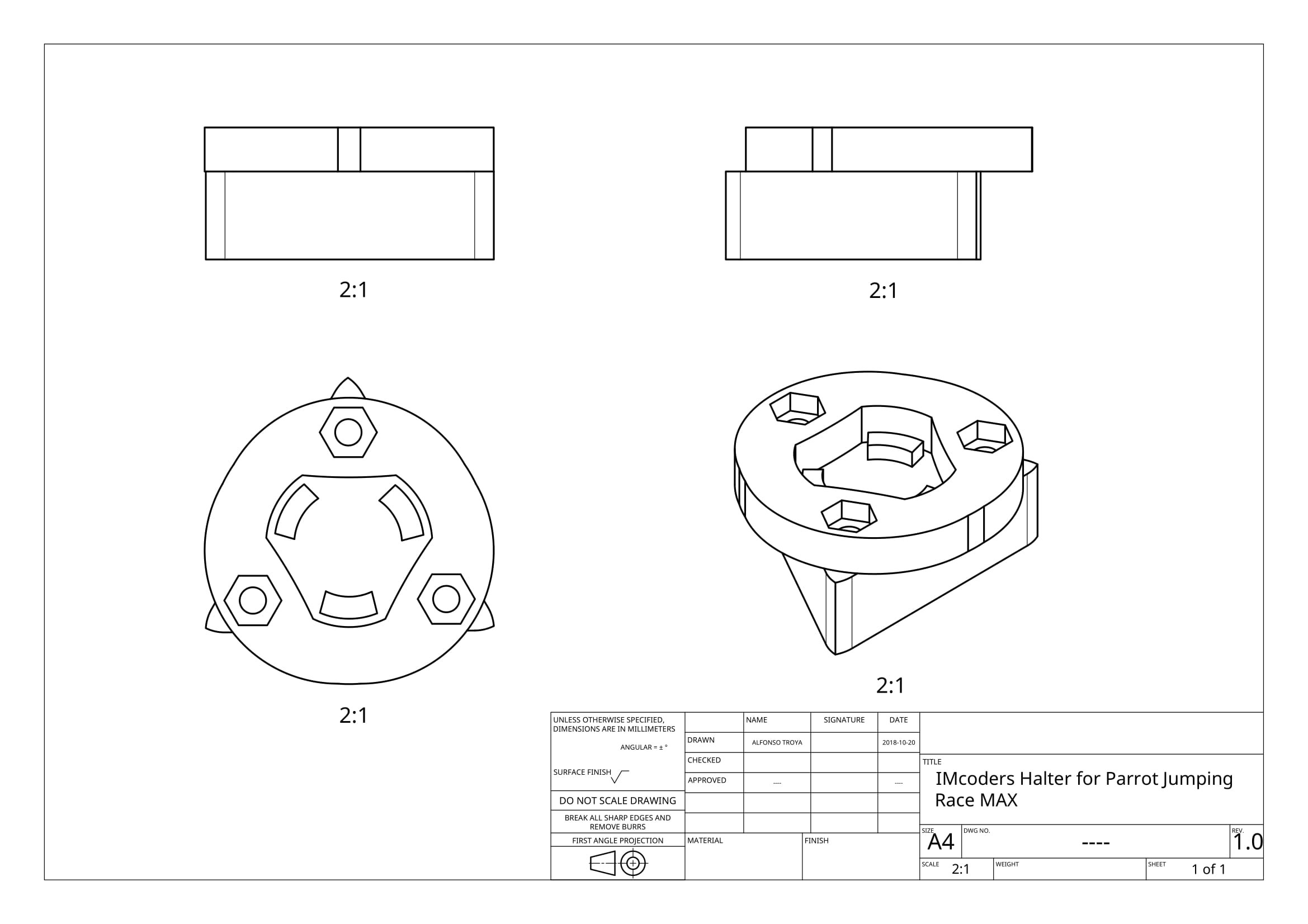
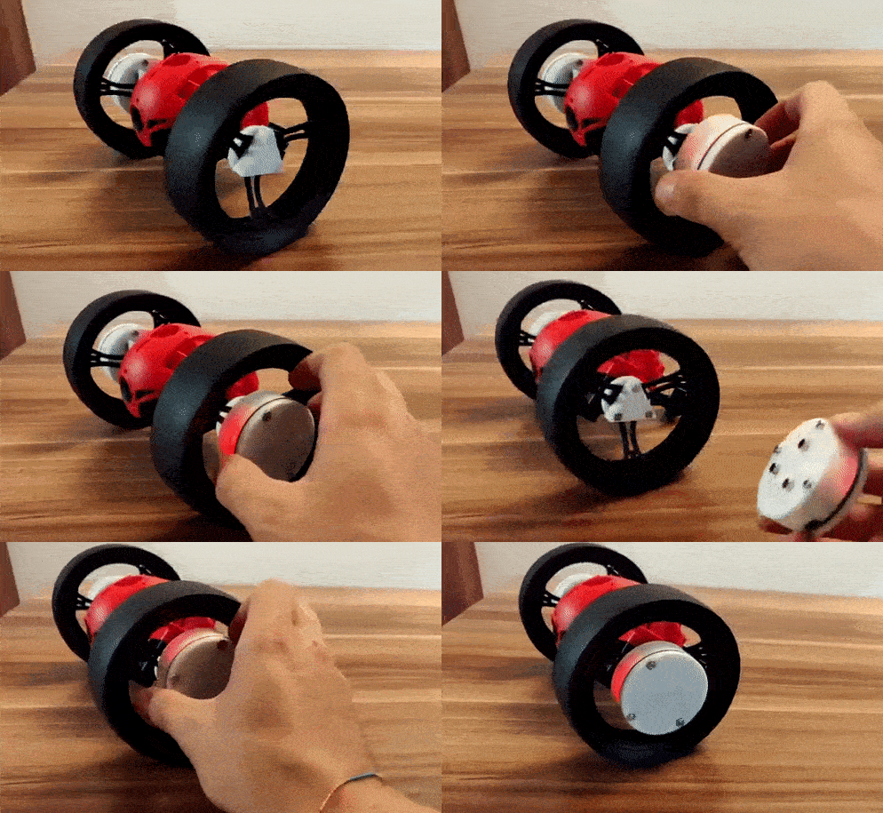
After a couple of hours for designing and printing, we have our attaching system which allows us to attach an detach the IMcoders really easy.
![]()
![]()
Some hours later, after waiting for the 3D printer finish, we have holders for our sensors!.
Here you can see the result:
![]()
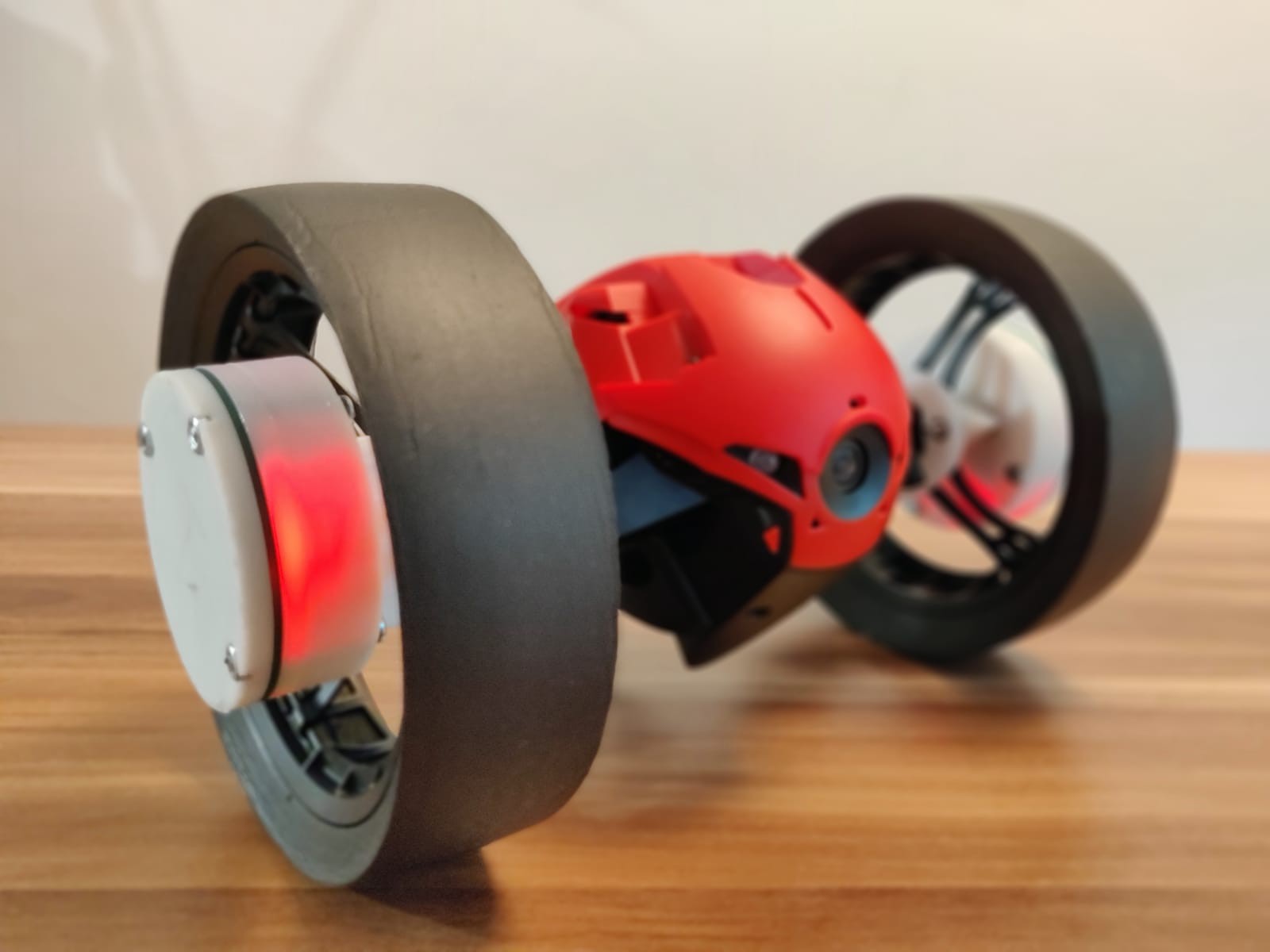
Not bad, eh? As you can see, the mechanism to attach and detach the module is working pretty good. This is the final looking of the robot with IMcoders:
![]()
The robot has a differential steering and so has the simulated robot we developed the algorithm for. We just have to modify some parameters in our simulation model to match the real robot and our sensors will be ready to provide odometry.
-
ROBOT ODOMETRY
05/31/2018 at 00:24 • 0 commentsHi again!
We have some very good news, our Robot is moving!
The simulation environment is up and running. The calculations for the odometry and hardware integrations are done! There is still a lot to be developed, tested and integrated but we can say the first development milestone is complete and the Alfa version of the IMcoders closed.
![]() ---------- more ----------
---------- more ----------DIFFERENTIAL DRIVE
To explain what is happening on the simulations we need first to explain with what kind of Robot we are dealing with. As this are the first tests we decided to keep it simple and go with a robot with differential drive. Don't you know what that means? No problem, here we have a small overview (information extracted from Wikipedia).
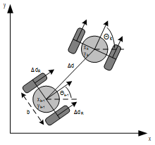
A differential wheeled robot is a mobile robot whose movement is based on two separately driven wheels placed on either side of the robot body. It can thus change its direction by varying the relative rate of rotation of its wheels and hence does not require an additional steering motion. If both the wheels are driven in the same direction and speed, the robot will go in a straight line. If both wheels are turned with equal speed in opposite directions, as is clear from the diagram shown, the robot will rotate about the central point of the axis. Otherwise, depending on the speed of rotation and its direction, the center of rotation may fall anywhere on the line defined by the two contact points of the tires.
![]()
ODOMETRY
Up this point everything is clear, isn't it? We have a robot with two wheels and based on the speed of them, the robot will change its direction and speed. The theory is clear, but... how can we calculate the movements of the robot?
To keep this entry short we are going to look at the calculations from a conceptual point of view, not going into detail in each step. We are planning an entry where all the concepts and maths involved in the calculations (Quaternions, rotations, sampling rate, etc..) will be covered in detail. Right now we need to finish all the things before the deadline for the [ROBOTICS MODULE CHALLENGE].
If you can't wait you can have a look at the code in our GIT repository, the maths and everything are there. Feel free to modify them and play around!
Odometry for differential drive robots is a really common topic and several algorithms to solve this problem can be easily found in the Internet (that is one of the reasons we decided to start with this kind of driving mechanisms). To perform these calculations, independently of the algorithm used, the calculation of the linear speed of the wheels are involve and that is exactly what we are going to do. Let's compare the calculations done when using traditional encoders and the needed ones with IMcoders to understand why the system works.
Traditional Encoders:
Traditional encoders are able to count "ticks" while the wheel is spinning, each "tick" is just a fraction of a rotation. Lets assume we have a robot with two wheels with 1 meter diameter each and one encoder in each wheel with 360 ticks per revolution (one rotation of one wheel clockwise implies a count of 360 ticks, and counterclockwise -360 ticks)
To calculate the linear velocity of one wheel we will ask the encoder its actual tick count. Lets assume the enconder answers with the tickcount 300. After 1 second we ask again and now the answer is 390. With this information we can now calculate the linear velocity of the wheel.
We know that in an arbitrary time (lets name it "t0") the tick count was 300 and one second later (lets call this time "t1") it was 390. Knowing that our encoder would count 360 ticks per revolution, an increase of 90 ticks implies a rotation of 90º. As duration between the two measurement is 1 second, we can easily calculate the linear speed of the wheel:
![]()
If we repeat the same procedure with the other wheel we can also calculate the linear velocity of the second wheel and use this information as input values for any already available differential drive odometry algorithm.
IMcoders:
With the IMcoders sensors the procedure is really similar, but the starting point is a little bit different. As you probably remember from our entry blog [REAL TESTS WITH SENSORS] the output of the sensor is the absolute orientation of the IMcoder in the space. That means that we can ask our sensor where is it facing in each moment.
To calculate the linear velocity of one wheel we will ask the IMcoder its actual orientation. Lets assume the sensor answers saying it is facing upwards (pointing to the sky +90º). After 1 second we ask again and now the answer is that it is facing forward (0º). With this information we can now calculate the linear velocity of the wheel.
We know in an arbitrary time (to keep the same naming lets name it also "t0") the initial orientation was 90º (sensor facing to the sky) and one second later (in time "t1") it was 0º (facing forward), clearly that is a 90º rotation in the orientation. As between the two measurement we waited 1 second, we can easily calculate the linear speed of the wheel.
![]()
If we repeat the same procedure with the other wheel we can also calculate the linear velocity of the second wheel and use this information as input values for any already available differential drive odometry algorithm.
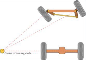
IMPORTANT: the output of the IMcoders sensor is the absolute orientation of the wheel in the space (3 axis; X, Y and Z), for all this calculations we are assuming the wheel is only spinning around one axis (which is the normal case for a robot with differential drive) but this is not the case for robots with ackerman steering, where this tridimensional orientation can be really helpful as the wheel change its position in two diferent axis:
![]()
SIMULATION
Ok, ok, theory is good and it "should" work, but... does it really work? Of course!
To understand what is really happening in the simulation let's split the system to explain what are we looking at. The system works as follow:
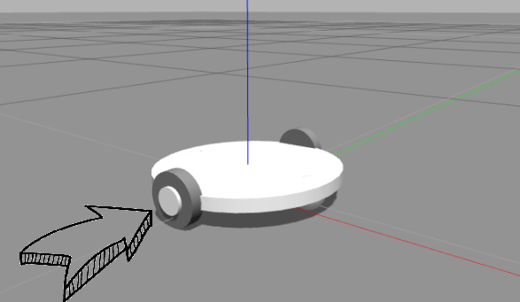
- Movement commands are being sent to a robot model in a simulation environment (Gazebo) where two of our IMcoders are attached to the wheels of the robot model (one per wheel).
![]()
- When the robot moves, the attached IMcoders sent the actual orientation of the wheels to our processing node.
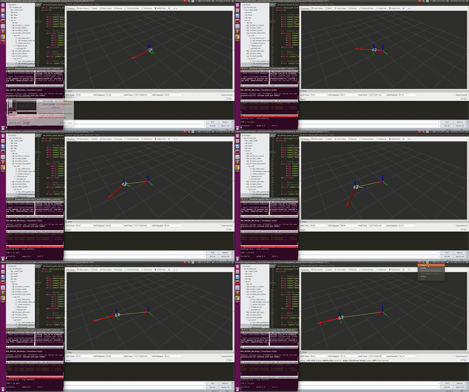
- The node outputs odometry message (red arrow) and a transformation to another robot model which we display in a visualization tool called rviz.
- The robot moves based on this odometry information!
![]()
Now that our simulation environment is working we can characterize our system, there are several questions still open this simulation model will help us to solve.
- How fast can a wheel spin and be measure by our IMcoders?
- How many bits do we need in the Accelerometer/Gyros in the IMcoders to produce a reliable odometry?
- Which algorithm performs better in different scenarios?
- etc...
-
REAL TESTS WITH SENSORS
05/30/2018 at 23:24 • 0 commentsIn the previous log we checked that we are able to simulate the IMcoders for getting an ideal output (we will need it for making the algorithm development much easier and for verifying the output of the hardware).
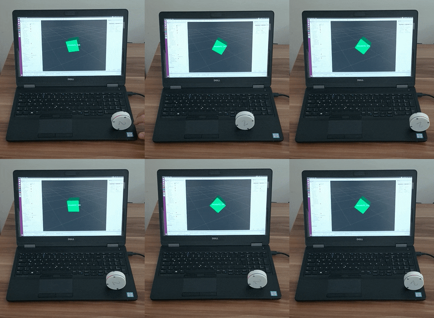
Let's check in Rviz (ROS visualizer) that the movement of our sensors corresponds with the data they output. The procedure is quite easy (pssst! It is also described in the github repo in case you already have one IMcoder).
Then, we activate the link with the computer, start reading the sensor output, opening the visualizer and...
![]()
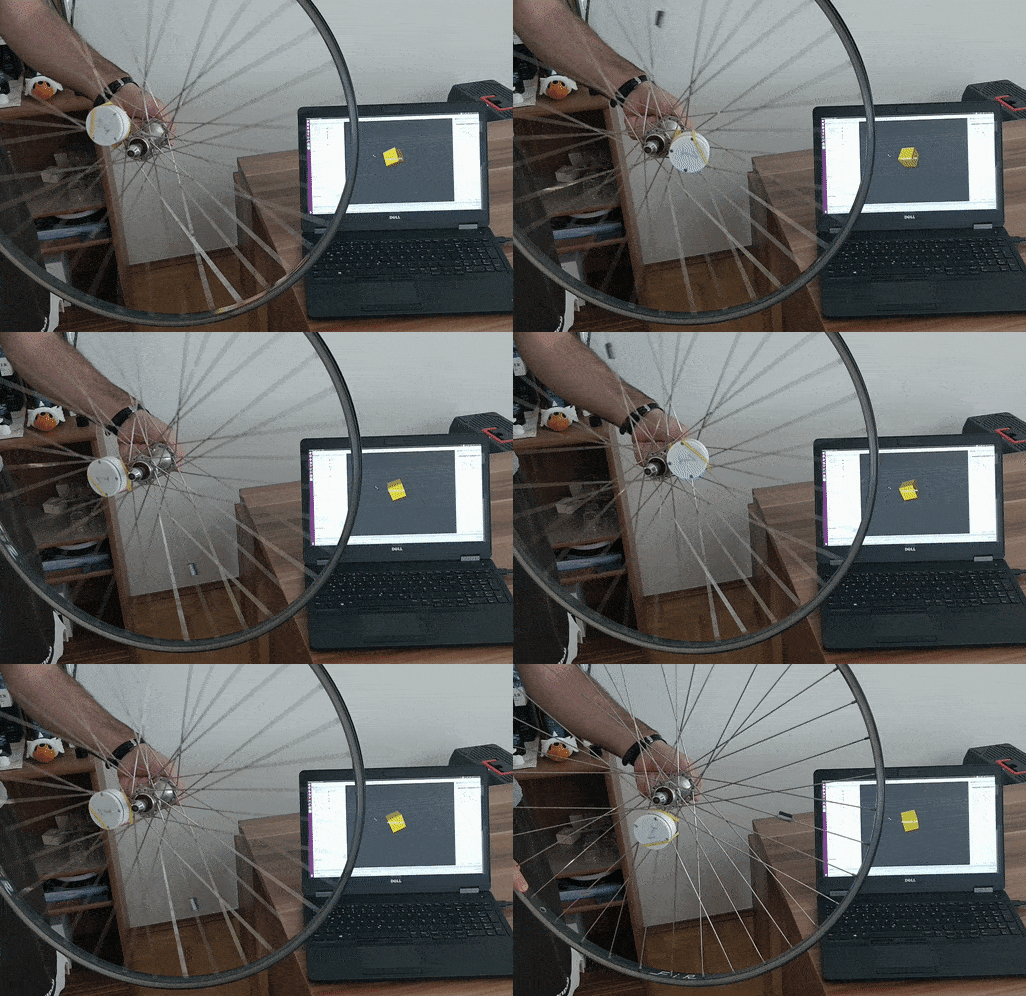
Voilà! The visualization looks great. Now we are ready to check the sensor in a real wheel. Let's start with that broken bike there...
---------- more ----------![]()
It doesn't look bad at all. There is some not desired rotation in one axis but the sensors are not calibrated so the result is quite satisfactory.
Ok, so we tried just with one sensor, but why not using all of them?
After wondering why one of the IMcoders had a bit of delay, we found out that the bluetooth driver we are using in the computer for the test is not fully supported so it is not very stable. We tried out with other computers days after and there was no problem at all.
-
SIMULATION IS IMPORTANT TOO
05/30/2018 at 22:52 • 0 commentsOk, so now the hardware is working and we have a lot to do, but in order to have a reference for comparing the output of the real sensors, we want to simulate them for getting the ideal output. In order to ease the use of the sensors and making the rest of the people to use it, we created a github repository where you can find all the instructions for running the simulation with the sensors (and with the real hardware too!). As we want to integrate them in ROS, it makes sense to also use for integrating all the simulation. Probably most of you already now it if you already worked with robots, but for those who don't here you can find an introduction to it. So let's begin!
Our first approximation: a simple cube
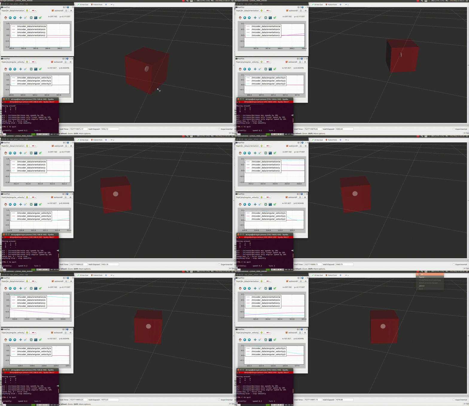
As our sensors are providing an absolute orientation, the easiest way to see the rotation, is using a simple cube. Inside of it, one of ours sensors is inside, so we are able to move the cube in the simulated world and see the output of our sensor:
![]()
Let's tell the cube to move and let's see what happens...
---------- more ----------![]()
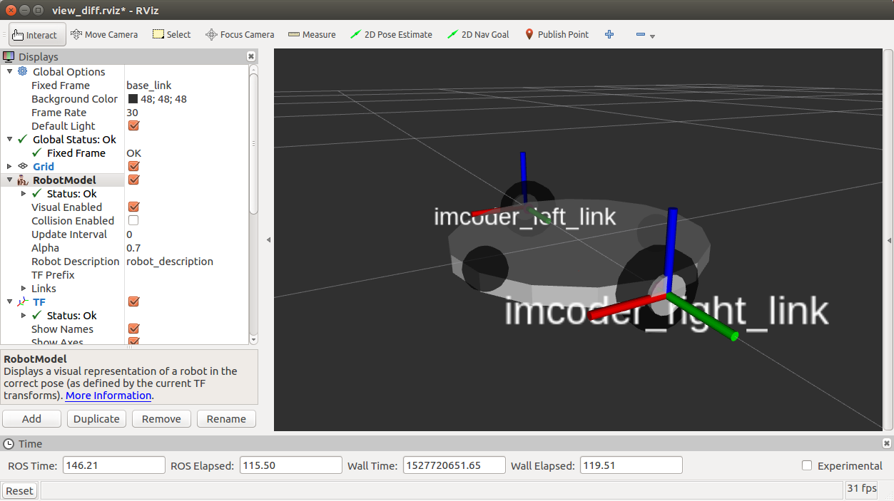
It is moving! So we can check the now the output of the IMcoder (can you see it there just in the middle of the cube?). And the output of the IMcoder looks fine too. There you can see the plot for the orientation of the sensor and also for the angular velocity. Now we can go one step further and integrate some IMcoders in a simulated robot:
![]()
For not struggling our minds, we took an already designed robot and we attached our sensors to it. Now we are prepared for trying to get an odometry out of there...
-
3D CASE DESIGN
05/26/2018 at 16:18 • 0 commentsBETTER WITH ENCLOSURE
The days pass quickly and the project is moving forward. Before the development on the algorithmic part is finished we are working on an enclosure we can attach to our tests platforms.
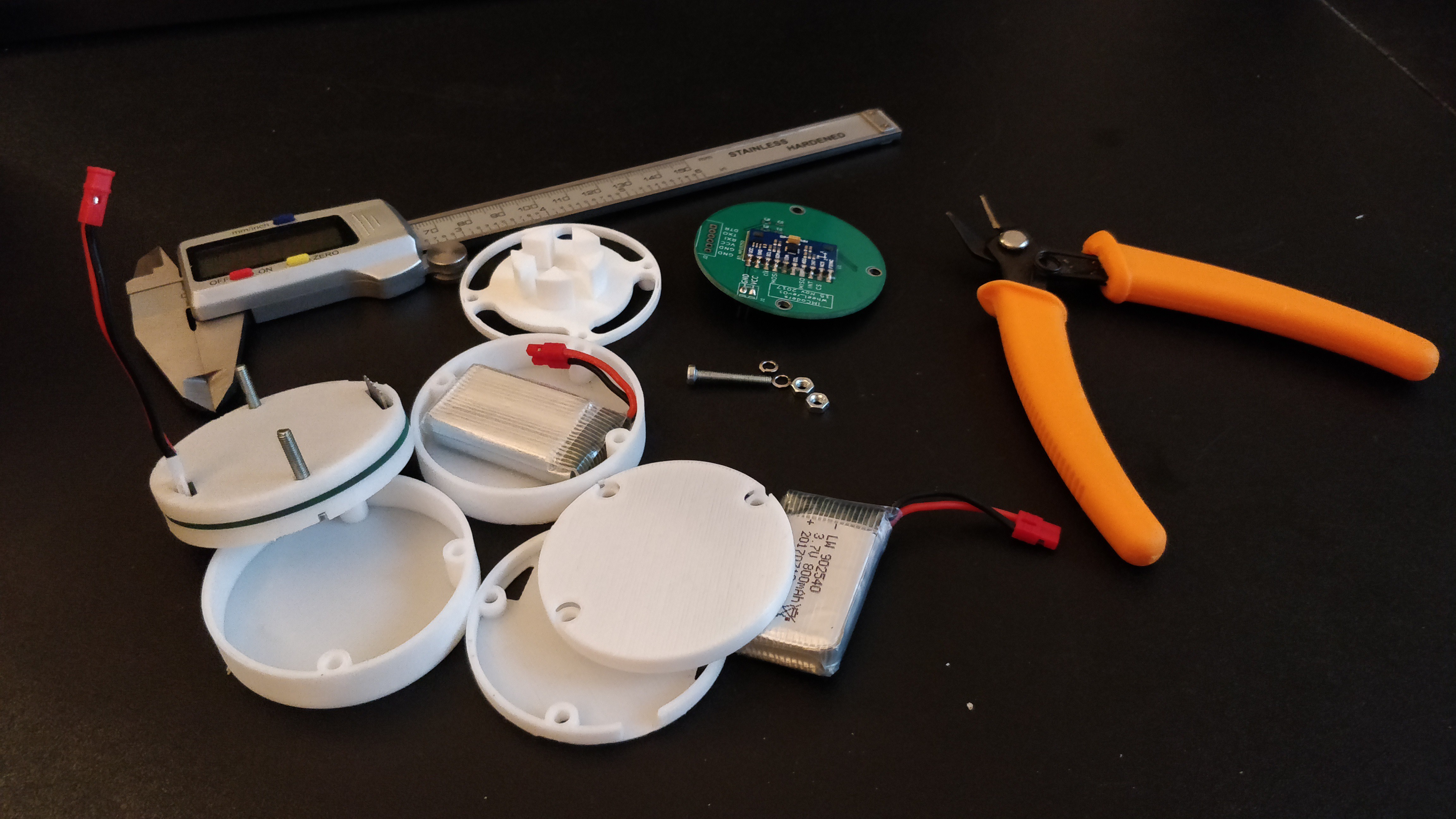
A case is not only an attachment help for the final device, it will also help us to use the sensor without fear of shorting something out or breaking a connector. The design is extremely simple, two plastic covers with the PCB in the middle. An extra piece will hold the battery in place.
![]()
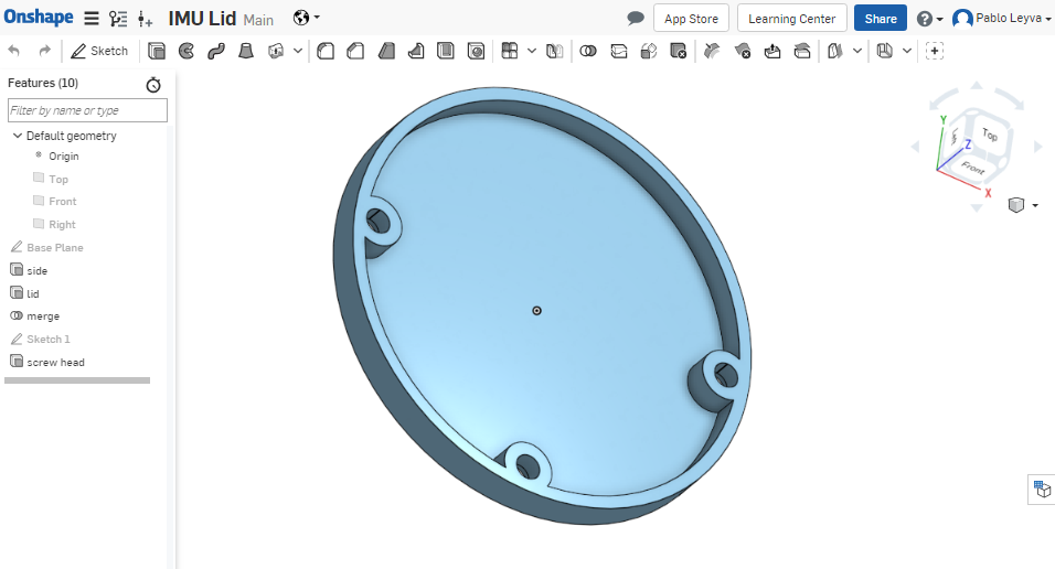
The design was done on Onshape and is already available. We are planning to improve the case and get rid off the screws, but will work on that once everything is up and running. Right now we have other priorities to focus on.
---------- more ----------As you can see the design of one of the lids is extreamly easy, lets print them!
The pieces need almos no post-processing after comming out of the 3D printer.
![]()
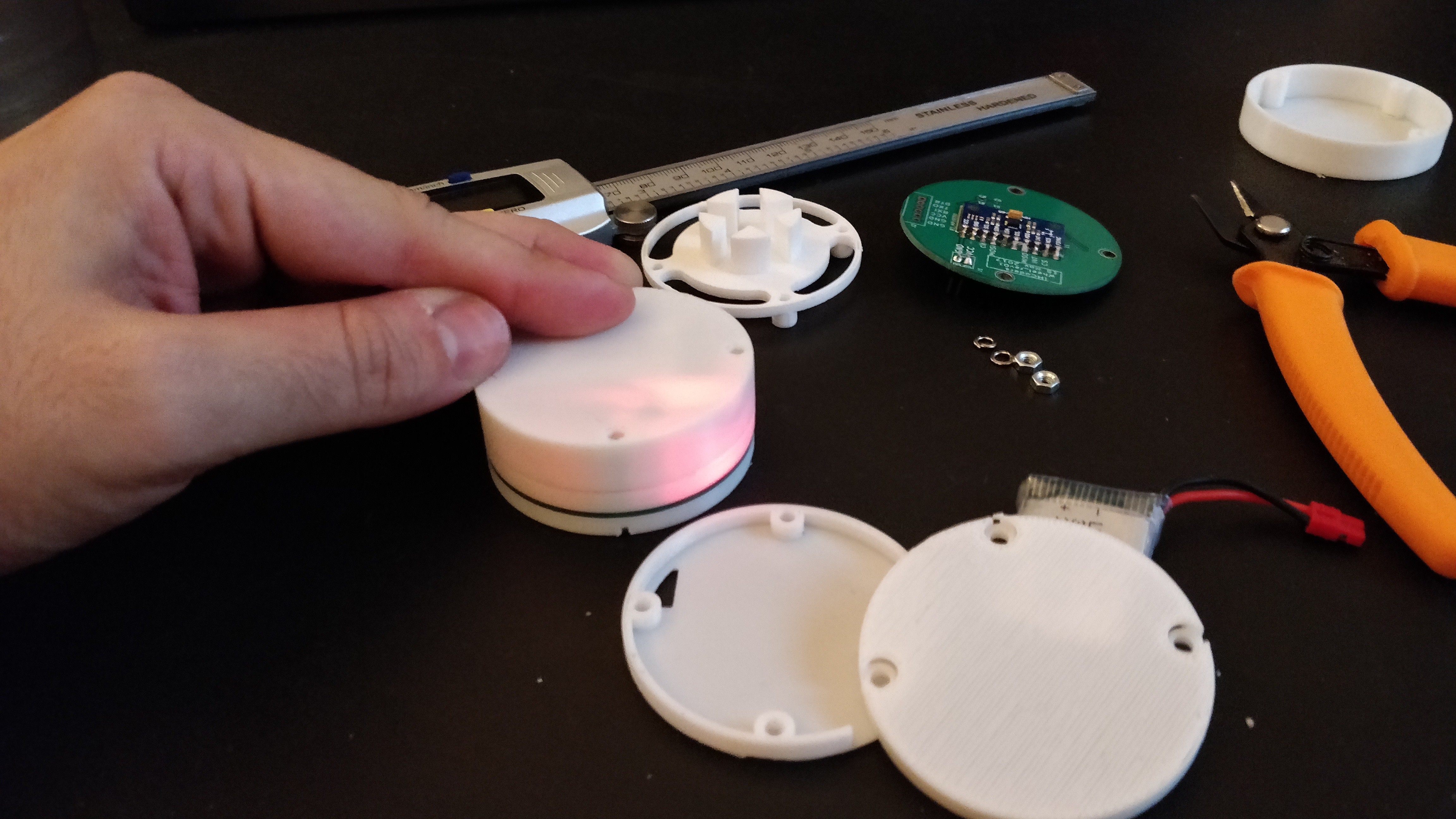
And they still work!
![]()
IMcoders
IMU-based encoders. IMcoders provides odometry data to robots with a minimal integration effort, easing prototyping on almost any system.
 Pablo Leyva