-
Preparation for SuperCon!
10/28/2018 at 01:09 • 0 commentsMy pilgrimage to Pasadena for superCon is now synonymous with the beginning of Fall. I start enjoying the crisp chill in the air at night, eat a lot of sweet candy, have a couple weeks where I'm busier than sense... and then, BAM! I'm in the car with a bountiful harvest of whatever nonsense I've been concocting to show to my friends and fellow hackers.
It's my favorite *con* or *festival* or *gathering*- I enjoy being with my people, and seeing all the inspiring work that's been unfolding in the now.
This hacker harvest fest (I'm going to call it that) is fun, but it also brings a fair amount of stress in the week or so leading up to it. That's where I find myself right now.
My intention is to bring the whole SHE BON project along with me to demo and share during the three days of festivities. I won't be wearing all the augments at once- but I will wear them all at some point throughout the con, so this means they all need to be *wearable* and mobile, - they must all have power supplied to them! somehow.
My biggest hurdle this weekend is wrapping up some obvious (potentially critical) odds and ends. primarily, how my 3D printed assemblies will in fact mount to the fleshy surface of my body - amazingly, I didn't think this far for some items, like the salmon "panties". (this also comes with decisions about what I'm going to wear underneath them).
THE BIG TODO
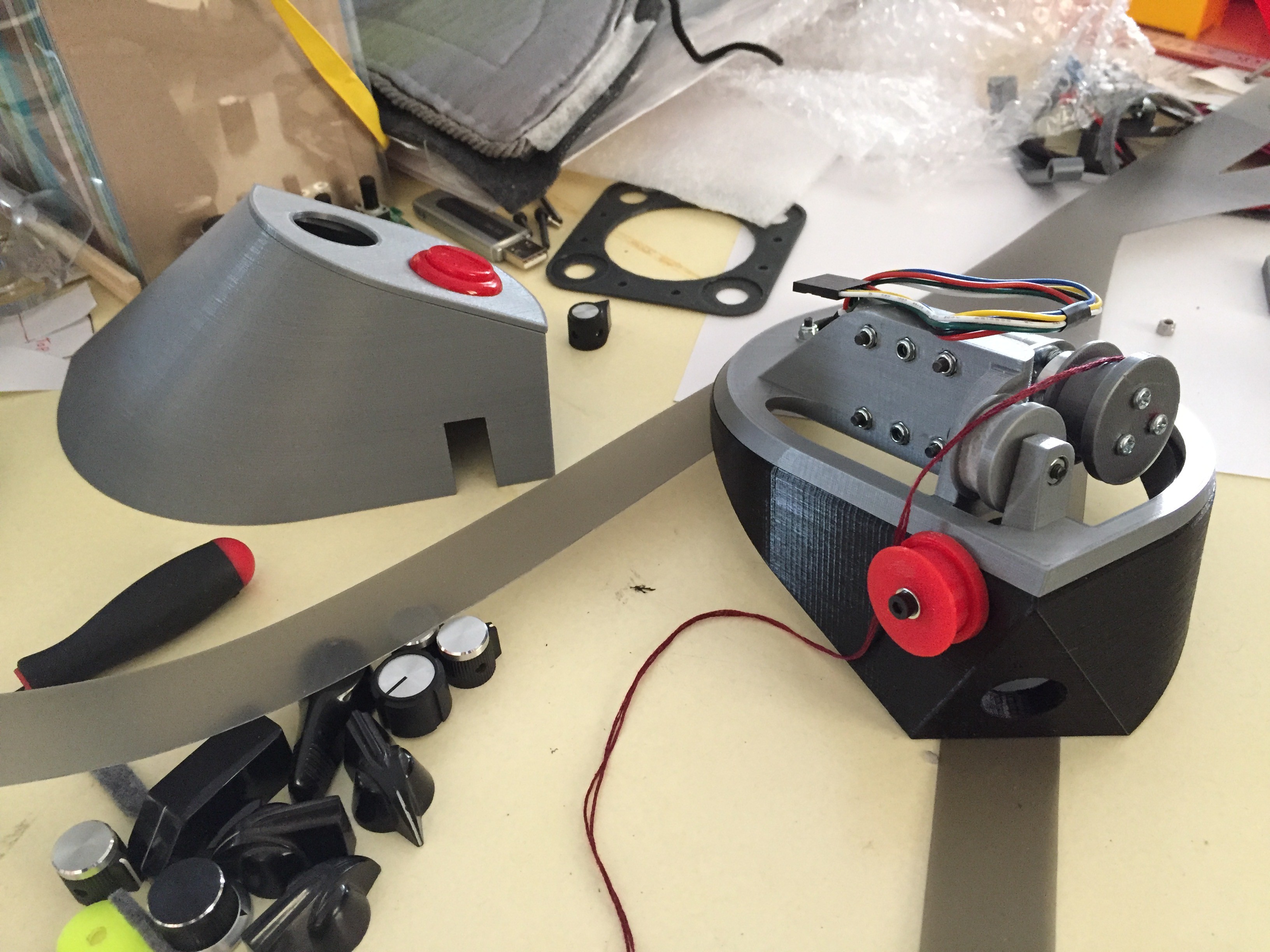
- mount and manage PCBs and wire harness of winch belt
- better belt buckle for winch belt
- run power to winch belt from pulse pack
- install core power supply to pulse pack + voltage regulator step down for sub systems
- tighten up pulse pack cat5 ports >.<
- arm brace for popgirl
- instal voltage regulator for winch belt
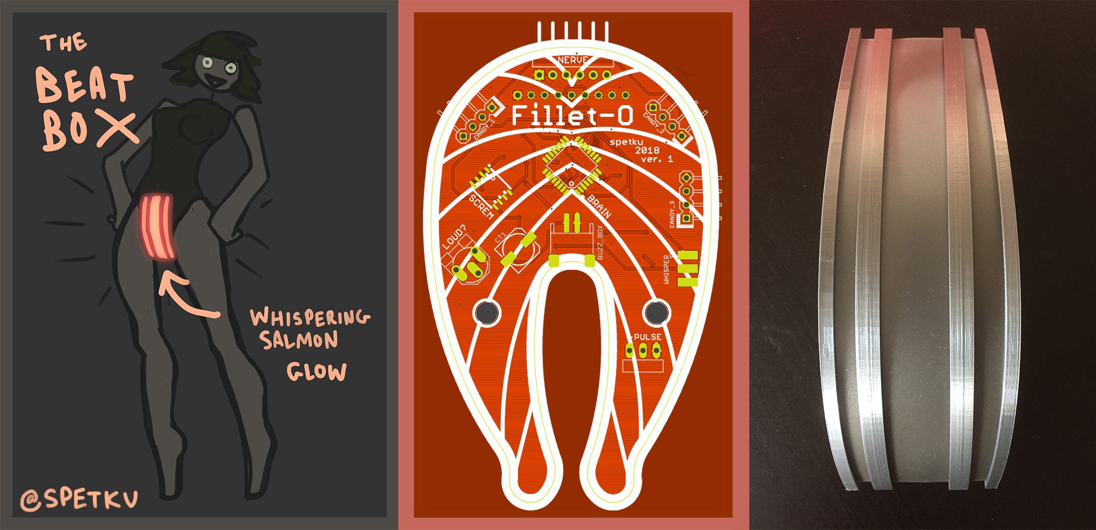
- make beatbox wearable!
- tweak salmon code for heat monitor
- power the salmon
- fit the fillet-o board into the new salmon
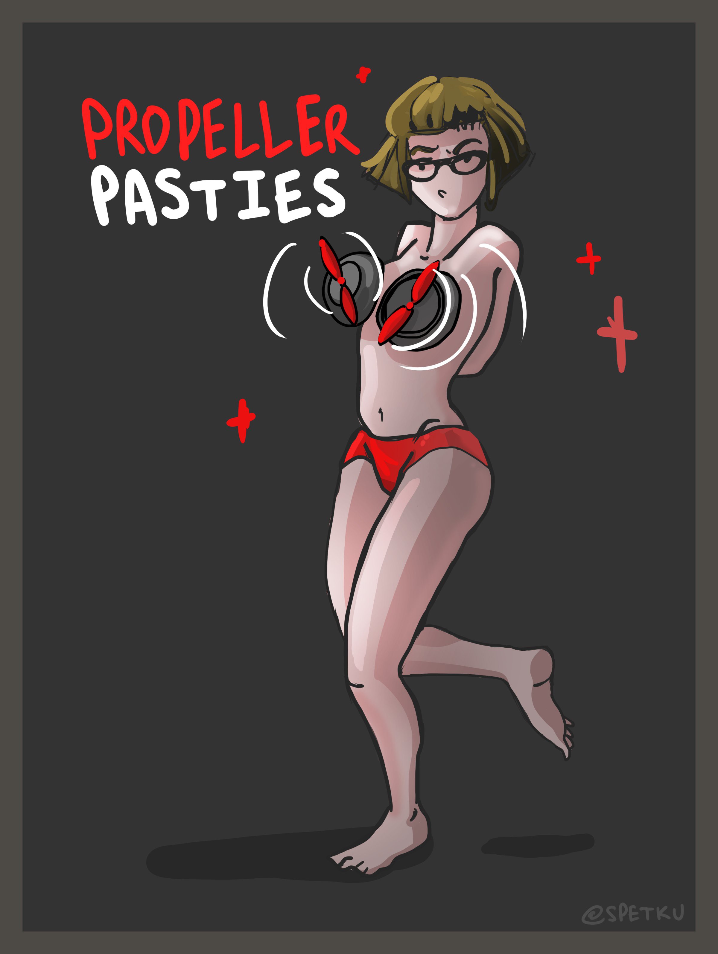
- rebuilt circuit for propeller pasties
- make a bra attachment for pasties
- also need to run power to pasties
Any how. The layout of the SHE BON main site has been updated again to reflect all the new additions to the suit.
![]()
Enjoy the concept art and stuff! I'll see you at superCon!! <3
-
AS OF NOW
10/22/2018 at 01:58 • 0 comments![]()
The Hackaday Prize Finals are nearly upon us. I've pushed a lot of information into the ether in the past few weeks, so I figured it wouldn't be a bad idea to post a summary of all that I've created up until now.
As it stands- I have produced the first iteration of the core platform: the PULSE. This includes the core brain and user interface, which are open source, fully documented on this page, and ready for you to replicate or fork for your own devious schemes.
THE SHEBON PLATFORM
documented in detail for your use:
THE PULSE (PRIMARY BRAIN)
THE POP GIRL (USER INTERFACE)
- the software for the POPgirl user interface
- the snazzy arm-mounted enclosure for the POPgirl interface
THE WEARABLE AUGMENTS
created for my personal use, but I hope they inspire
I've built a device to satisfy five of the nine augments I proposed creating for this series of wearables (YAY!)
- The Propellor Pasties
- The Beat Box
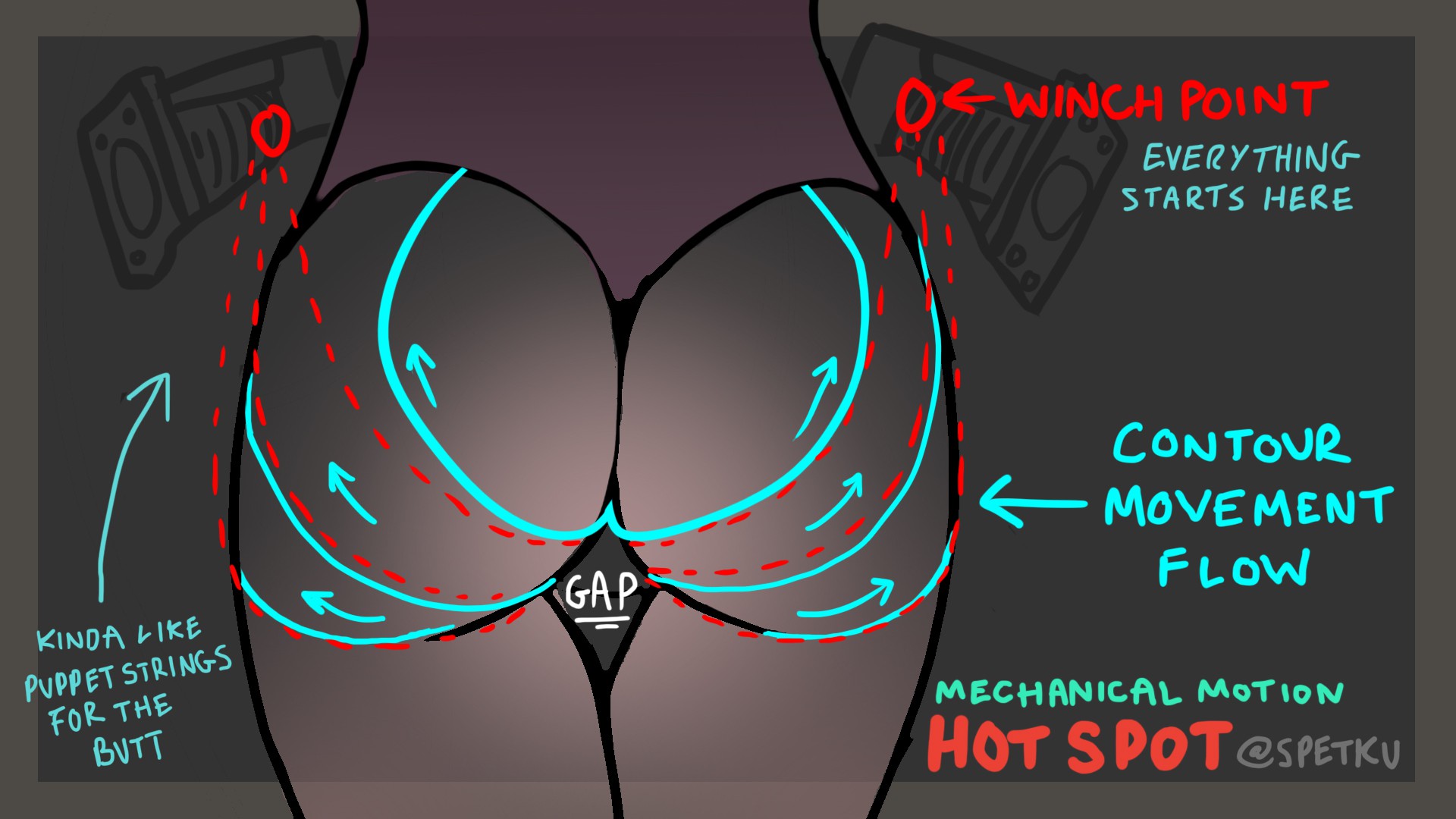
- The Hot Spot
- The Spank Skirt (in the works)
---------- more ----------Project Videos, Concept Art, and Photos...
Since this is a check point- enjoy the assets I've created to document and promote this project so far! :)
CONCEPT ART
all hand drawn by me to help plan the look of my designed objects!
pulse pack:
![]()
![]()
beat box:
![]()
![]()
![]()
hot spot:
![]()
![]()
![]()
![]()
pop girl:
![]()
![]()
![]()
PHOTOS
enjoy some of my favorite pictures from the augment build logs!
pulse pack
![]()
...
![]()
...
![]()
...
![]()
hot spot
![]()
...
![]()
...
![]()
...
...
![]()
...
![]()
best stickers ever
pop girl
![]()
...
![]()
core system
![]()
beat box
...
...
![]()
...
![]()
...
propellor pasties
...
...
...
...
![]()
PROJECT VIDEOS
here are the produced project updates for each of the systems I've developed for SHE BON!
...and this is only the beginning... <3
-
The PULSE PCB
10/21/2018 at 20:59 • 3 comments![]()
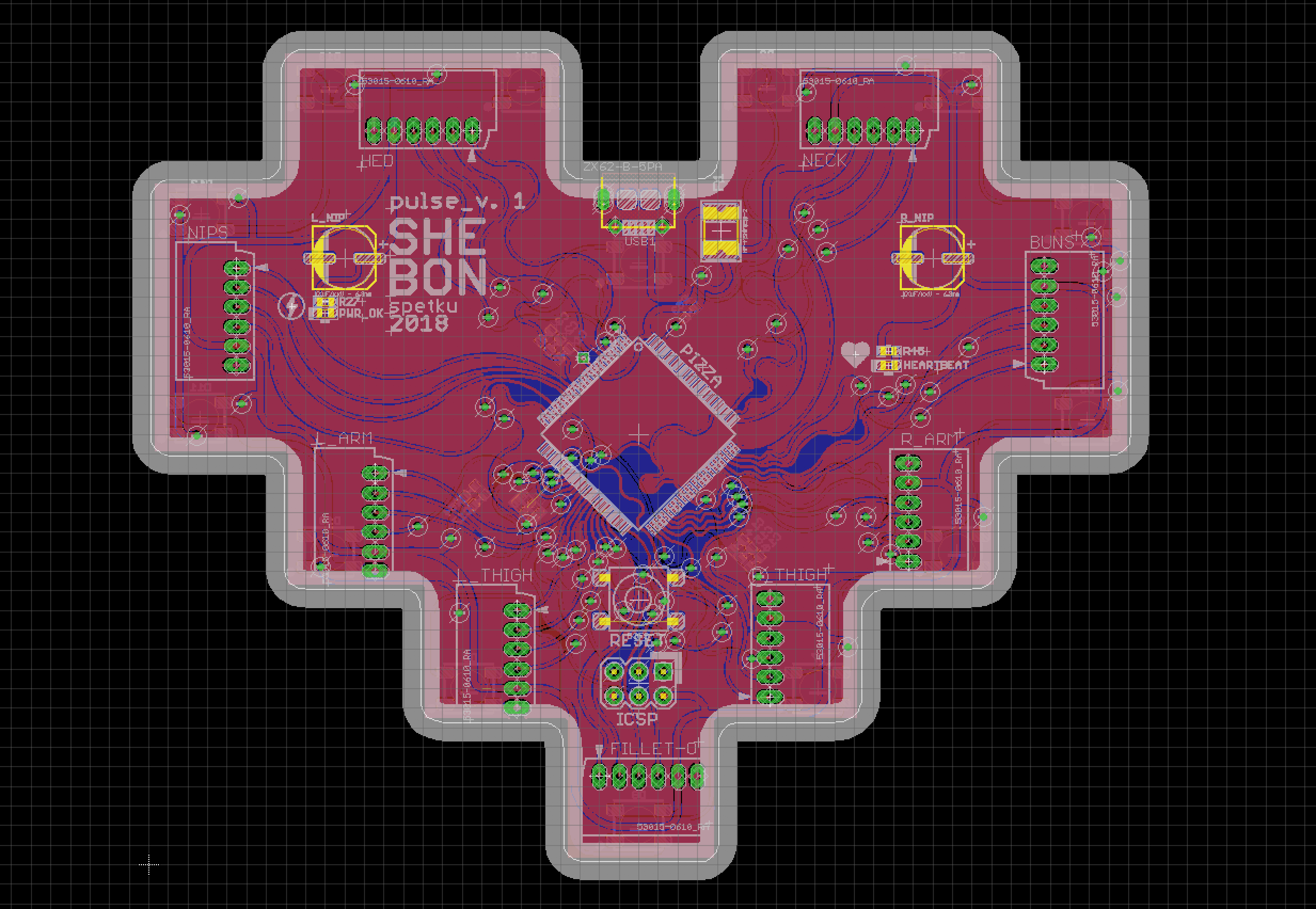
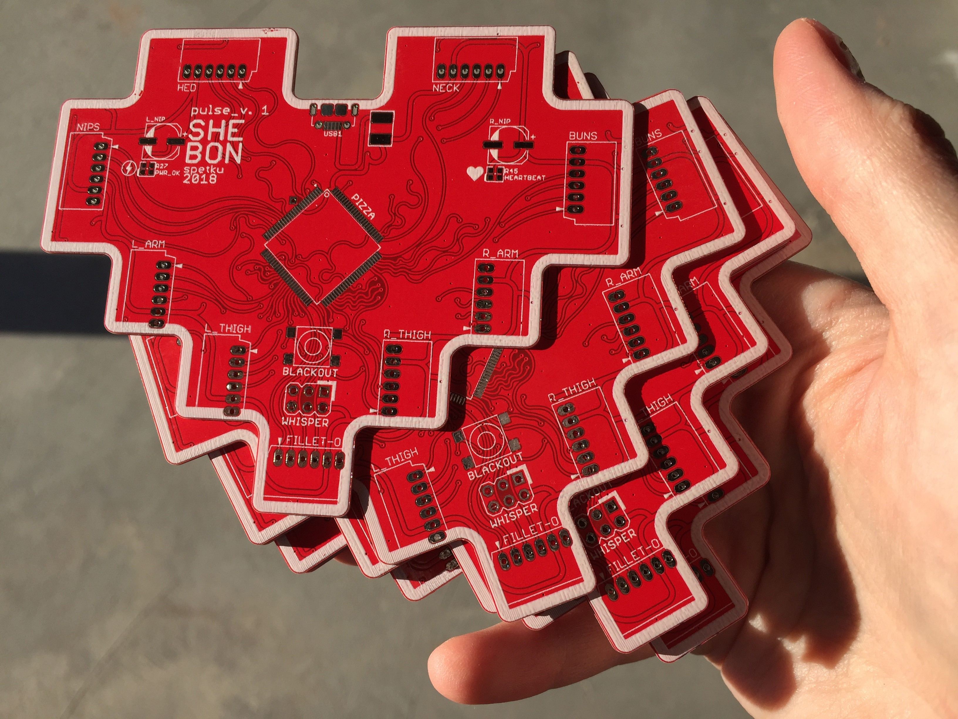
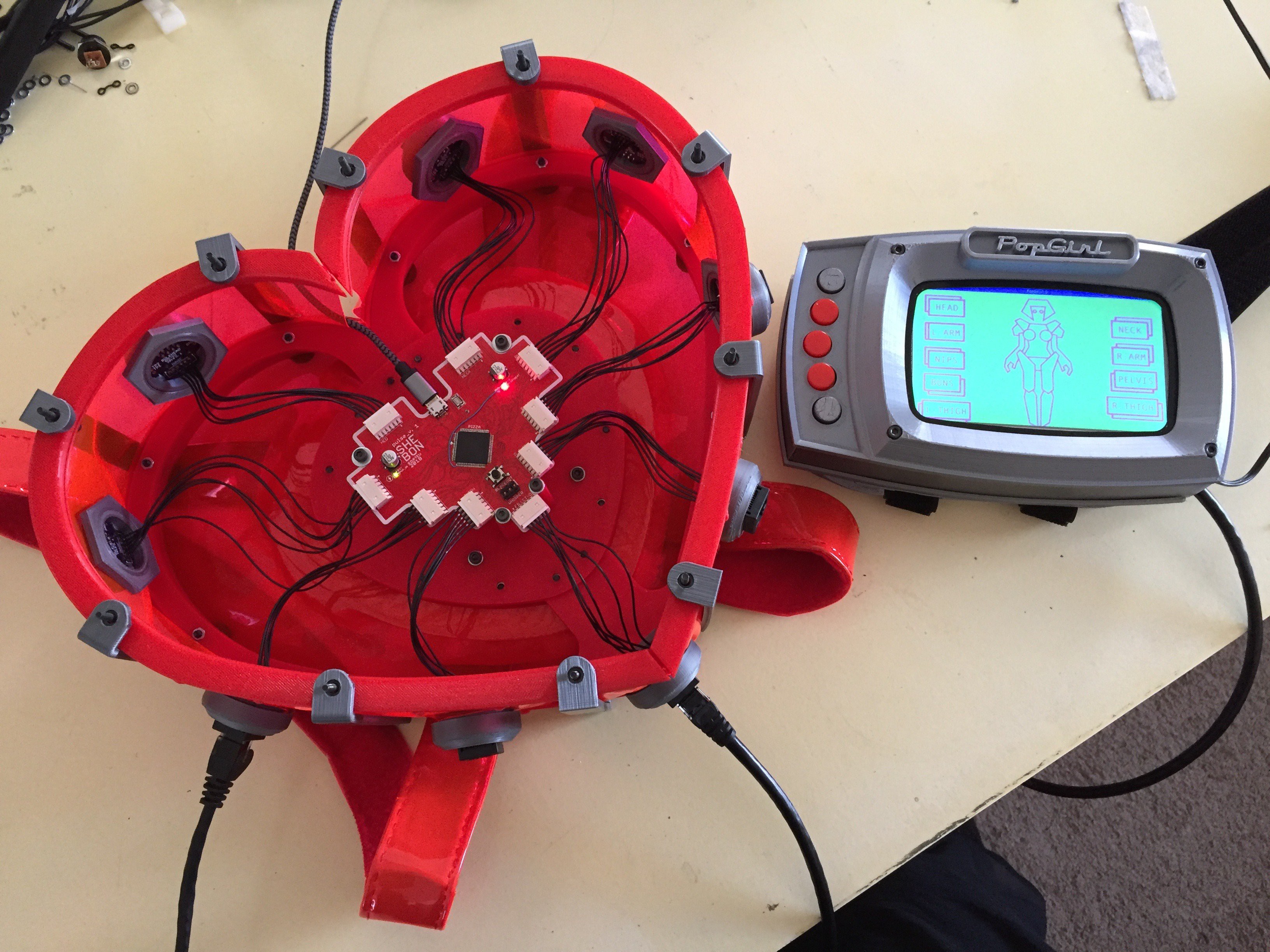
This board is the heart of the SHE BON project. It's nothing horrifically fancy - however I've designed it to serve the specific functions of the project.
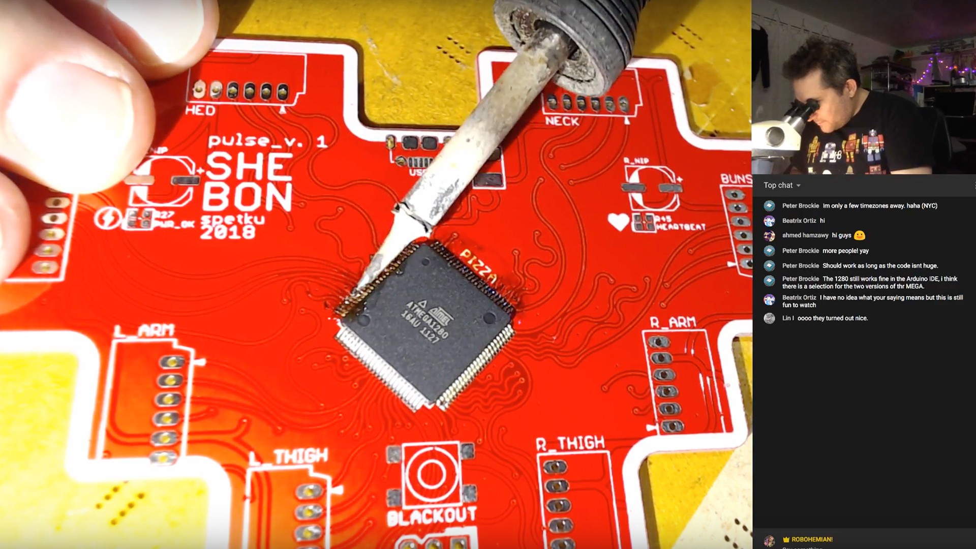
It is equipped with an ATMega 1280 (like the Arduino MEGA)- and is broken out to 9 molex connectors along its edge, which are meant to serve power and data to multiple subsystems.
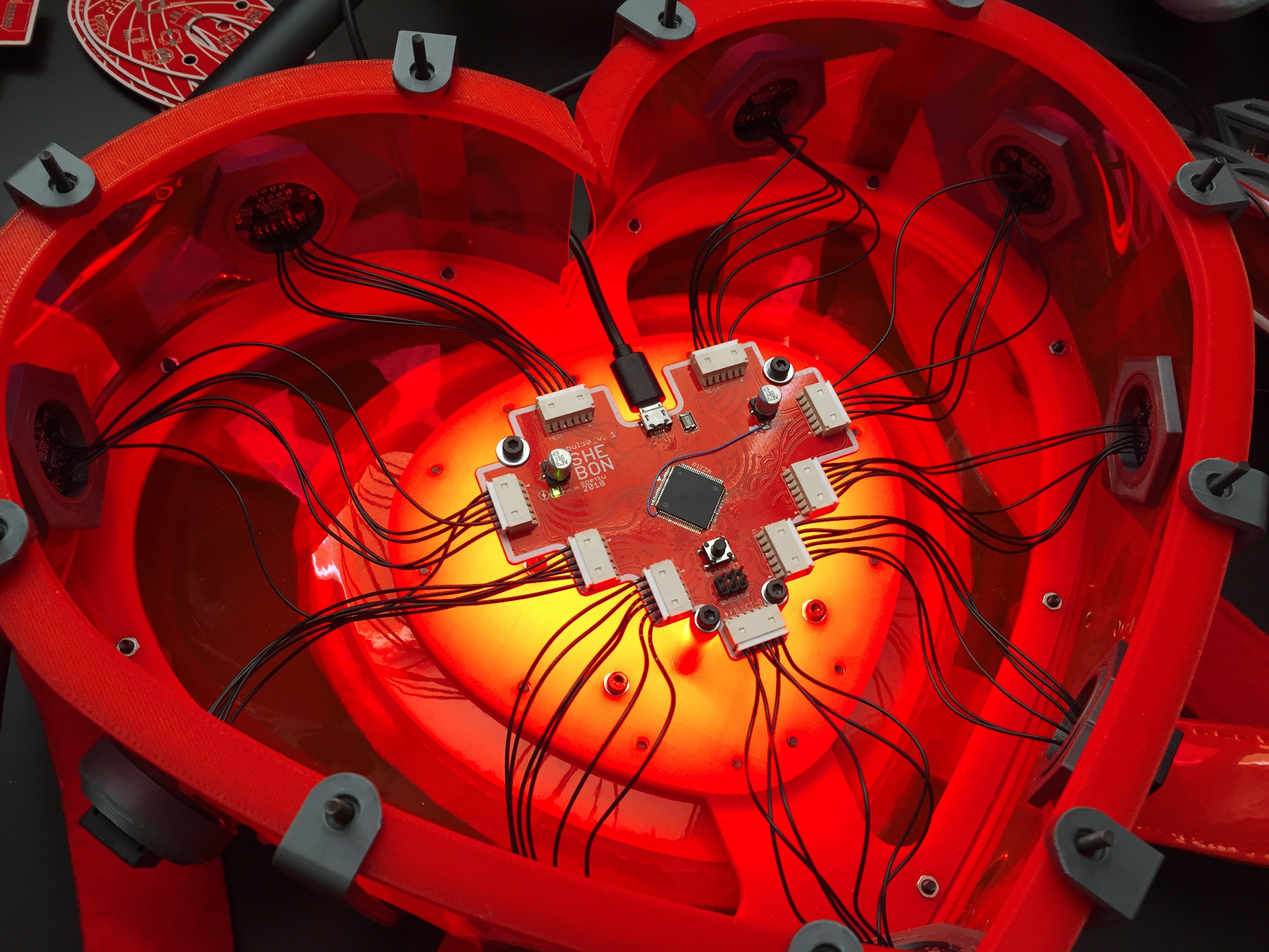
It has been designed to mount inside of something- and in this case for the SHE BON project- I've mounted it inside of a backpack wearable, with the MOLEX connectors terminating at the backpack's edges at RJ45 connectors.
![]()
ASSEMBLING YOUR OWN PULSE BOARD
If you'd like to save yourself some trouble, you can buy this board directly from me on Tindie. However, the layout is open source, so if you feel so inclined, you may have your own fabricated.
The bill of materials can be found on my SHE BON gitHub, as well on the project page here on hackaday.io
THE NEXT REVISION OF THE PULSE
I mentioned above that this board serves much the same use as an Arduino MEGA (its io pins are just distributed all fancy like).
While this board will get you started, whether you're a beginner or vetted hacker, there are some improvements I'm making to the next iteration of the PULSE that will give it some vital functionality for the scope of the project.
Rev. 2 of the PULSE will include:
- an SD card reader for logging data
- a small eINK display for status indication
- possibly different connectors along the edge
![]()
If you personally have an suggestions on how I could improve this board for its intended use, please let me know! I'm admittedly more of a mechanical person than an electronics buff, so it's likely I don't know what possible! :)
-
POPgirl: Raspberry Pi Setup Steps
10/21/2018 at 05:58 • 0 commentsPopGirl Hardware and Software
Much of this is typed from memory and may be missing a step or some other detail here or there. Please feel free to share any corrections or contact us to help you get through a step that is failing.
In a nutshell:
- Set up a RaspberryPi Zero W with a fresh Raspian.
- Enable SSH and VNC.
- Disable the serial console.
- Increase the GPU RAM allocation to 128MB.
- Remove the Oracle Java and install OpenJava and OpenJavaFX.
- Install Pi4J
- Install WiringPi to version 1.2 or newer.
- Test our JavaFX based app.
- Automate the app startup at boot time.
HARDWARE
The PopGirl uses a Raspberry Pi Zero W to drive a AdaFruit 5" LCD with touch panel. The serial port pins (RX and TX) on the GPIO connector are level translated to 5V signal levels for communication with the heart shaped sensor processor board that is located in the heart-shaped backpack.
The sensor board collects and formats sensor data and then bursts them over the serial line once every half-second. The Raspberry Pi listens for this packet and decodes the values into their respective display values.
RASPBERRY PI ZERO
Configure a microSD card to run "Raspian with Desktop" from:
https://www.raspberrypi.org/downloads/raspbian/
If you are new to Raspberry Pi, there are a number of utilities to burn the Raspian image to the SD card. On our Mac, we used: Apple Pi Baker https://www.tweaking4all.com/?s=apple+pi
At first, you should hook your Raspberry Pi up to a regular monitor, keyboard and mouse. Boot the system up.
You will want to ultimately enable SSH and VNC so that you can administer and test the app from the comfort of your PC or Mac. Here is a link for how to enable SSH and VNC. Any other services should be left alone at this point as we don't use them.
https://www.raspberrypi.org/documentation/remote-access/
Disable Serial Console (because we need to use it for our hardware).
Read this to understand how to configure the serial: https://www.raspberrypi.org/documentation/configuration/uart.md
See the section called "Disabling Linux's use of console UART"
SOFTWARE
The PopGirl app is written in JavaFX using OpenJava8 but also leverages Pi4J and WiringPi to allow serial port communication as well as GPIO functions. There are a number of steps to get the stock Raspberry Pi ready for running the Java application.
The Oracle Java8 that is included with the Raspbian distribution will not work for JavaFX. Oracle has decided to decouple JavaFX from the core Java going forward. Future versions of Java will have a better mechanism for add JavaFX as an optional module, but for now we need to uninstall the Oracle Java and replace it with OpenJava. Then we can add the OpenJFX library.
Remove Oracle Java:
sudo apt-get remove --purge oracle-java8-jdk
Add Open Java:
sudo apt-get install openjava openjfx
WiringPi (to access the GPIO/Serial pins from Java)
The version of wiring-pi should be 1.2 or above. If it's 1.1 then you need to replace it:
curl -s get.pi4j.com | sudo bash
This Pi4J reference may also help: http://pi4j.com/install.html
GPU Memory Setting:
From the Desktop go to: [Menu] --> [Preferences] --> [Raspberry pi config..] --> [Performance]
Adjust the GPU memory to 128
APPLICATION
At this point, JavaFX applications should run OK.
Hiding the mouse cursor
Since we are using a touch screen, we want the mouse cursor to disappear. There's an app for that:
https://spellfoundry.com/2016/05/29/configuring-gpio-serial-port-raspbian-jessie-including-pi-3/
Let's assume that your Java app is called "PopGirl.jar" and you uploaded it into /home/pi/
Notice that we need to tell java to set the pi4j.linking=dynamic property so that it uses the newer version of WiringPi.
Running the app from the command line (you will need to set the X-display screen number):
export DISPLAY=:0
/usr/bin/java -Dpi4j.linking=dynamic -jar /home/pi/PopGirl.jar
If that's all working, then lets make the JAR start at boot.
Autostarting the app:
Edit: ~/.config/lxsession/LXDE-pi/autostart
Add this line to the end of the file (notice it starts with @ symbol):
@/usr/bin/java -Dpi4j.linking=dynamic -jar /home/pi/PopGirl.jar
The app should start up ten or so seconds after the desktop comes up.
If you need to debug why the app might not be coming up on it's own then look in this log file for clues:
cat /home/pi/.cache/lxsession/LXDE-pi/run.log
-
POPgirl : Hardware & Enclosure Build
10/11/2018 at 05:06 • 0 commentsI made a status indicator that notifies me of my body's relative state of arousal!
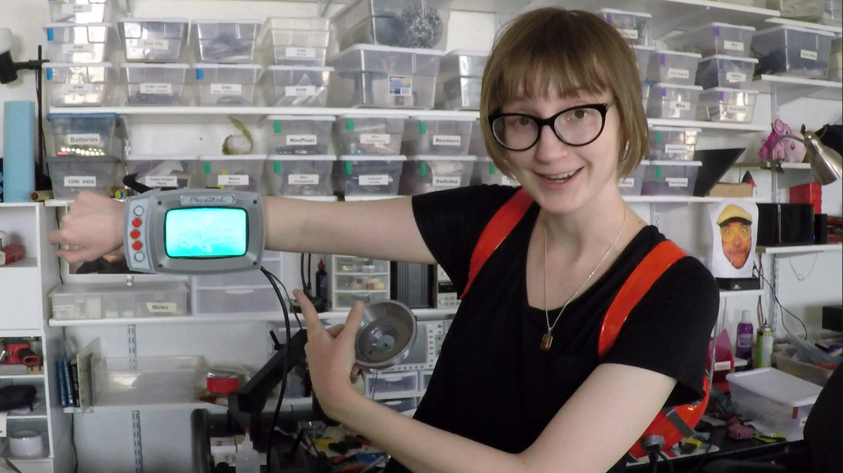
To help me visualize what's going on with the myriad of wearables I have set out to don at once, I've created an arm-mounted screen display that will tell me what I need to know at a glance.
The development of this little treat was of course a matter of hardware design and software development, so I'm breaking the build log into two parts. This first edition will cover the physical components, like the electronics, the enclosure for the electronics, and any other bells and whistles I needed to create to make it do.
BILL OF MATERIALS
Electronics stuff:
- 5" Raspberry Pi Compatable Touch Screen
- RaspberryPi Zero
- 5V, 5A Step-Down Voltage Regulator
- Logic Level Converter Bi-Directional Module 5V to 3.3V
- Round Push Buttons
- 1' HDMI cable
- Perf Board
- Stranded Wire
HARDWARE SIZES:
OTHER THINGS YOU'LL NEED:
- soldering iron
- access to a 3D printer
- filament in cool colors
- metric screw driver
- pliers
- sleet plastic (up to 1/16 inch thick)
- patience*
*I say you'll need patience, but really... you will need to perform some light modification of some cables in order to get them to fit within the profile of the enclosure. Specifically, you'll need to strip some of the casing from a USB mini cable, as well as strip the plug casing from an HDMI cable. =O
We'll talk more about that later.
THE PRINTED STUFF
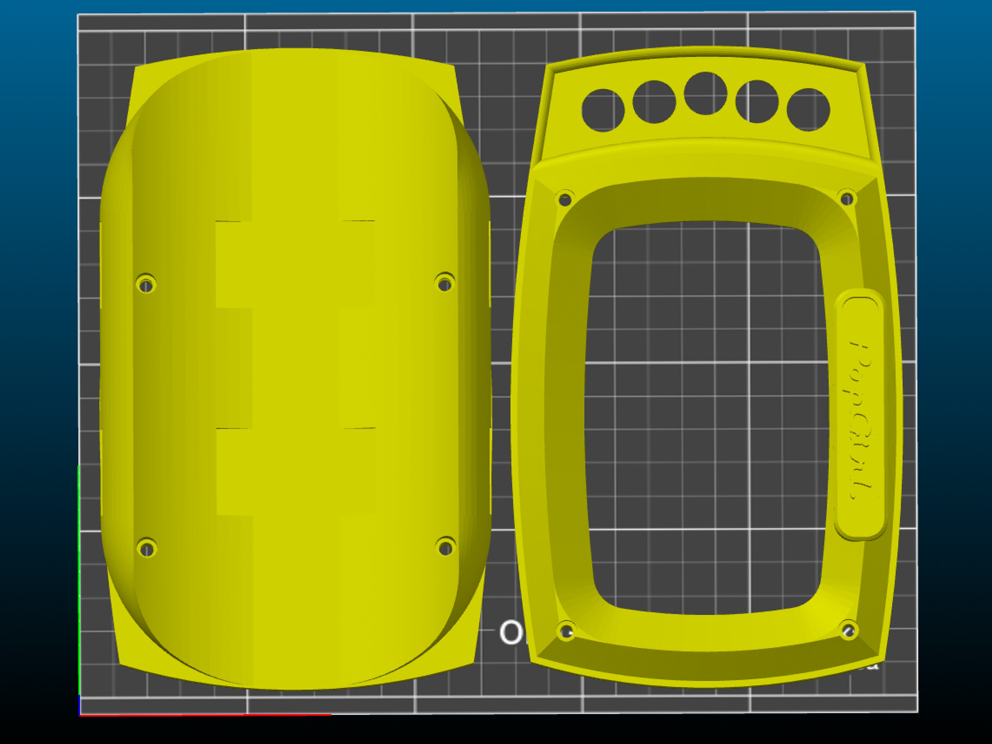
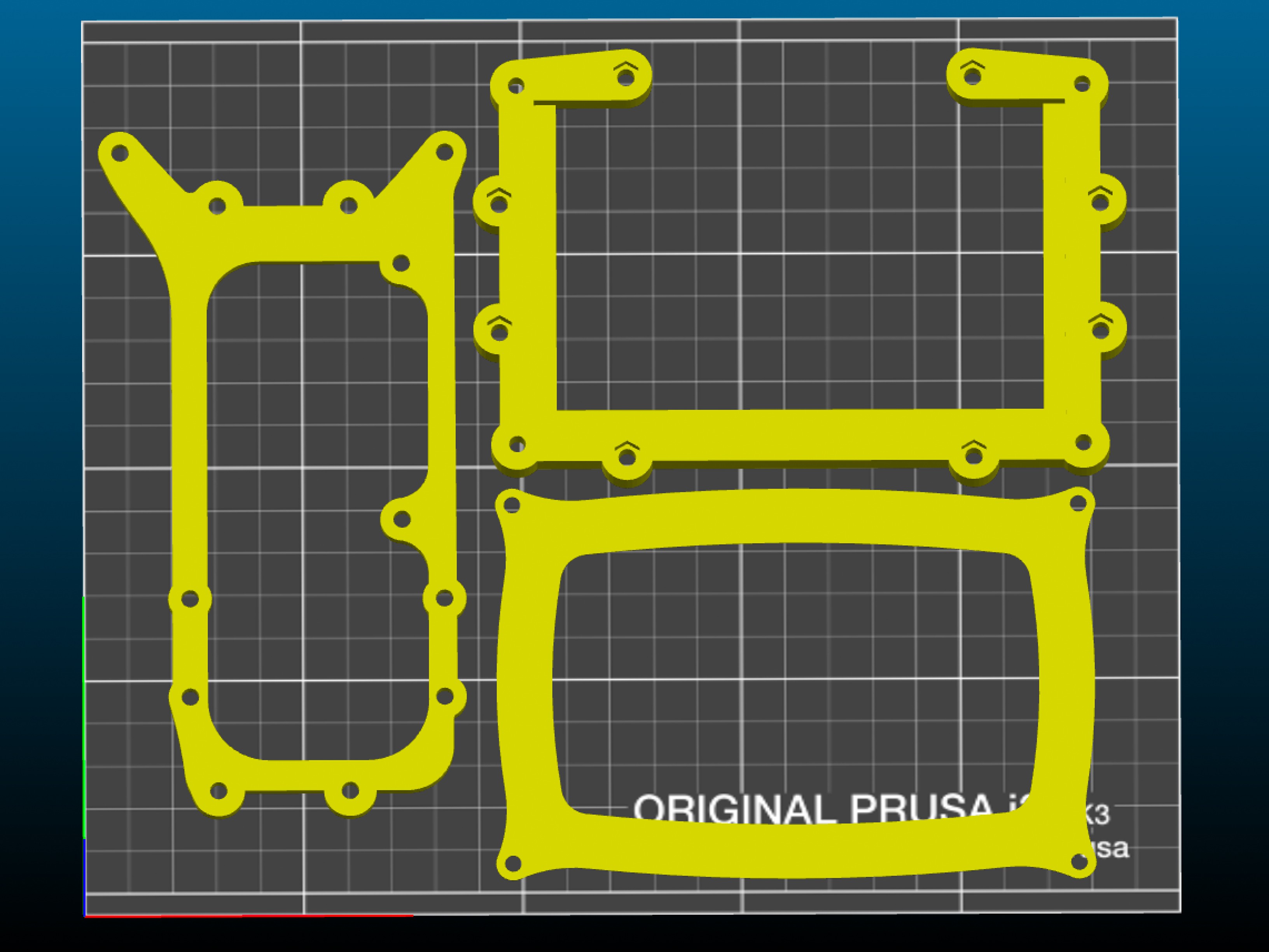
You'll be glad to know that there are only 5 core pieces you'll need to print in order to make your own POPgirl enclosure.
The .stl files can be found on my SHE BON gitHub repo!
The bad news is that a couple of them will take close to six hours to print a piece.
Stylistically, I chose to print the enclosure in silver and black... but you can use whatever colors of filament you'd like, of course. Here are the two trays of parts according to the color they'll be represented as in these build instructions:
SILVER PARTS:
![]()
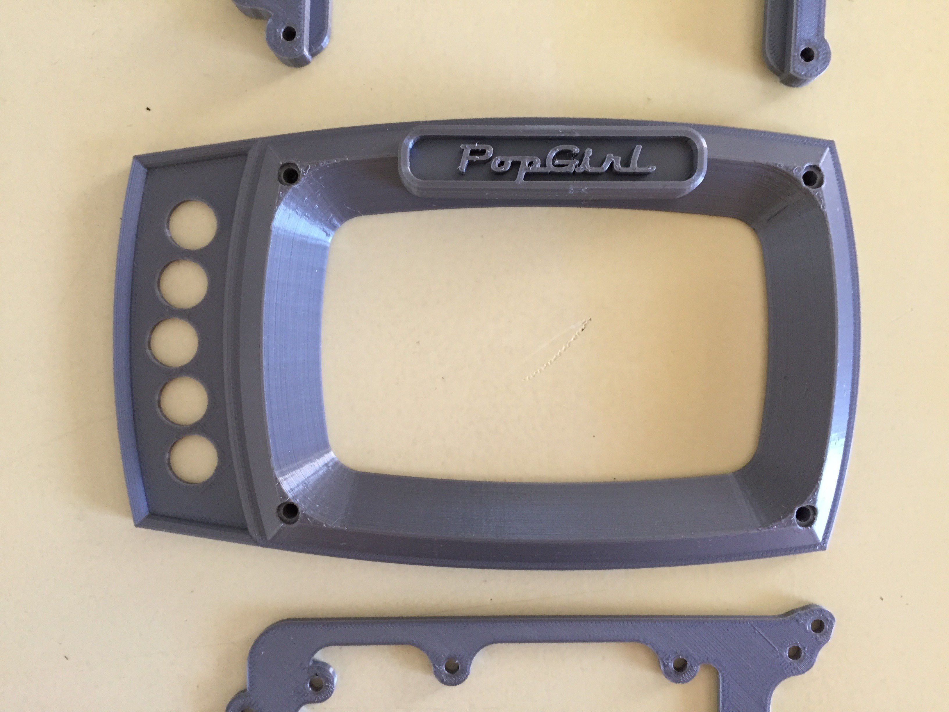
- face_plate (~7 hours)
- arm_mount (~8 hours)
BLACK PARTS:
![]()
- PCB_mount (~1 hour)
- screen_frame (~2 hours)
- screen_gasket (5 minutes)
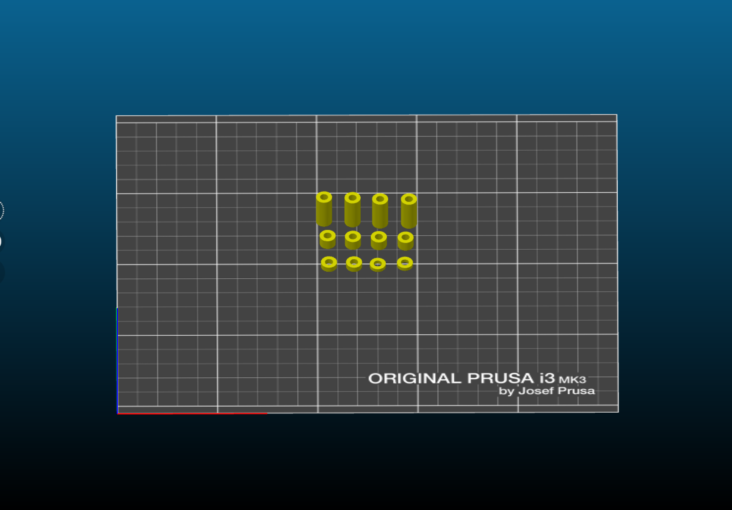
SPACERS:
![]()
In addition to the primary pieces, there are some super important spacers you'll need to print. I chose to print them in red, so they're easy to spot in case they roll off the table into the forever carpet.
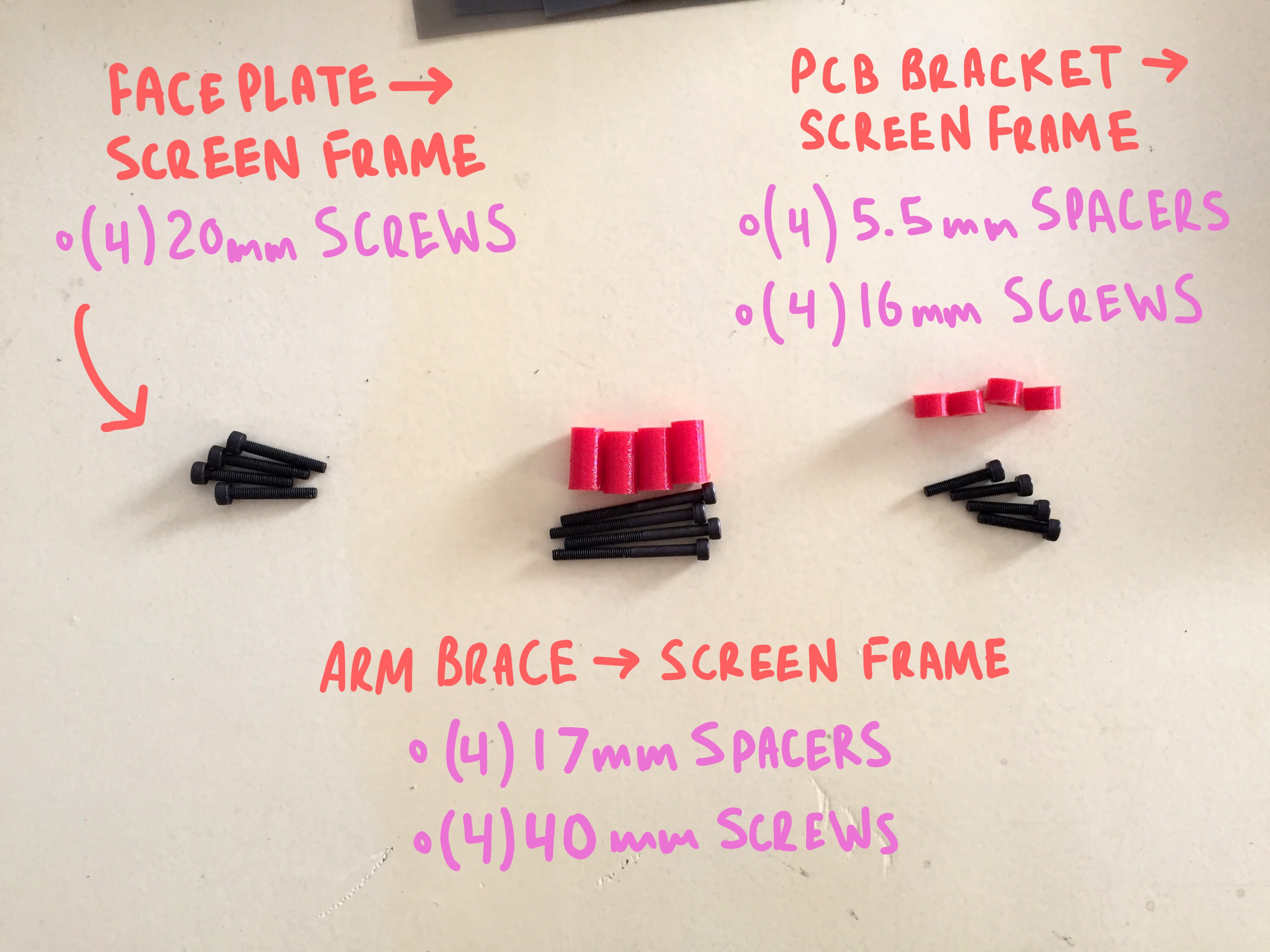
The other important thing to note at this point of the build, is the length of hardware that goes with each space. This is key, because the screw length must be such that it is long enough to reach the countersunk nut it is being screwed into, but not too long otherwise it will bottom out (or poke a hole through the enclosure)
![]()
- (4) 5.5mm
- (4) 17mm
- (2) 2mm
- (2) 3mm
CAPTURING THE SCREEN
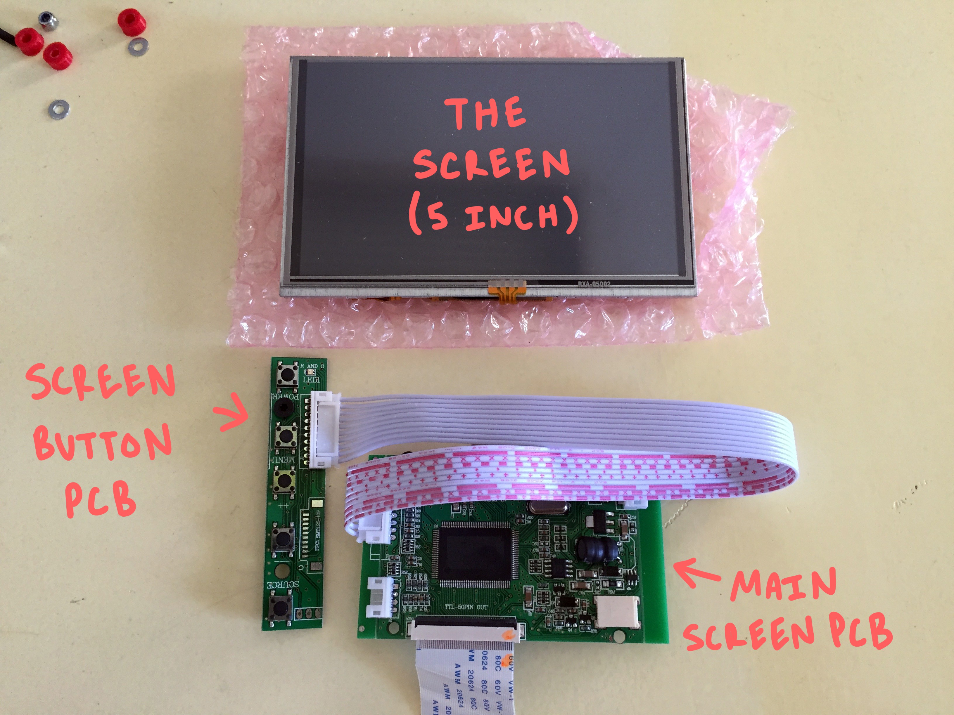
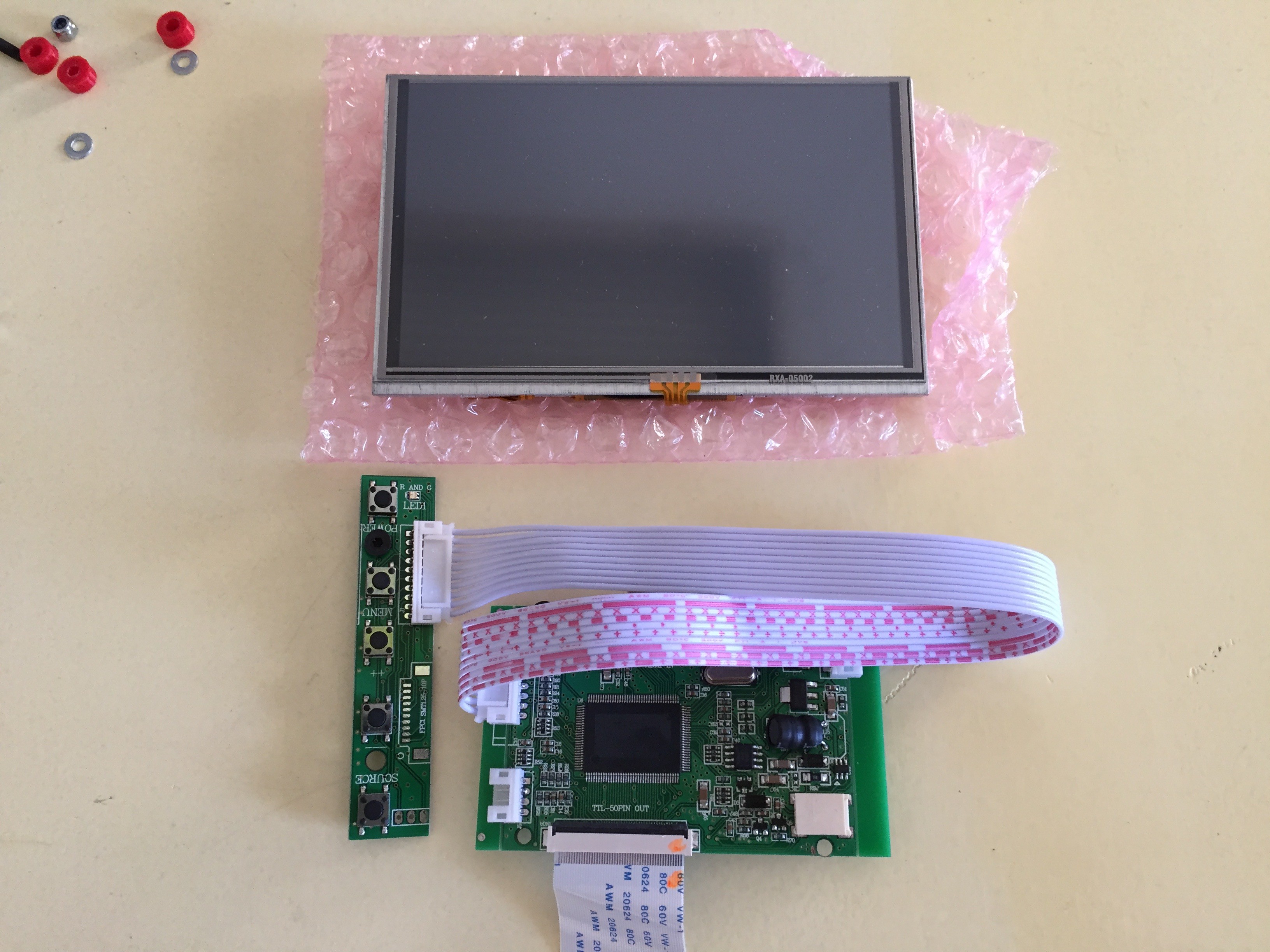
This entire build is constructed around a 5" touchscreen monitor which you can pick up from AdaFruit for ~$80. It's a little awkward to use, as it comes with three horrible PCB tumors hanging off from it at odd angles... but if you take care to secure them in place when you get it, they aren't the worst to work around.
Right away you can disconnect the ribbon between the screen itself and the main PCB, and also unplug the button board all together, as we won't be using it.
![]()
The other helpful thing to do as soon as you unpackaged your screen is to use some double sided silicone tape to adhere the thin and fragile touch-screen PCB directly to the back of the screen to keep it from flopping around all loose-like.
Just tack it down where it wants to lay naturally, and you should be good.
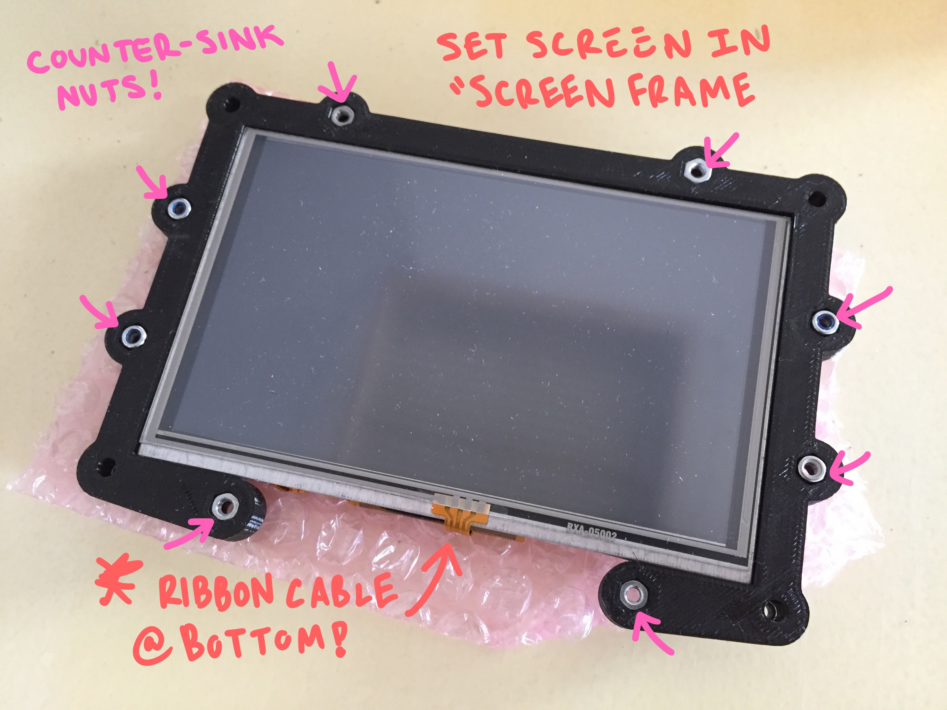
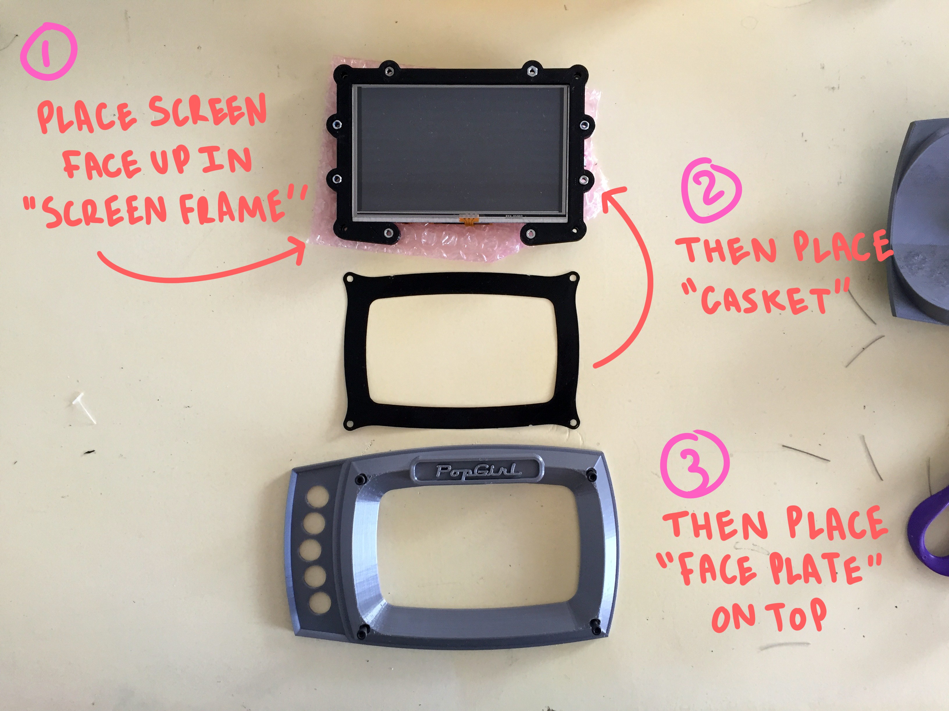
Take the "screen frame" and press-fit some nuts into all of the counter-sunk pockets. There should be (8) on the front, and (4) on the back.
Then lay the back on the screen into the frame so that its front is unobstructed and flush with the printed plastic:
![]()
next, place the thin gasket on top of the screen, lining up the four mounting holes at the corners. It should over-lap and frame the touch-area just slightly.
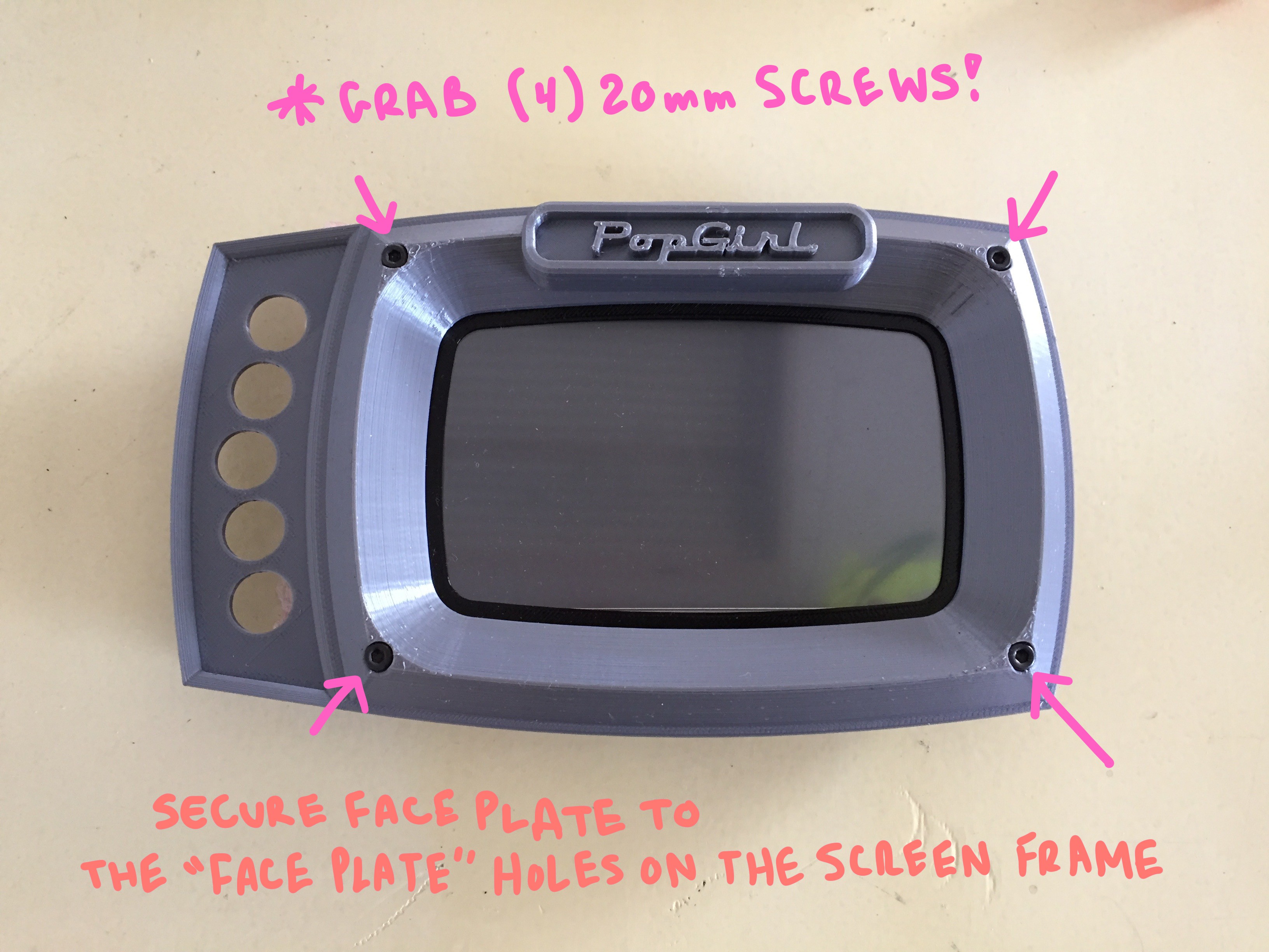
Lastly, the big dance "faceplate" piece should mount directly on top of the gasket. Like up the same hole along the four corners.
![]()
one these three pieces are sandwiched together, you can thread (4) 20mm screws through the from of the "Faceplate" into the corresponding counter-sunk nut holes in the "screen fame":
![]()
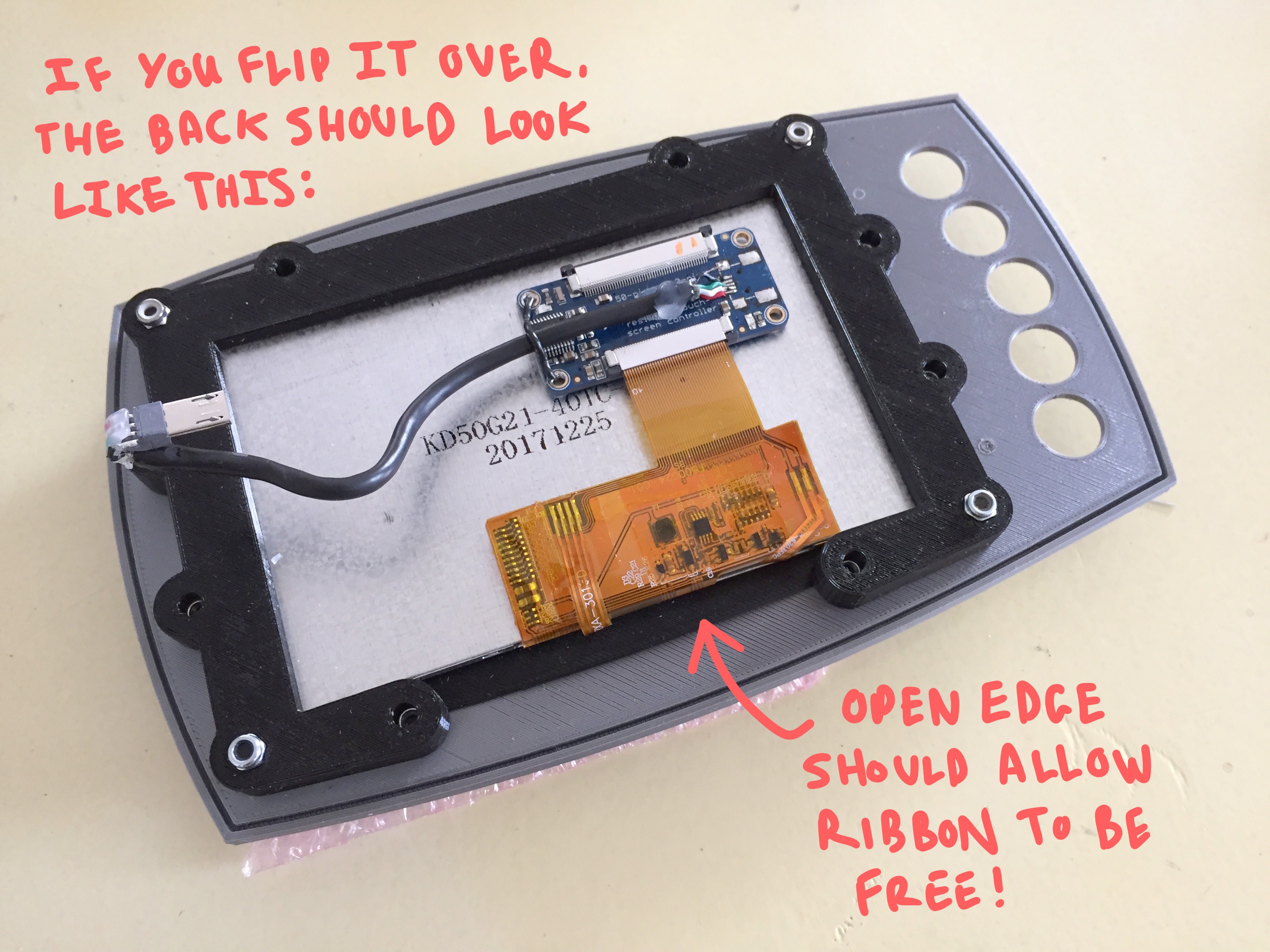
The back should now look like this, with both the ribbon cable and the open edge of the "Screen frame" facing the bottom edge of the assembly:
![]()
MOUNTING THE PCBS TO THE "PCB FRAME"
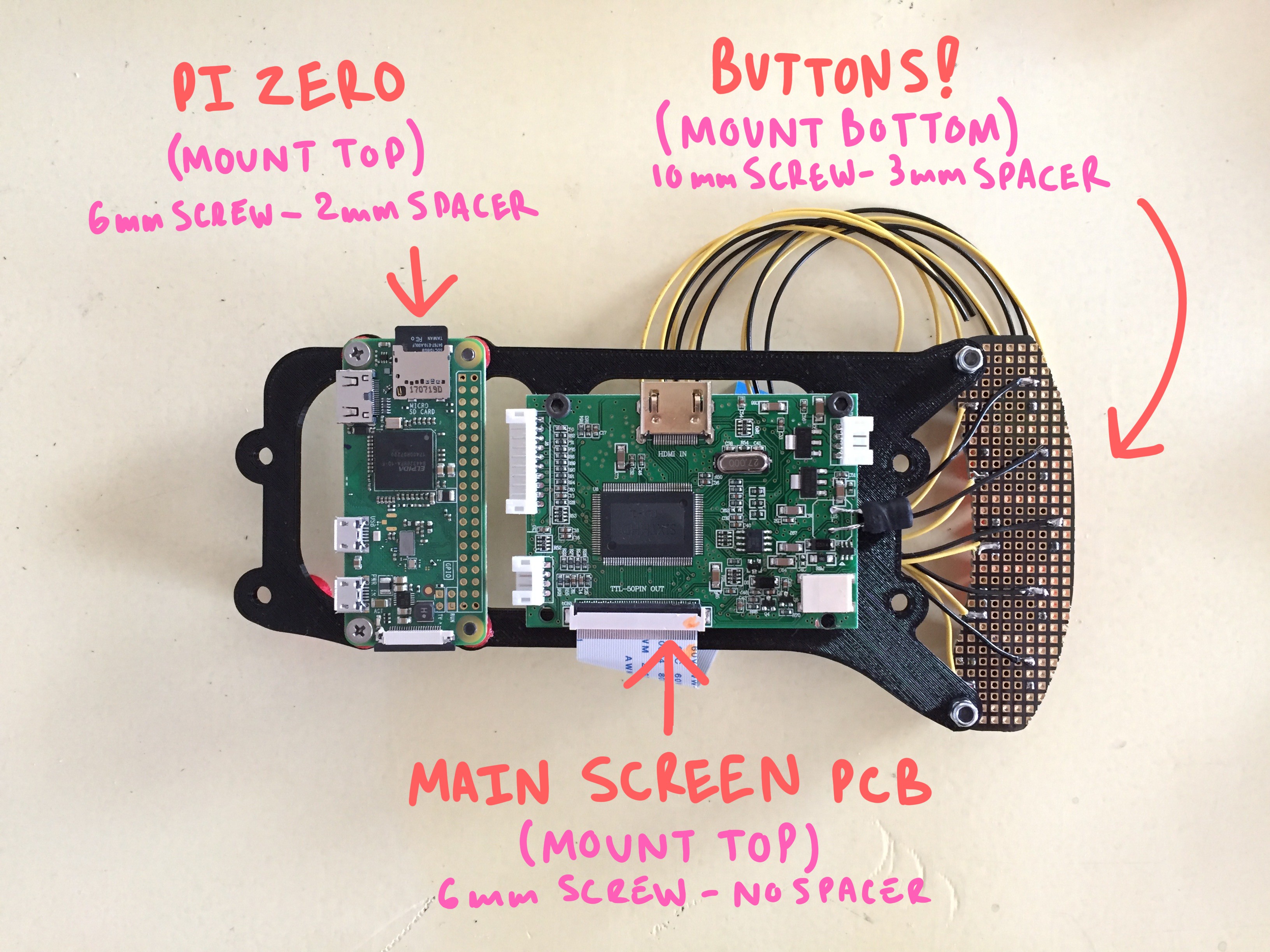
There are three circuit boards that will all share a single mounting frame. On the far left, there should be your "Raspberry Pi Zero", in the center will mount the screen's "primary board", and on the right will mount a "custom button board" that you'll need to put together with some perf-board and those tiny push buttons I listed on the bill of materials.
The completed board should look like this once completed:
![]()
MAKING A CUSTOM BUTTON BOARD
You will need to solder up a quick button board module specifically fit to the clearance holes in the face plate!
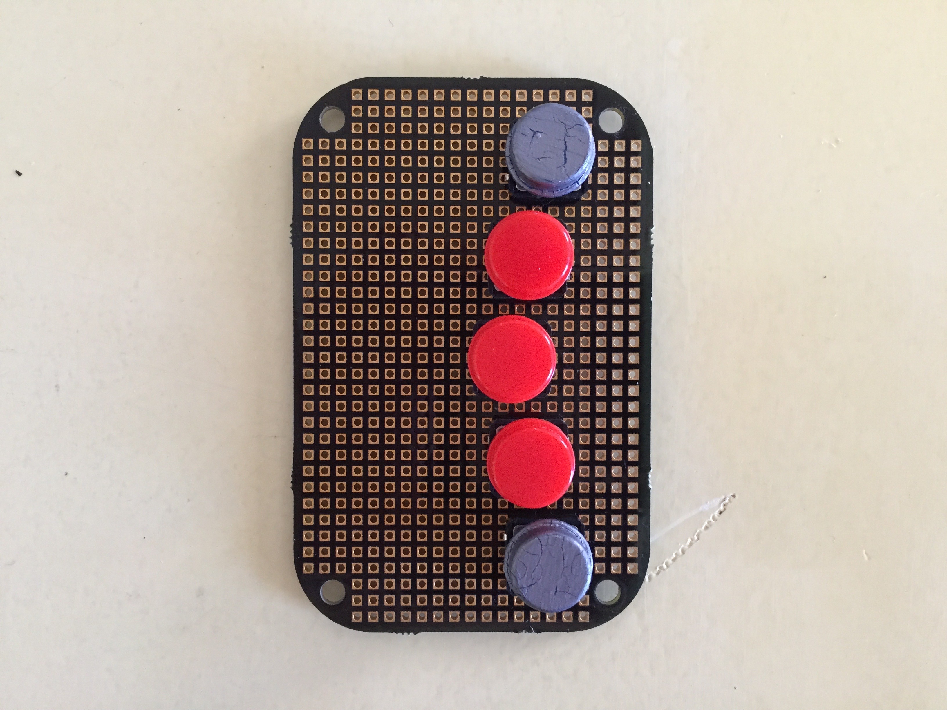
Don't worry! If you have standardly spaced perf board, then you're all set. The front of the board should look like this. Five buttons, staggered by one row in a slight bow to the left:
![]()
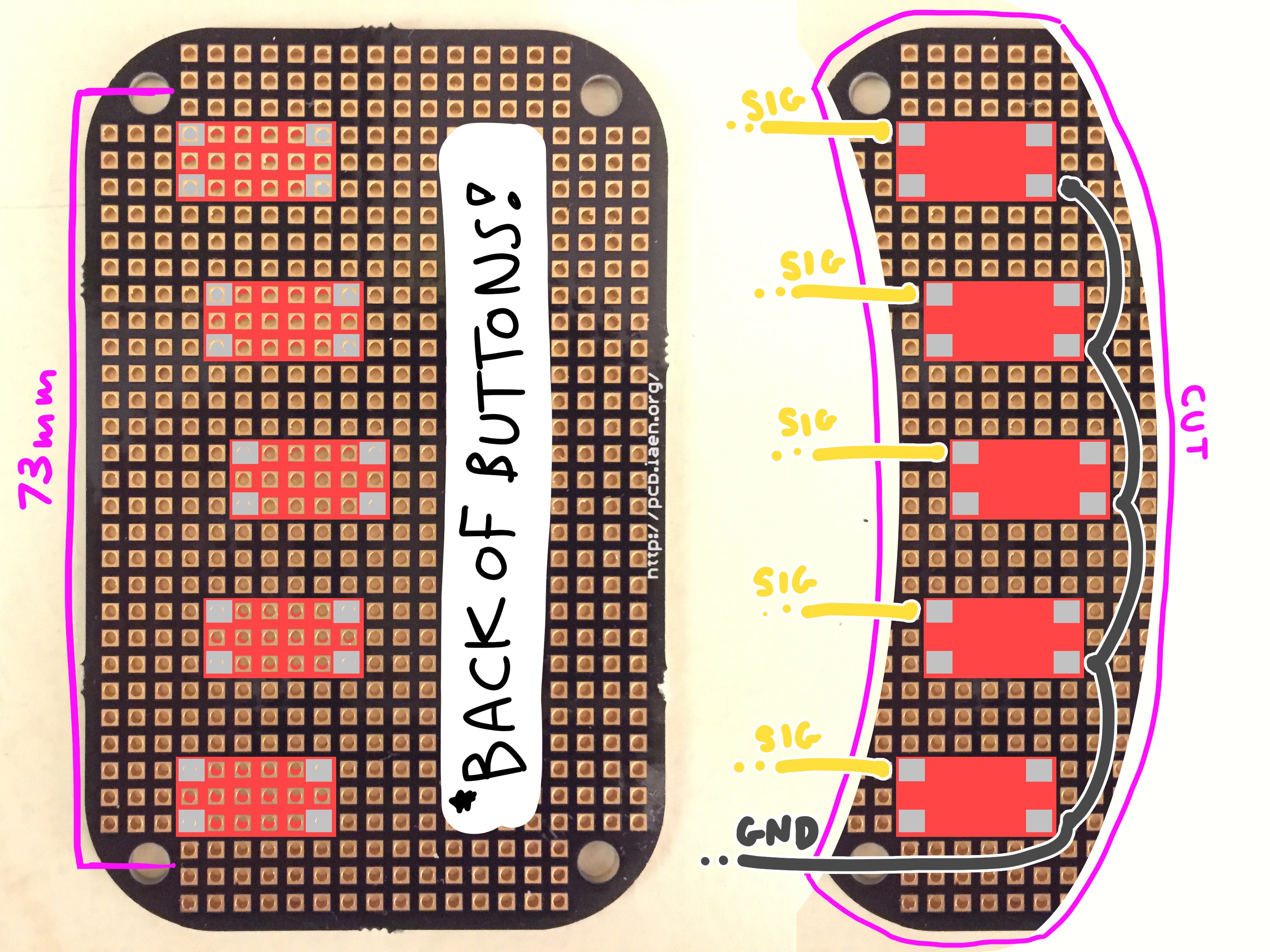
Here is a diagram for the dimensions and space of the buttons as they should fit into the perf board:
![]()
There should be a wire coming off from each button that is ~7" long... and at least on ground wire!
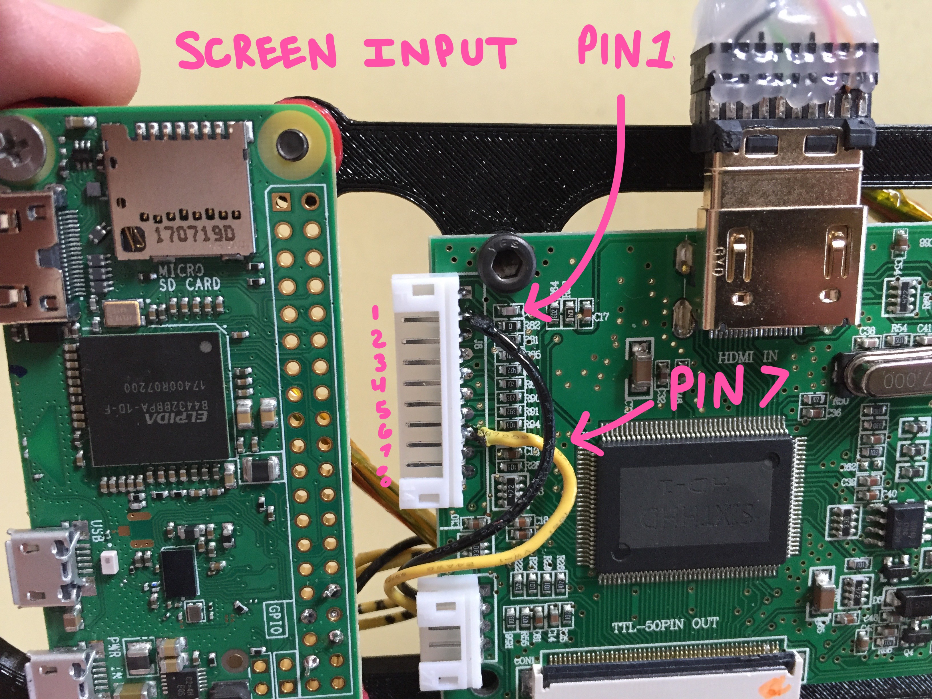
One of your buttons should connect to the "INPUT" of the screen, so that just incase the screen doesn't boot up in the correct mode, you'll be able to easily change it without needed to hook up the whole button bar tumor which came with the screen.
Pick a button, and wire to the pad leading into these two pins of the "button board" connector on the screen's "primary board":
![]()
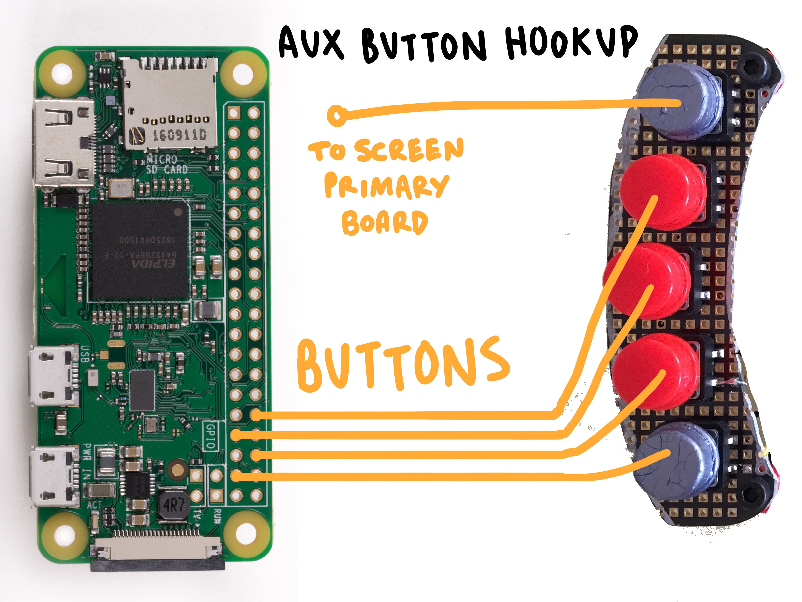
The rest of the buttons on your "custom button board" can be wired into any input pin you'd like on the Raspberry Pi Zero. I personally chose these four pins on the pi:
![]()
CONNECTING THE PCBs TOGETHER
This part kinda sucks. :)
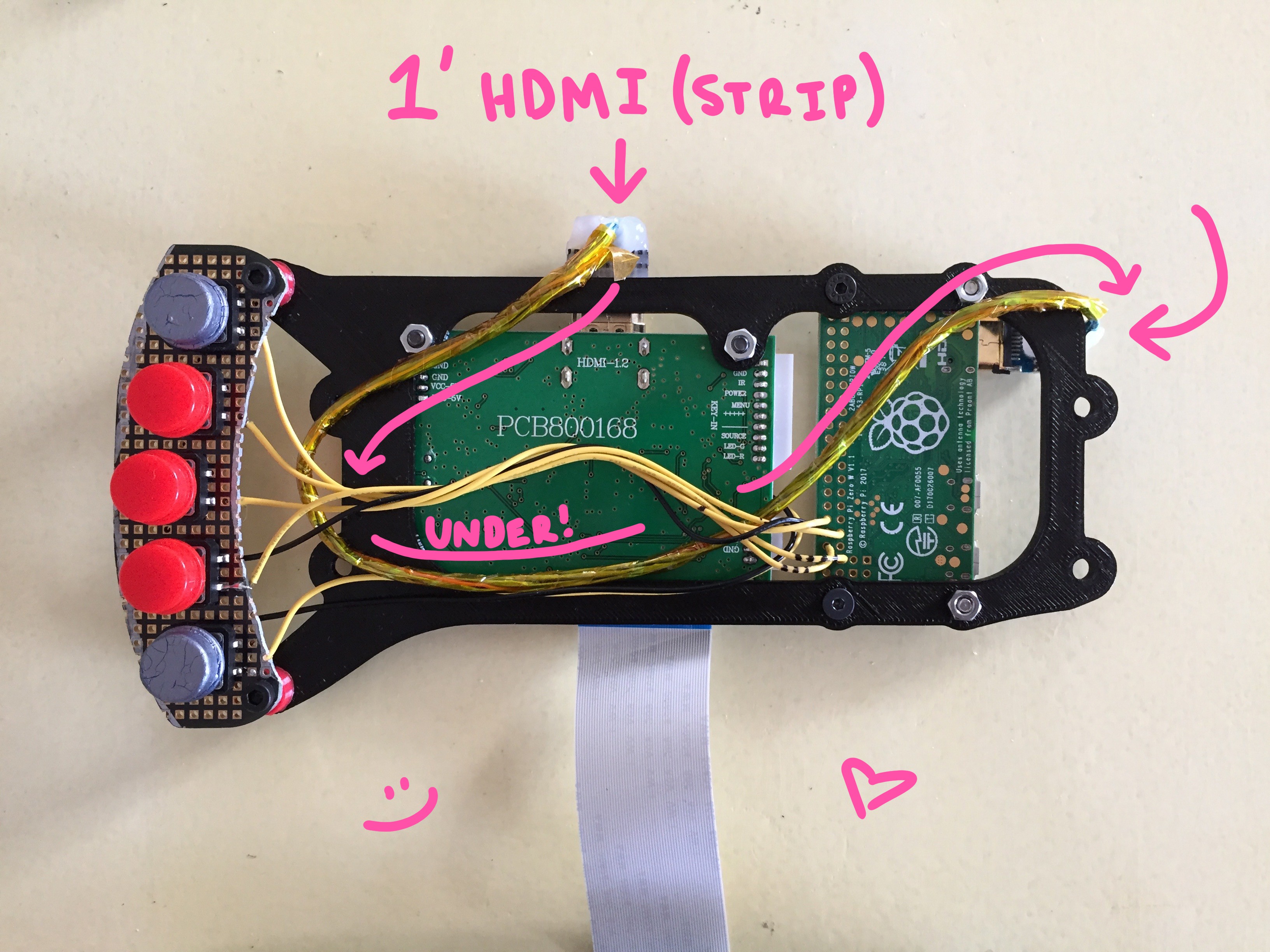
You will have to run *specifically* a 1' HDMI cable from the screen's "primary board" to the "Raspberry Pi" - but in order to get it to fit within the enclosure, you will have to skin it completely. (I will soon post a stream of Mark demonstrating how to do this)
The fully skinned HDMI cable should be routed as such:
![]()
There are eight remaining empty holes on the "screen frame" that will be used for attaching this PCB bracket, as well as for sealing up the enclosure.
ATTACHING THE LOGIC LEVEL CONVERTER
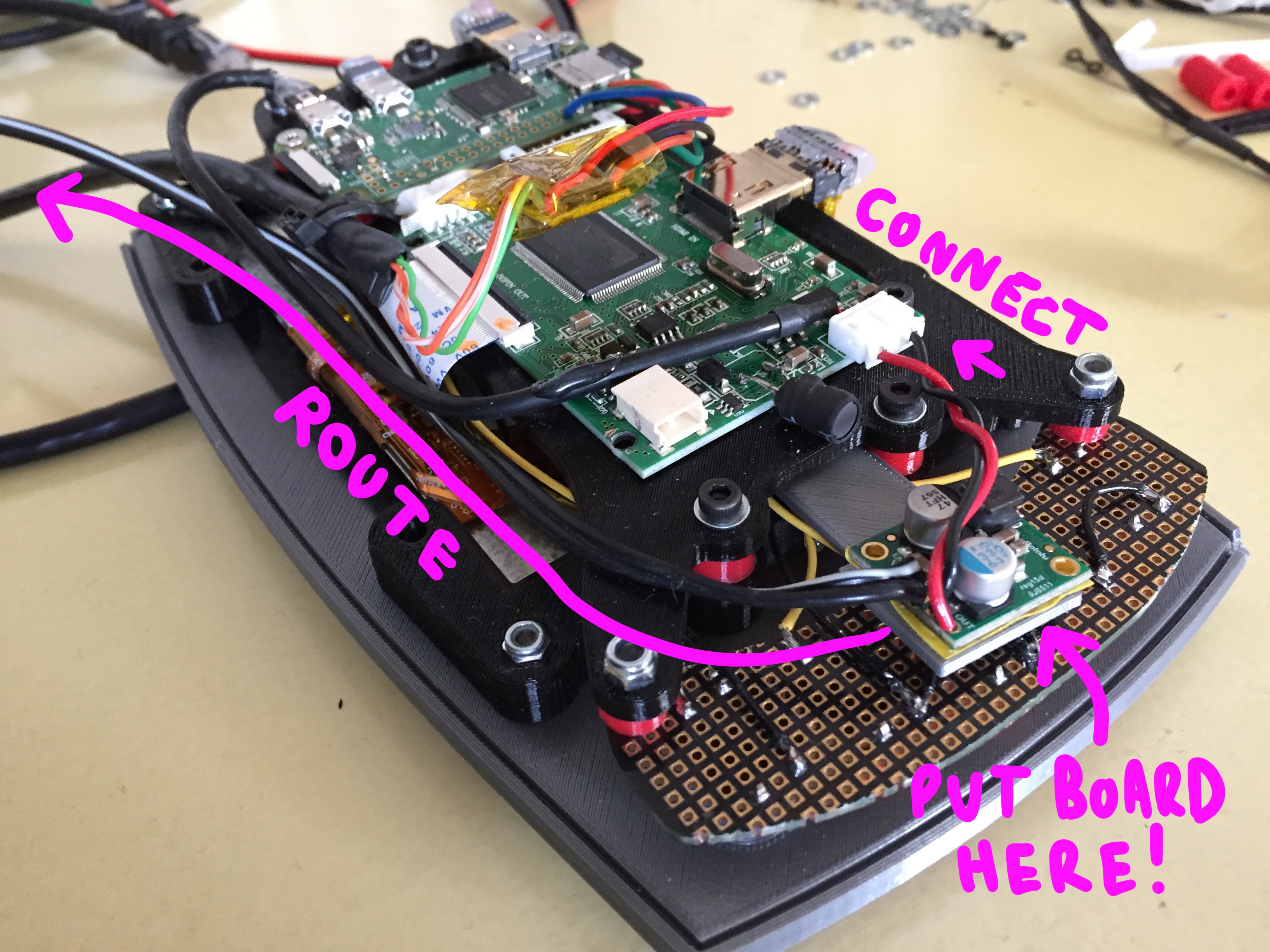
Floating inside of your enclosure, there will exist two voltage regulators. One is a logic converter which drops 5V to 3.3V, there other is for the system in general.
The main voltage converter is available from Pololu.com, and will go between your power supply and the system at large:
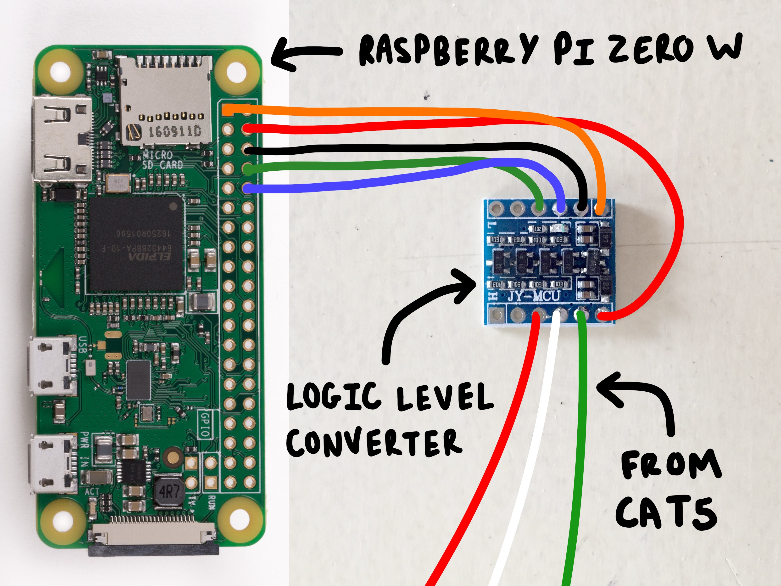
The logic converter is available on Amazon and will go between the Pulse board and the POPgirl's Raspberry Pi Zero board. The stripped end of your cat5 cable will attach to this board, as well as some wire going to your raspberry pi. The hookup will look like this:
![]()
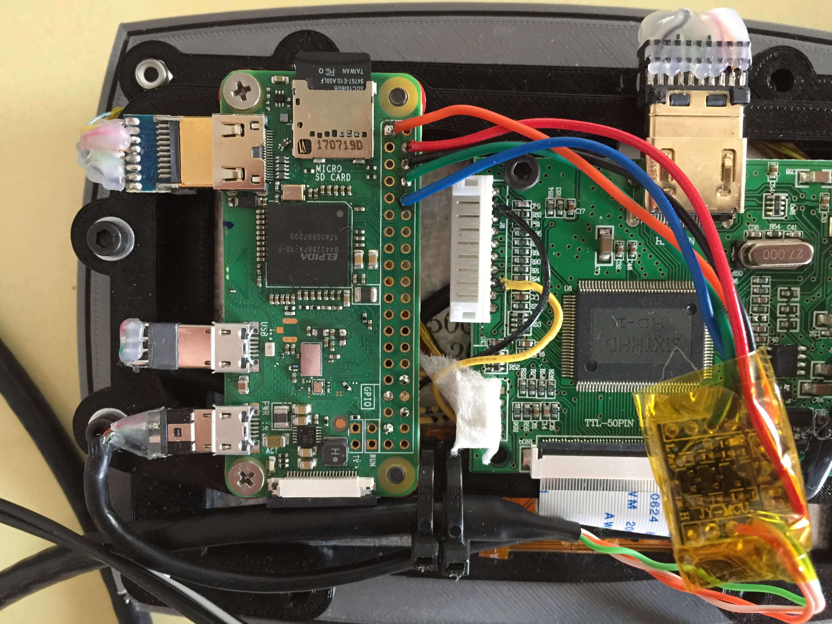
Once its connected, wrap the module in some capton tape and let it rest over the middle the screen's "primary board" like a little floaty tumor:
![]()
ATTACHING THE VOLTAGE REGULATOR
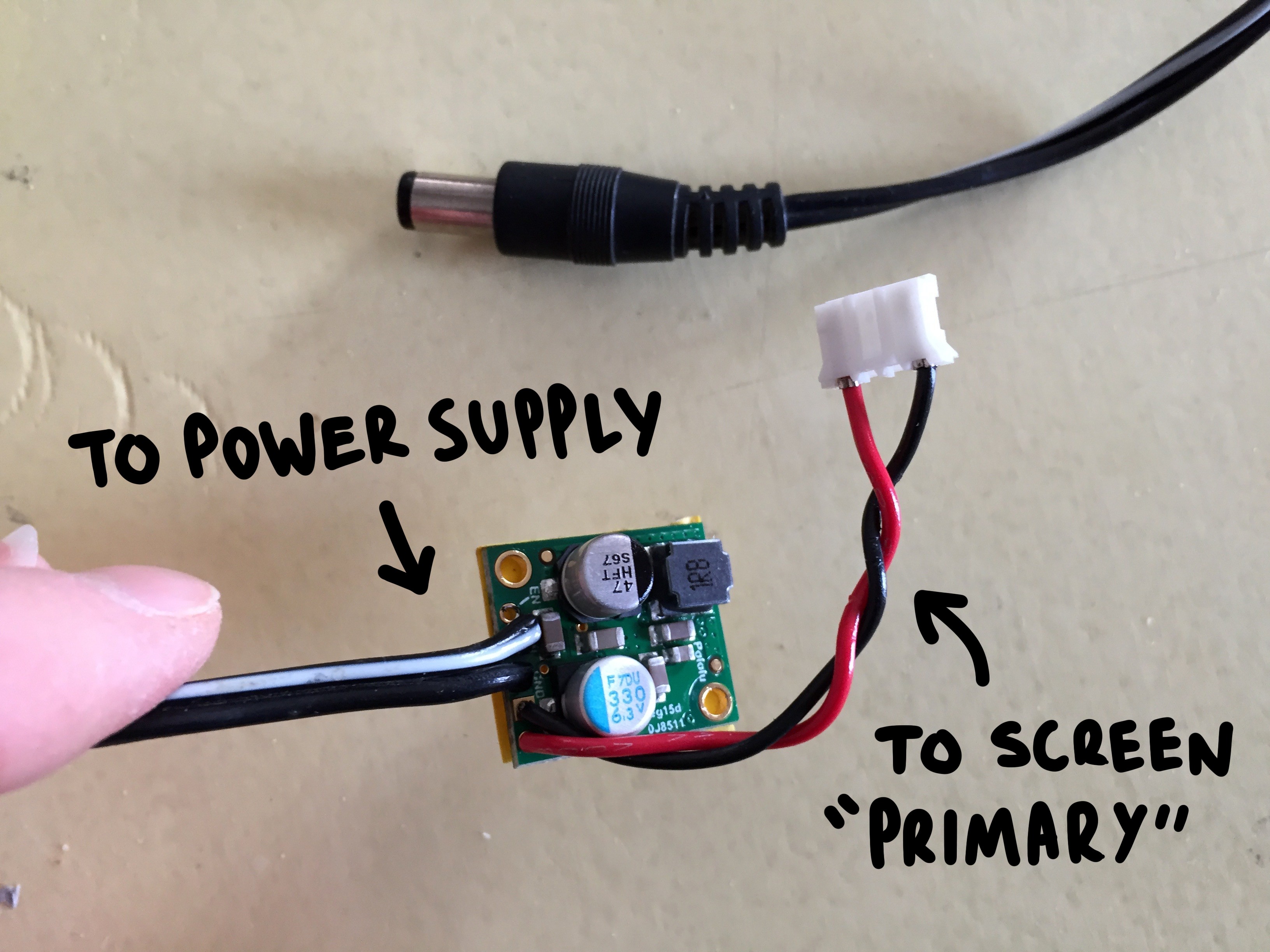
The next tiny glad that you'll need to prepare is the "voltage regulator". You can read more about it on Pololu's specs page!
The cable from your chosen power supply should connect *in* to the board, and the male connector compatible with the screen's "primary pub" should be running *out* from the board:
![]()
Place some electrical tape along the back of the board and wrap it in capton tape to protect it, as this module will more or less "float" inside of the enclosure like a rogue organ:
![]()
The cable running *in* from your power supply should rout along the bottom edge of the enclosure next to the CAT5 data line.
ATTACHING THE *FULLY LOADED* PCB MOUNT
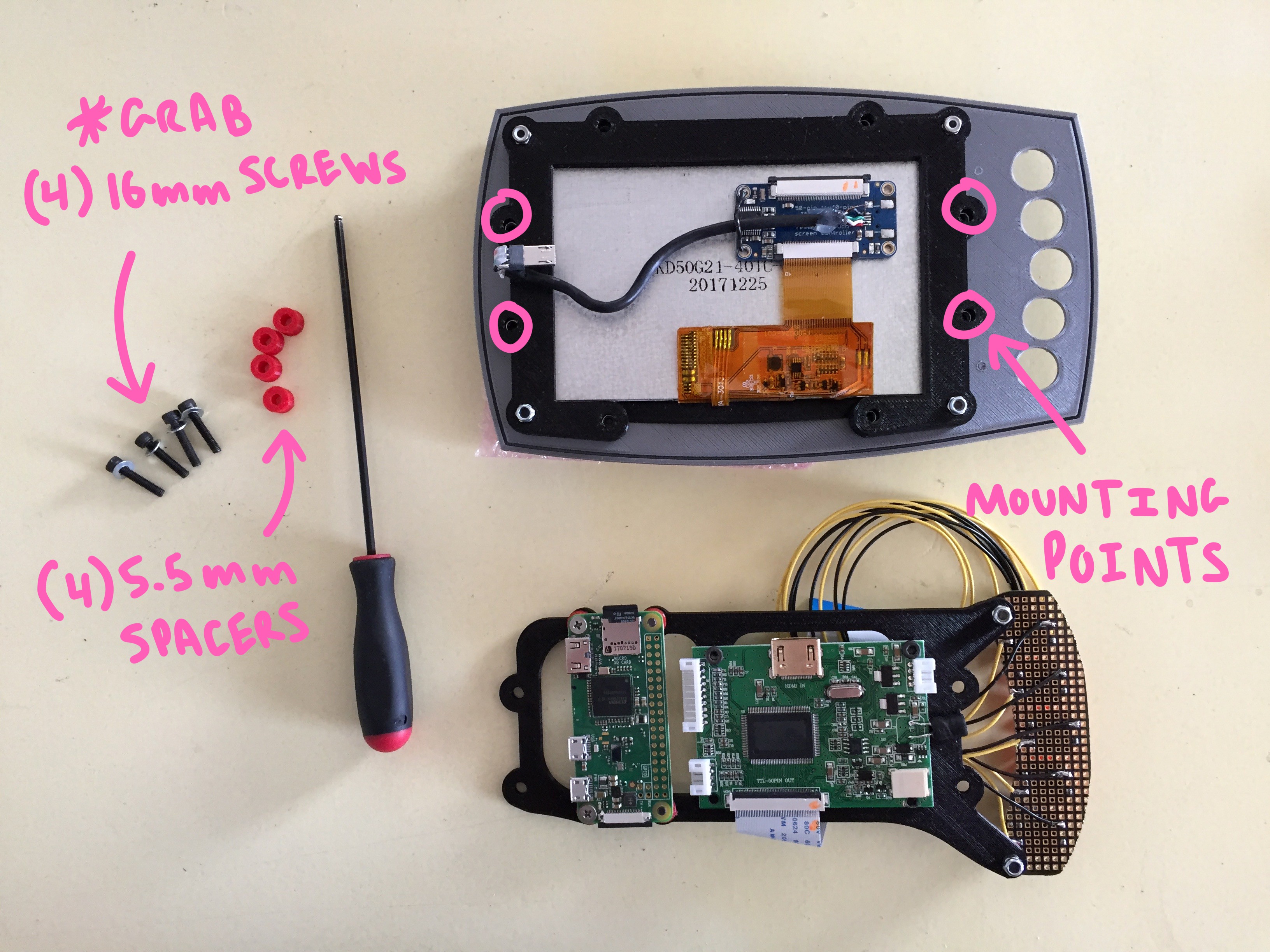
You'll be attaching your loaded PCB bracket to the four holes circled below:
![]()
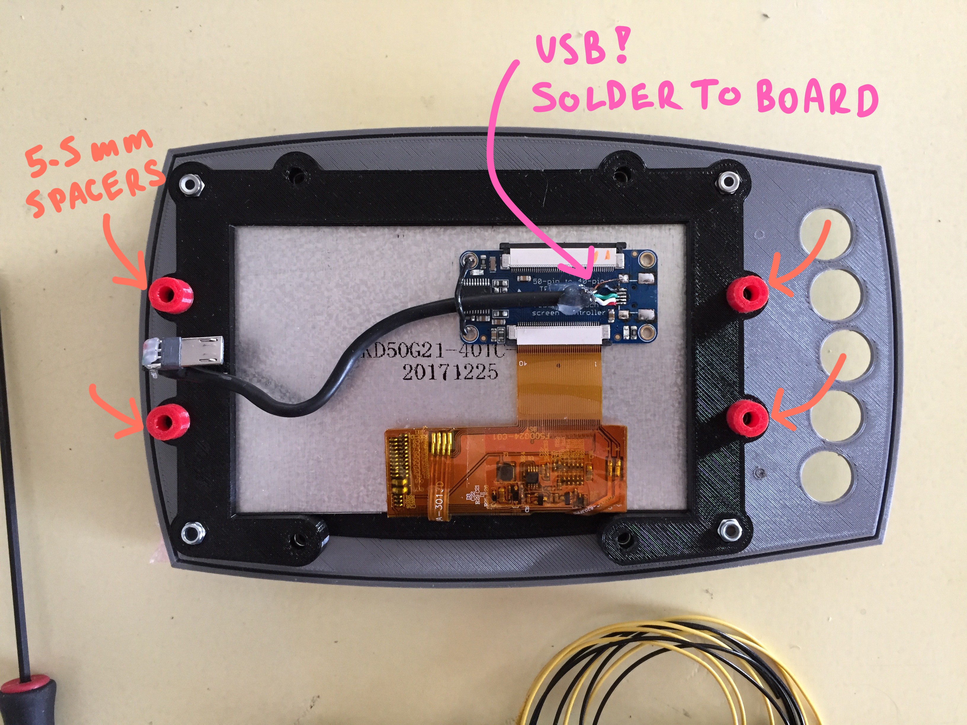
Grab your 5.5mm spacers and position them over these holes:
![]()
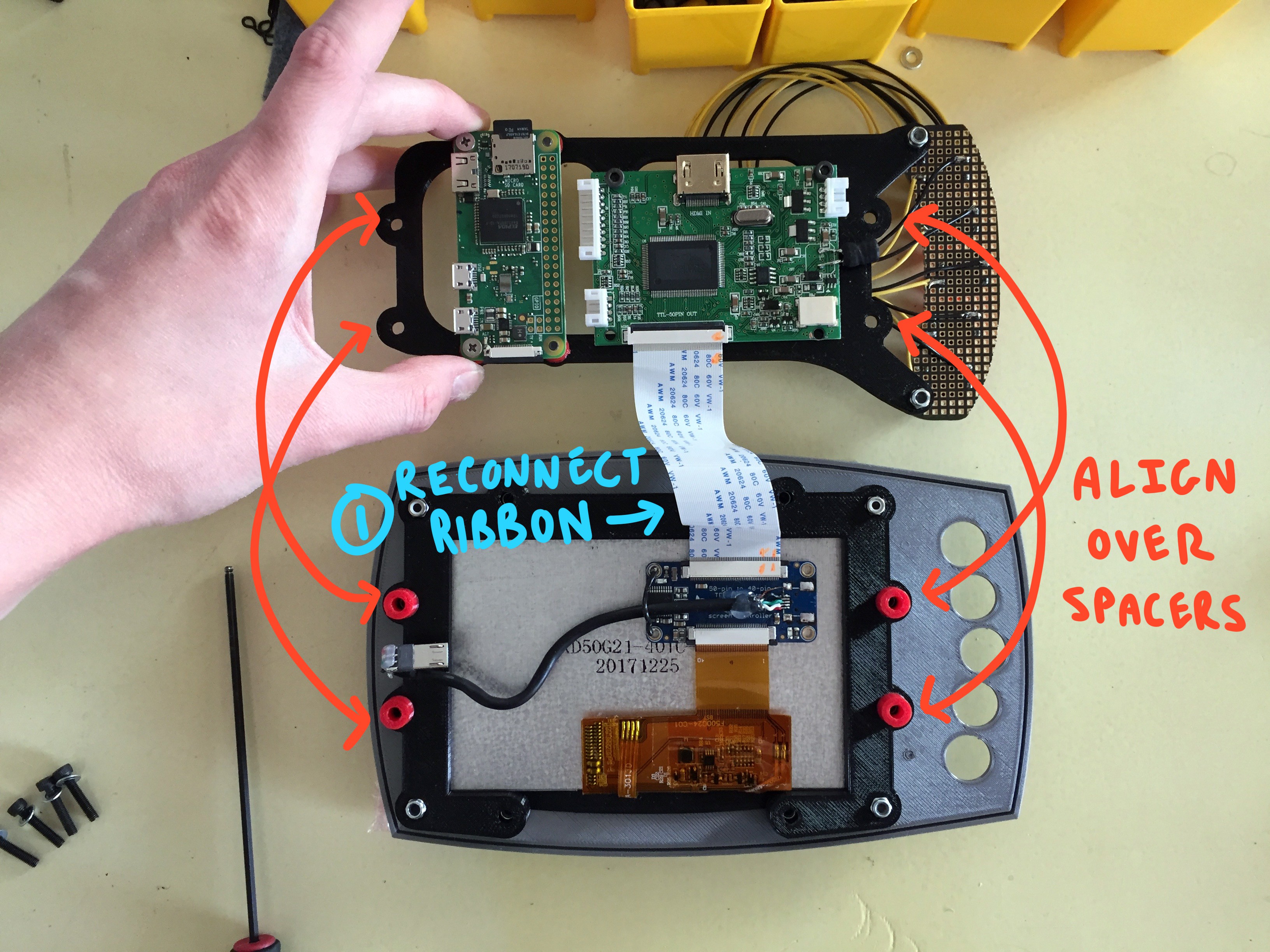
Be sure to reattach your ribbon cable from the touch screen PCB to the main screen board before you position the "PCB bracket" above the spacers:
![]()
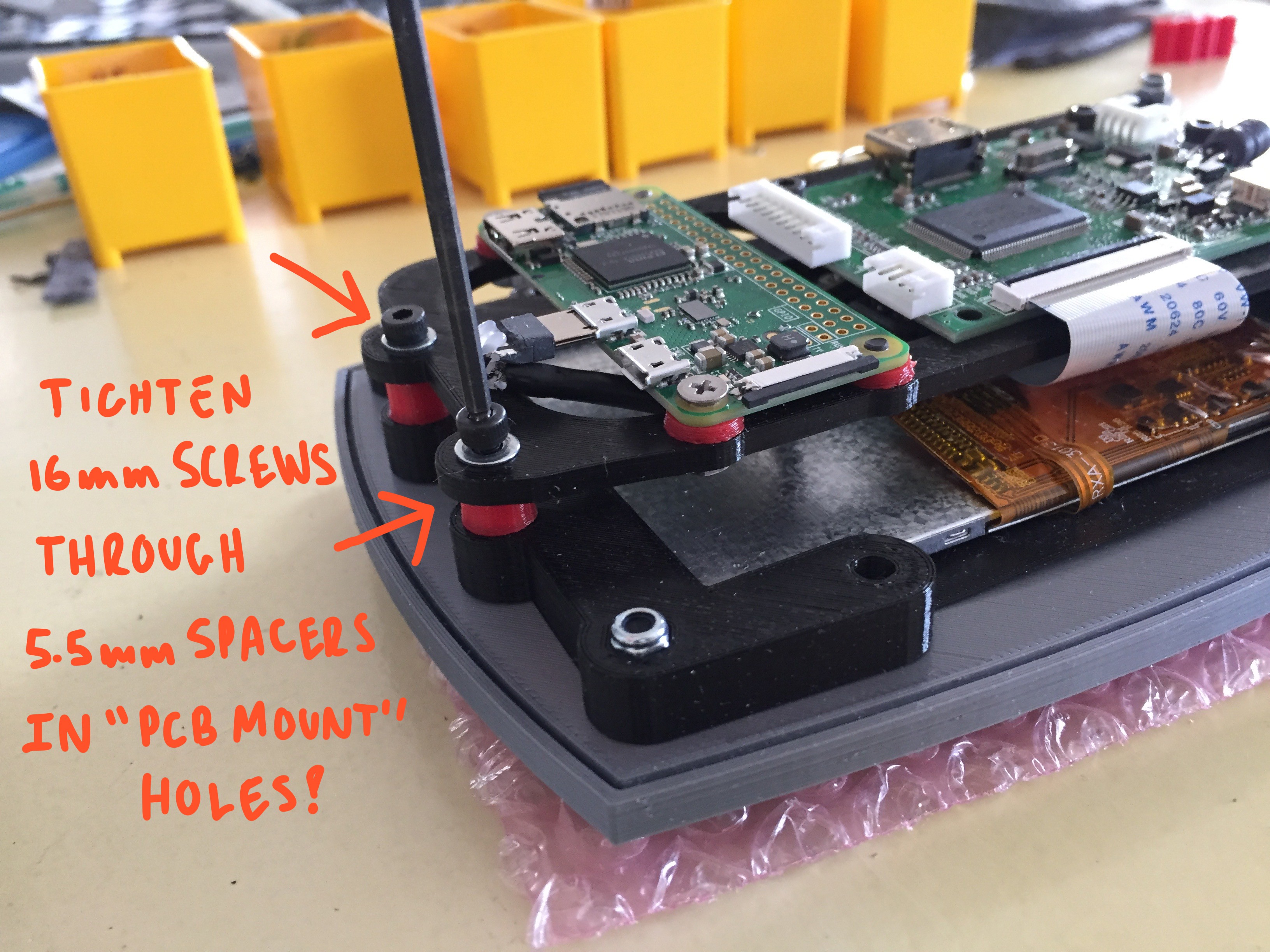
Line up the holes of the "PCB bracket" over the 5.5mm spacers and the receiving holes on the "screen frame", and thread in your 16mm hardware. It will be received by the countersunk nut inside the "screen frame":
![]()
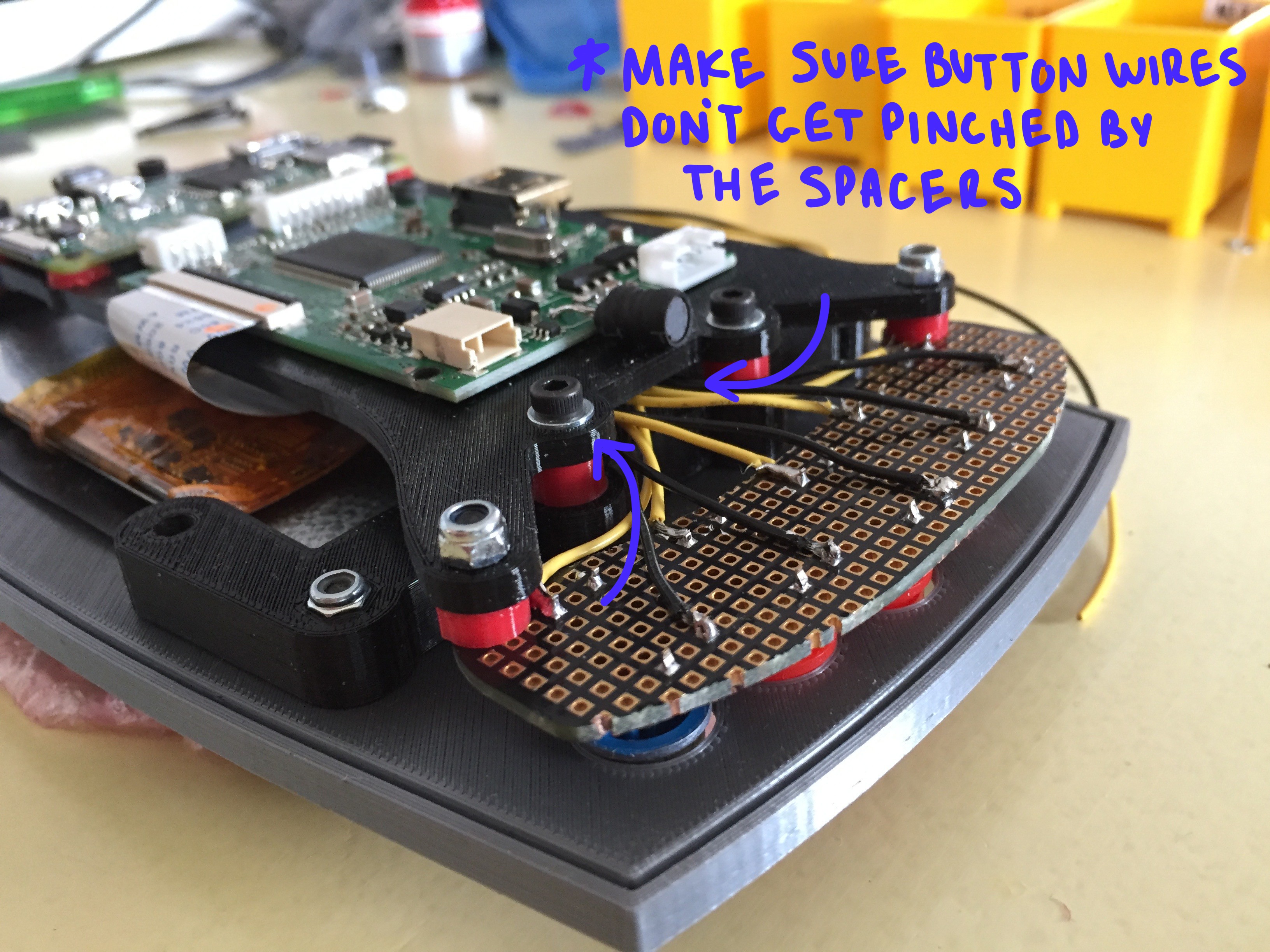
Maker sure that while you are doing this, none of the wires coming off your custom button board are being pinched or twisted strangely:
![]()
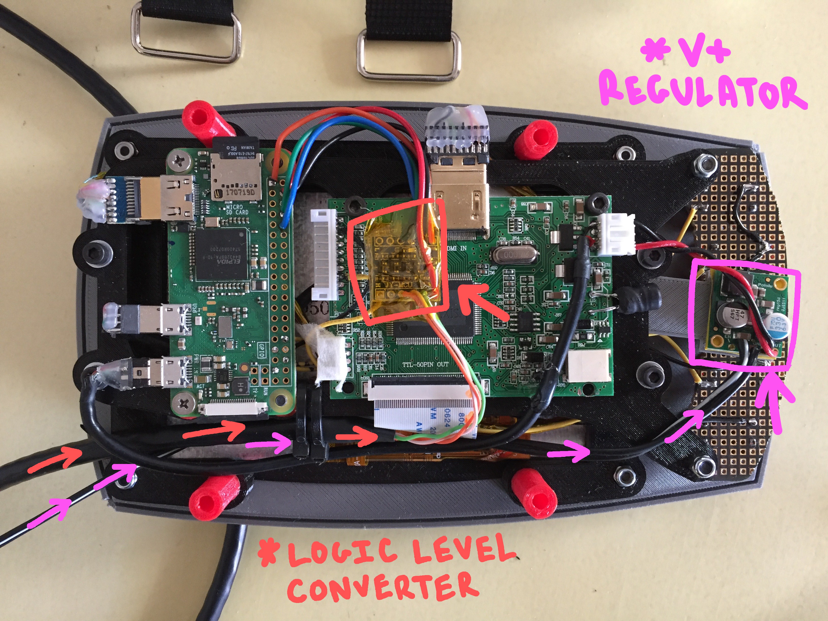
Make sure all of your cables are connected and that everything looks level and parallel. Then lay the assembly face down:
![]()
Your "logic level converter" and your "voltage regulator" should seat roughly in the areas shown above. Be sure to wrap them in protective capton tape so nothing shorts out!
ADD STRAPS TO THE "ARM MOUNT"
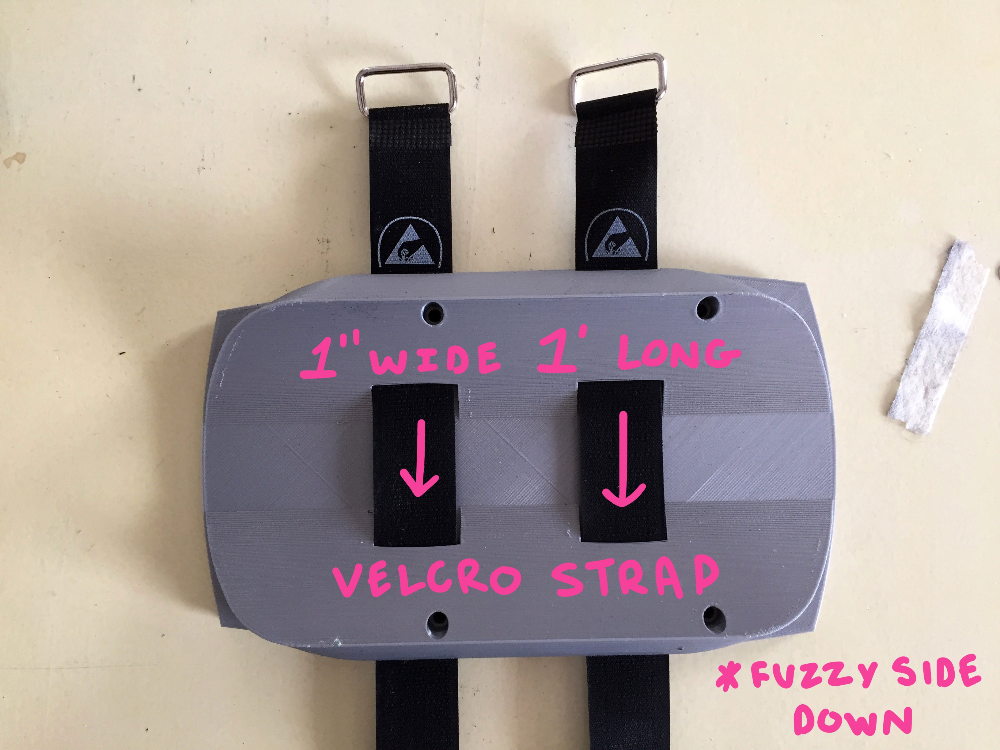
Before you seal everything up, you'll need to do something a little screwy with your velcro straps (something I will likely fix in a later version of this build, but for now... we'll just do the weird work around)
![]()
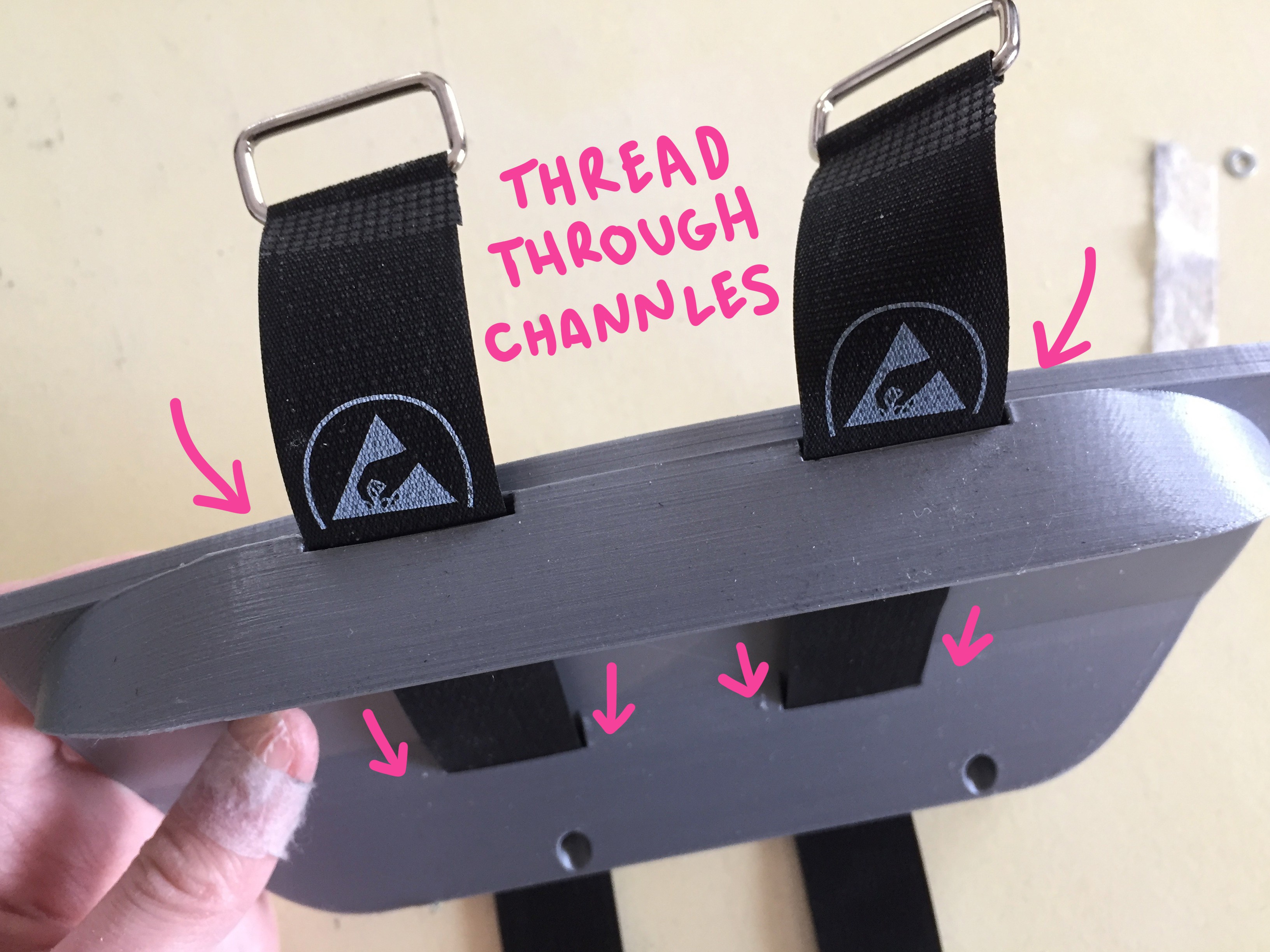
Slide your velcro straps through the flat channels in the "arm capture" piece that you printed.
![]()
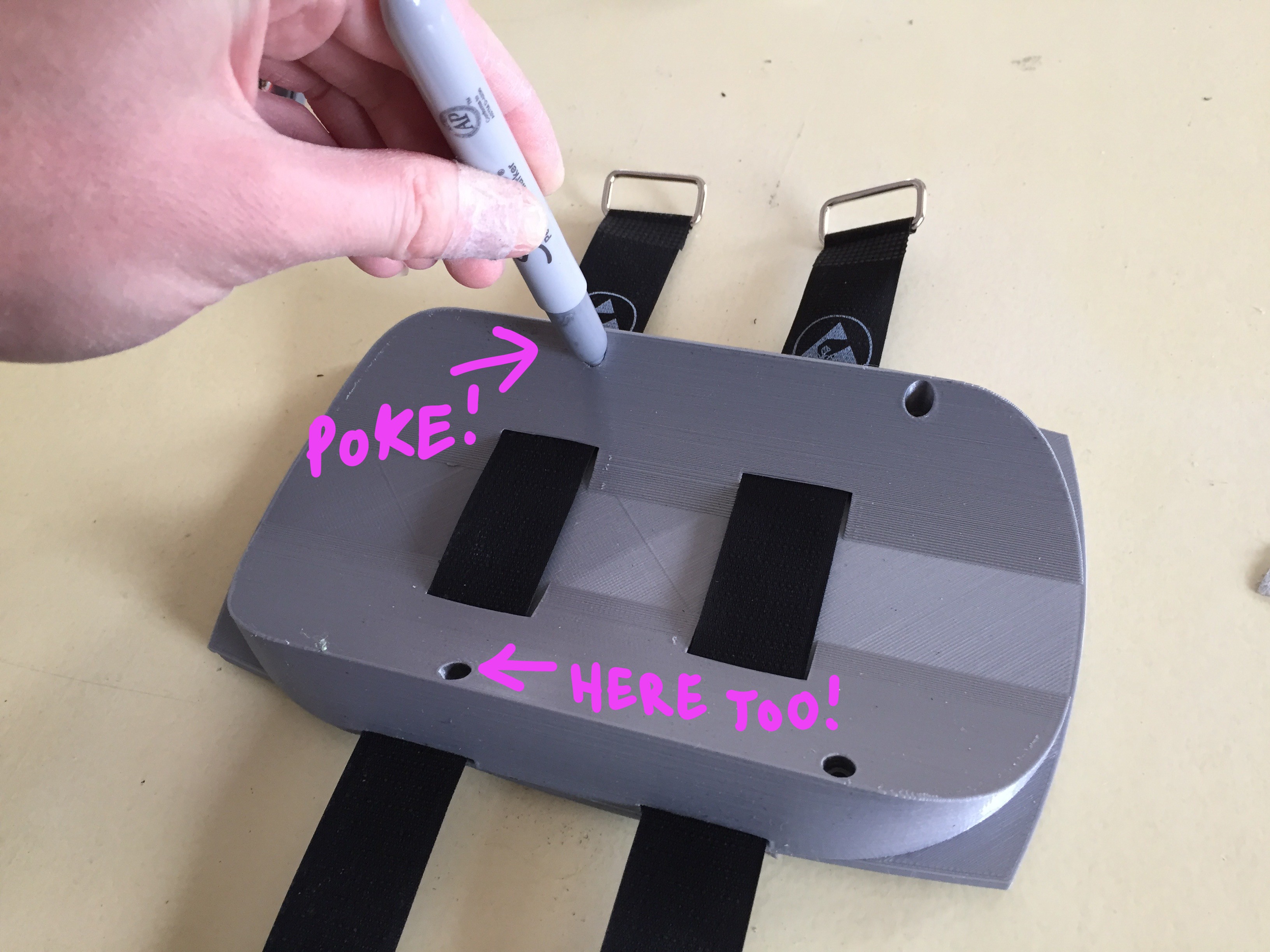
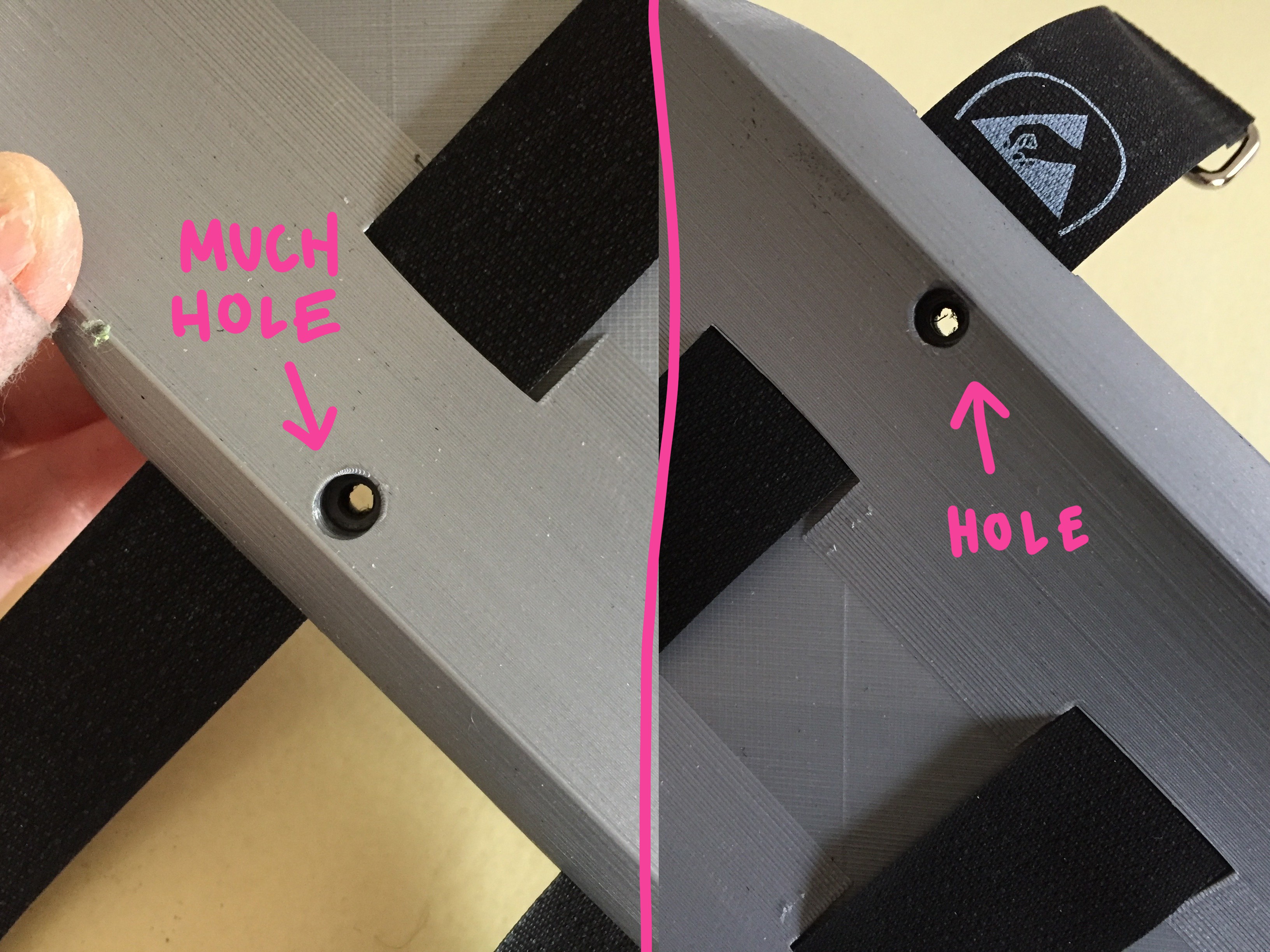
You'll notice one of them has a hole overlapping one of the channels... OOOPS. You will need to pass a piece of hardware through there to seal of the enclosure, so we're going to have to punch some holes in the strap.
Position the straps where they need to be fixed, relative to how they hit the girth of your arm, and then mark where the hole lands with silver sharpie:
![]()
Once marked clearly... use a 4mm punch to piece the velcro strap:
![]()
Yay! Now the hardware can pass through the strap when you're sealing up the enclosure!
There are four remaining holes at this point =O position the 15mm spacers over these holes and use your 35mm hardware to seal the enclosure, screwing from the "arm capture" plate through the spacers, and into the corresponding holes on the "screen frame" (there should be countersunk nylock nuts ready to receive them!).
CLOSE IT UP
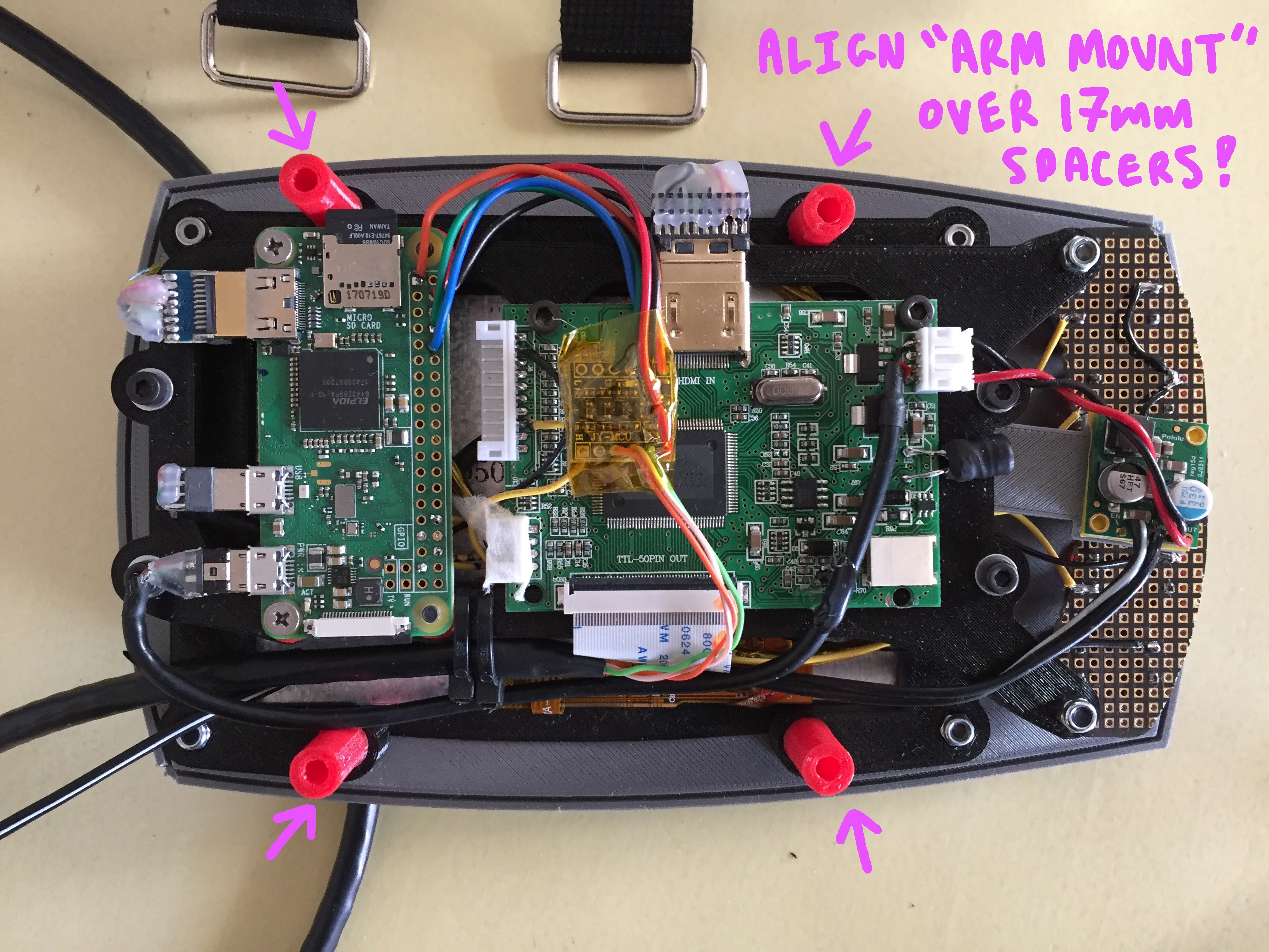
Align the holes of the "arm mount" piece over the remaining 17mm spacers and the remaining holes on the "screen frame":
![]()
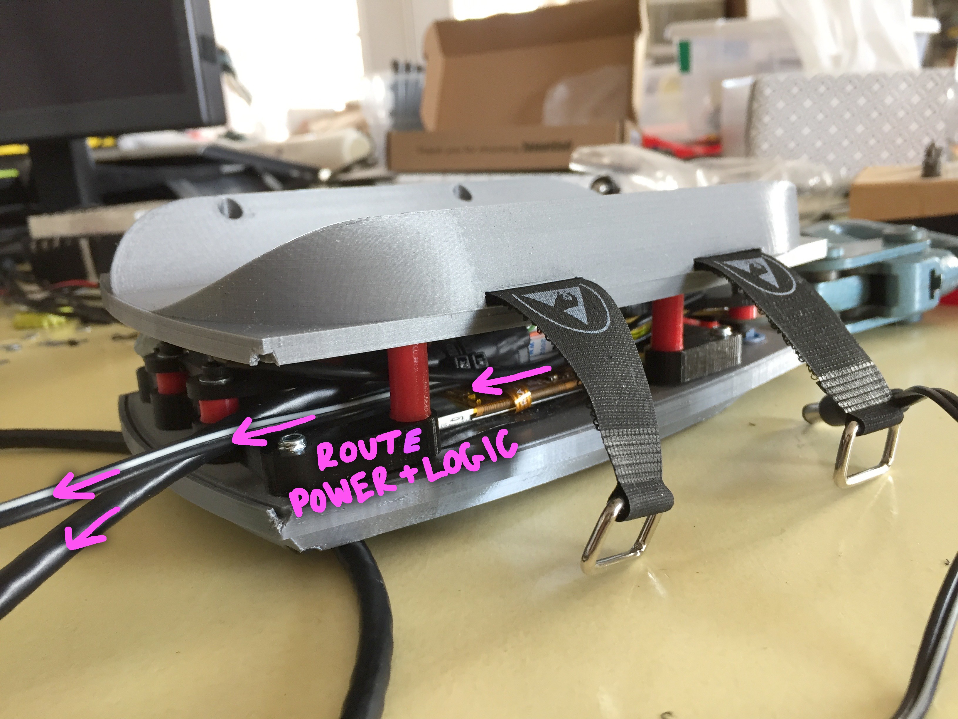
Make sure the cable from the power supply and the CAT5 data line are tucked along the inside of the spacers:
![]()
You will use your 40mm to seal the enclosure. Make sure the top assemble and the "arm mount" sandwich the 17mm spacers and that none of your chords or wires are being pinched as your tighten down the screws into the captured nuts in the "screen frame".
CREATE SOME EDGE
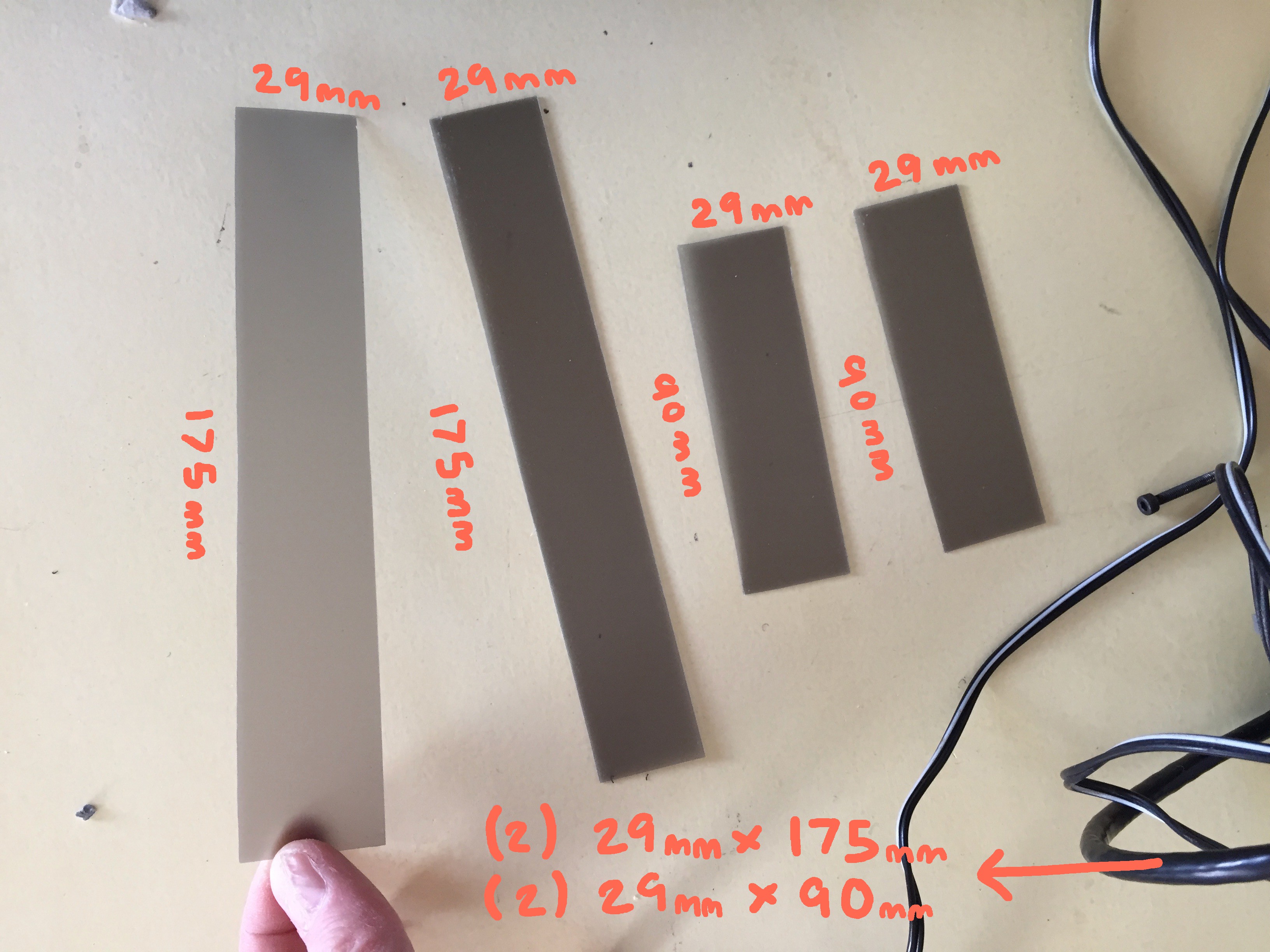
Using some sheet plastic, cut small rectangles in the following dimensions:
![]()
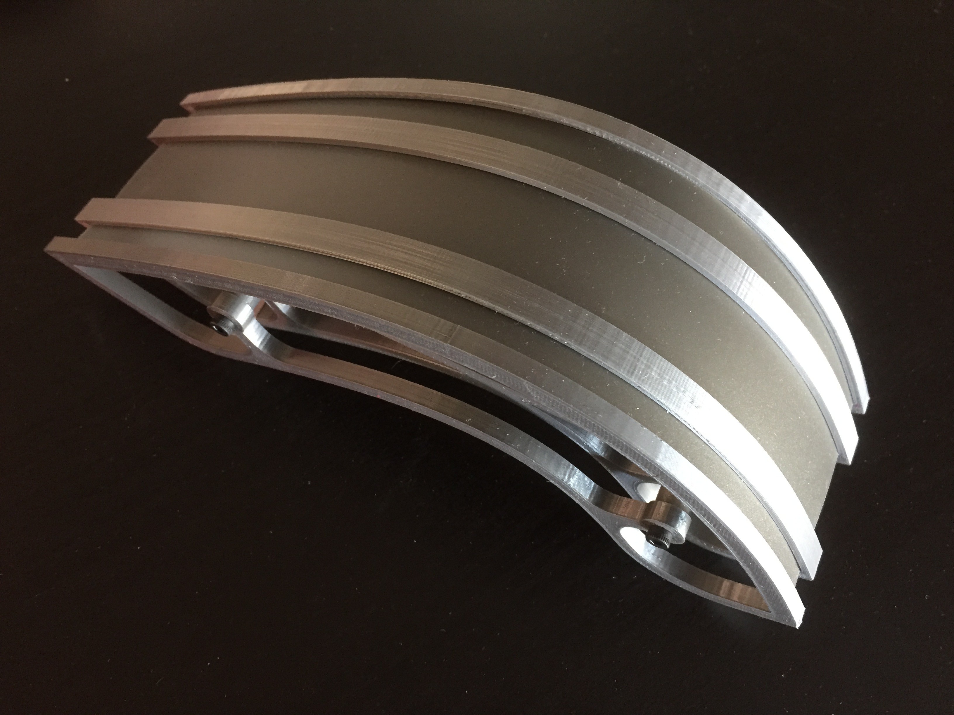
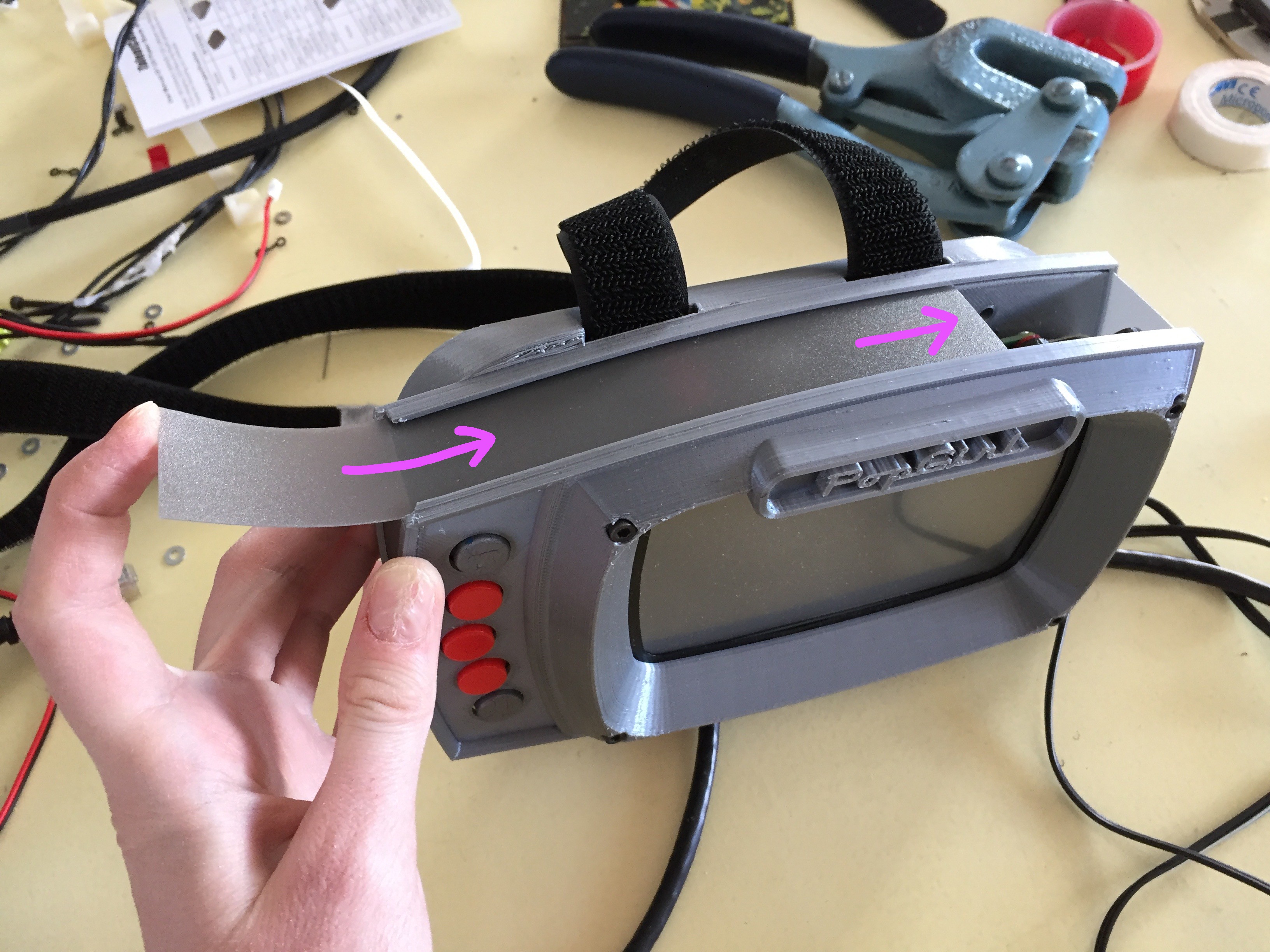
I found some semi-transparent grey sheet that defuses the inside slight from the indicator LEDs on the internal boards quite nicely. Once cut, slide them through the channels along the outside edge of the "face_plate" and the "arm_mount":
![]()
The right side of the enclosure wall should have a hole open for the CAT5 cable to pass through.
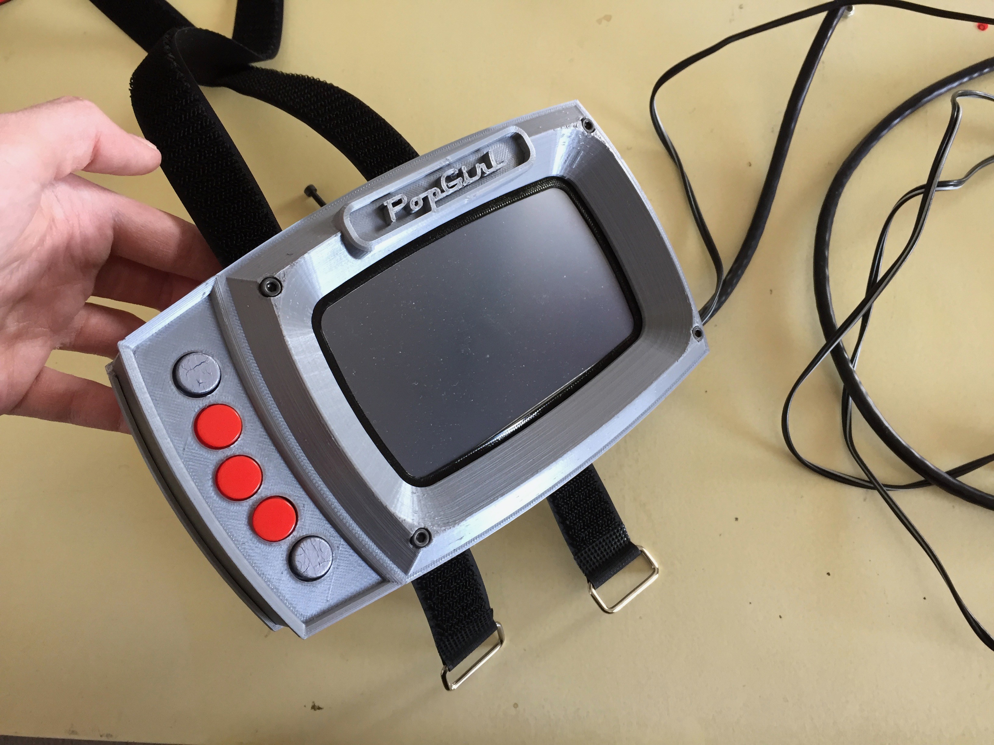
Once this finishing touch is added... you are ddddoooooonnnnneee.
![]()
The final step is to get the software running on the Pi. So, maybe don't close the thing up just yet. =P
![]()
is glorious!
![]()
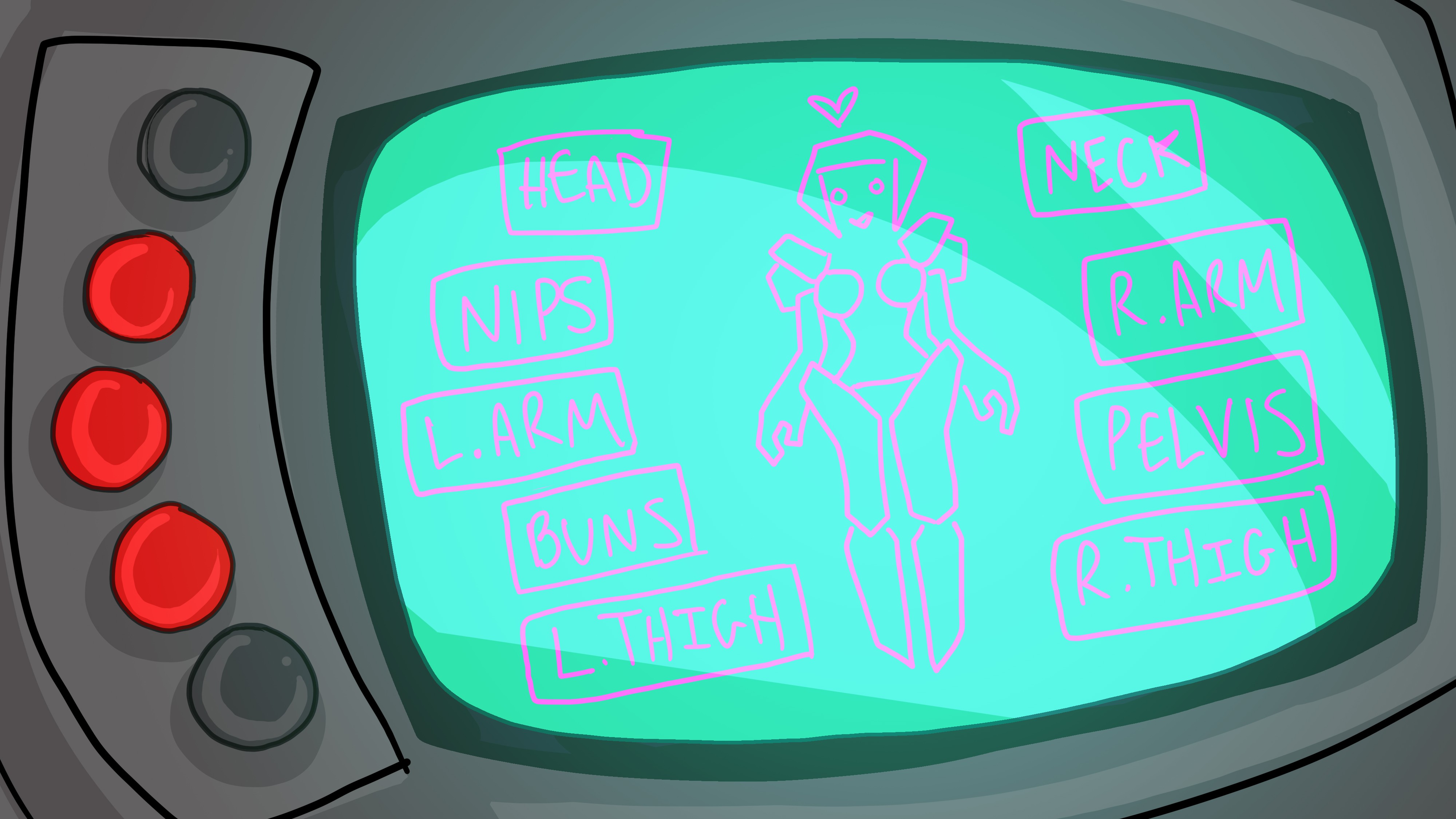
The software instructions will come shortly! Until then- enjoy my wiggly concept sketch of the UI layout!
![]()
-
The Meat and Potatoes of SHE BON
10/04/2018 at 17:05 • 0 comments![]()
I'm creating a series of wearable tech for use throughout my body, which will sense and indicate different aspects of my physical status! While my personal reason for developing this technology is intimate in nature, the system I'm creating could easily serve a number of purposes in other contexts as well.
- if you have ever wanted to create a wearable device that senses information from your body
- wish to create a wearable that expresses something about your immediate state
- have a need to network multiple unique wearable projects together
- would like to visualize data received from sensors imbedded in devices you've made
...then SHE BON might help!
I'm going through lengths to document my progress on the development of this platform, so that it can serve someone else as just that: a platform from which you can build upon for a countless number or reasons.
---------- more ----------THE HUMAN-COMPUTER INTERFACE
The "PULSE PACK": a wearable breakout board "brain" used for networking other wearables!
the "POPgirl": a status indicator worn on the arm with a screen interface that visualizes the data received from the devices plugged into the PULSE PACK.
You could think of the two as computer tower, and computer monitor:
![]()
The idea is that you can plug up to (9) devices into the ports along the outside of the PULSE PACK. The devices communicate with the brain circuit board inside, which I just call the "pulse".
While I chose to make a heart-shaped backpack as the enclosure for the brain board, you could do something entirely different all together (and just incase you DO want to make a heart-shaped backpack, the instructions on how to do so can be found on the Pulse Pack Instruction page!)
The POPgirl reports a visualization of the data received by the "pulse" brain:
![]()
Similarly, I chose to make my user interface mount onto my arm- but I encourage you to use the same guts in whatever form factor you like. If you do want to build a wearable arm-mounted enclosure, I'm working on compiling some visual instructions for that too (right now in fact!).
Very soon, I hope to have instructions for the following documented:
- How to interface things you've made to the main brain, the "Pulse" board
- How to build an enclosure for the brain
- How to build the display user interface
- How to hook something up to the display user interface
Right now, I'm currently working on getting the UI up and running. I'm also trying to finish up a proper enclosure to cram everything into :3
ALSO, since only three wearable systems exist so far (for the nips, pelvis, and thighs), I'm going to create a bank of potentiometers to act as a stand-ins for the rest of my sensor values. This way, when I demo the system in use at SuperCON next month, there won't be any empty ports on the backpack.
This means... if you twist one of the knobs on my "stand-in bank", it will act as a sensor and change the input value on the screen of the POPgirl.
Here is a taste of what I've been developing this week...
![]()
I'm busy printing all the pieces, and taking the pictures... so I can make good instructions for the enclosure build <3
![]()
![]()
...and Mark (my code hobbit) is working on the Java application that will run on the Raspberry Pi screen thing I picked up from adafruit. Here are the graphics I'm currently designing for the UI:
![]()
more to come soon <3
-
Hip Winches
09/25/2018 at 22:23 • 1 commentMy goal this past week was to create a belt of hip-mounted winches!
Why, you ask? In short, my next peripheral for SHE BON require I scheme up a mechanism that is able to create thigh gap between my legs by pulling apart the meat of my buns. You can read more about this on my introductory post about the HOT SPOT.
For this cause, I decided to use a pulley/tendon system, which yanks at a long strip of kevlar rope adhered at a diagonal bias across the plane of my flesh just below my buns.
- To do this, I first had to calculate how strong my motors would need to be in order to supply enough torque for the job.
- Second, I'd have to mount these said motors at the right angle on my fleshy body, however solidly enough so that they stay put relative to the pieces being tugged.
The later is as challenging as it sounds. I'm running into much the same issues as with my propellor pasties: the human body is a terrible anchor point for mechanical components... *sigh*
---------- more ----------CALCULATING TORQUE!
![]()
At some point earlier this summer, I knew I would need some torquey motors strong enough to lift the dense meat of my body against gravity. I also knew, I didn't want anything too terribly powerful, as I don't wish to have my butt literally ripped apart either.
Luckily, I had a friend who is somewhat of a mechanical engineer. NoodleFeet's shape daddy assumed the roll of "butt technician" for a night, and helped me rig up a test environment for the purpose of calculating how many ounce-inches of torque it would take to do the task I required.
I am currently producing a video that explains this process a bit more in depth; in short it has to do with springs, calipers, and weights. =P
Once all was said and done, I learned some fun numbers I never thought I'd know. It takes 9.5 pounds of raw force to pull my bun up and apart. This comes out to 150 ounce inches of torque. YAY
A HIP HUGGING BELT
![]()
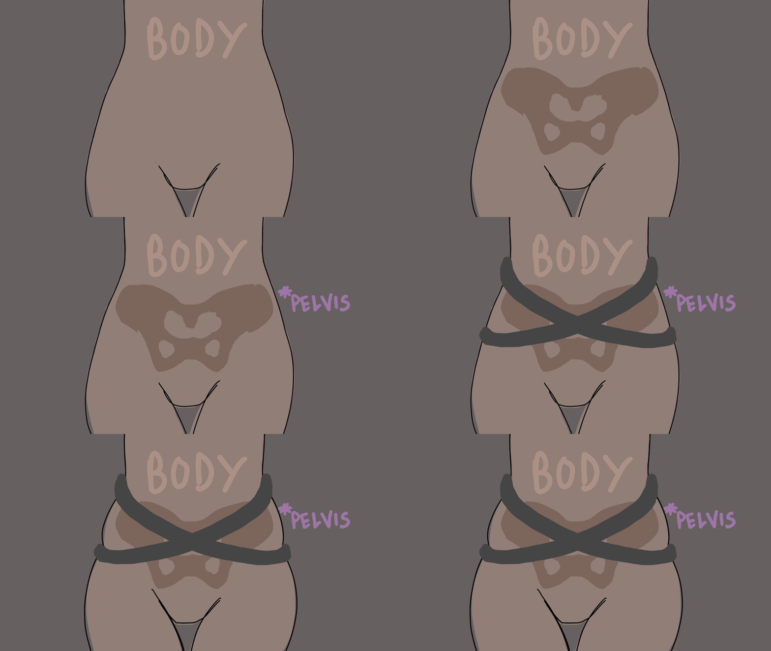
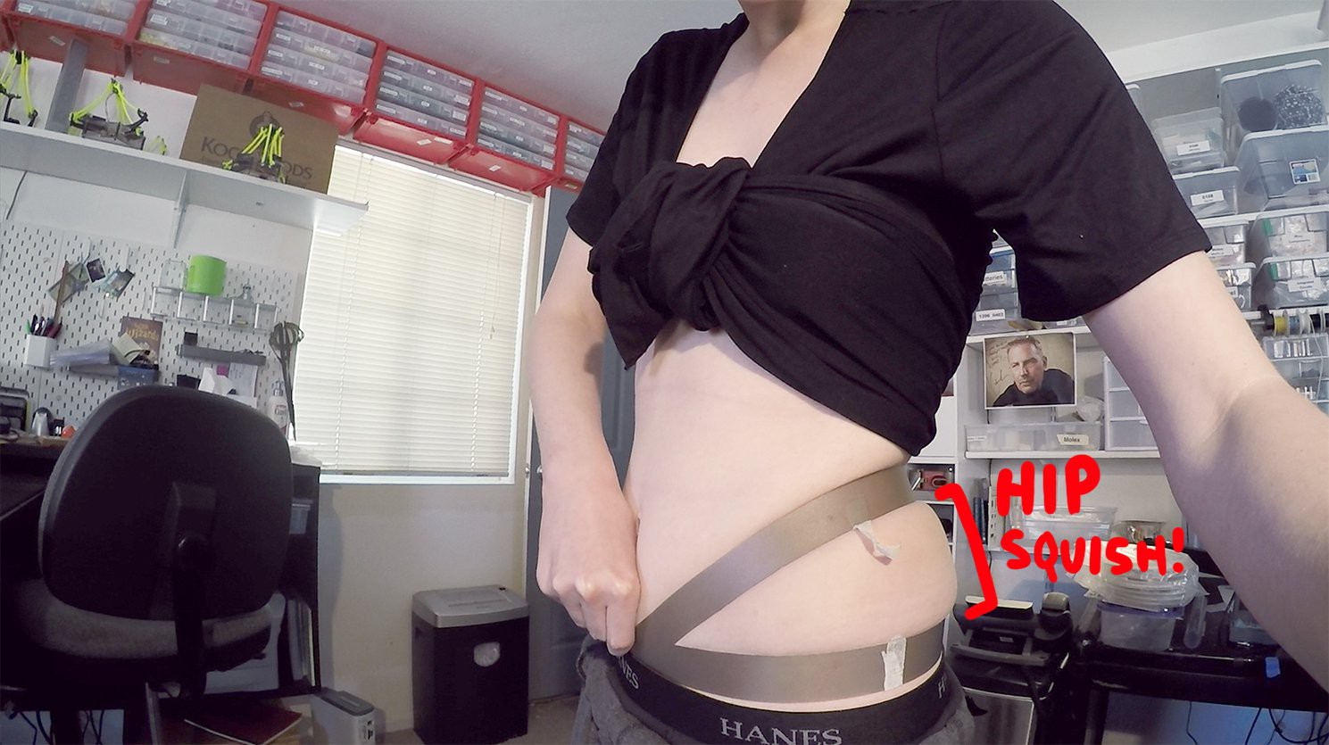
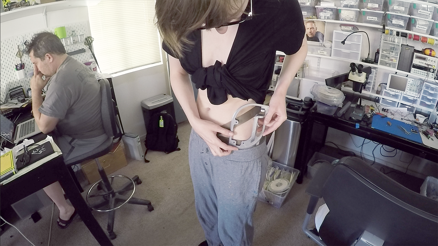
I decided early on to fashion some sort of "belt" that leverages the relative static position of my pelvis bone...since alignment and solid mounting are key.
![]()
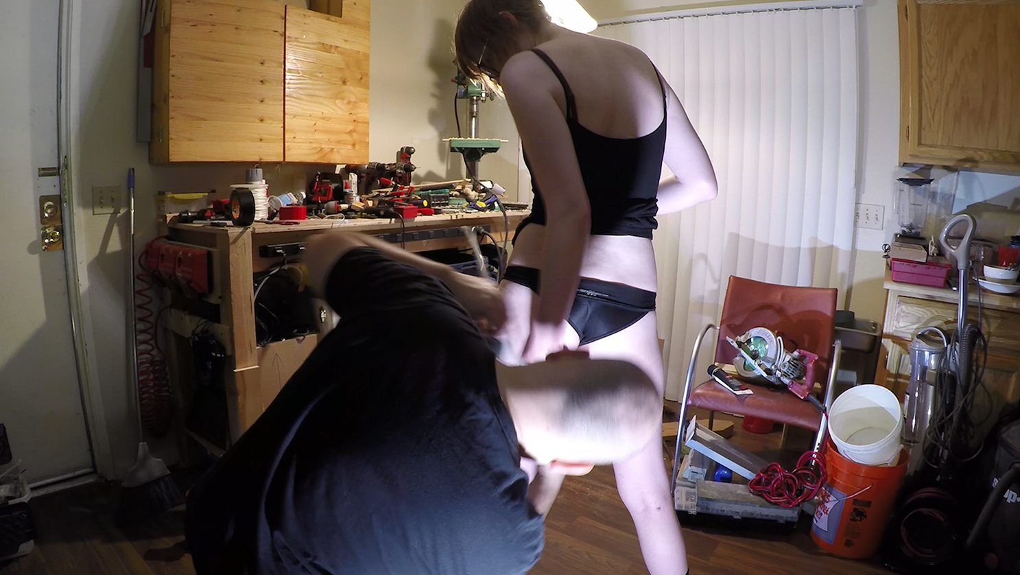
I cross-crossed two thin strips of sheet ABS plastic across the front of my tummy, so that the strips would ride just above and below where my hips protrude. Once tightened, the bone is sandwiched tightly, and the belt can't move up or down very much!
MECHA HIP WINGS
![]()
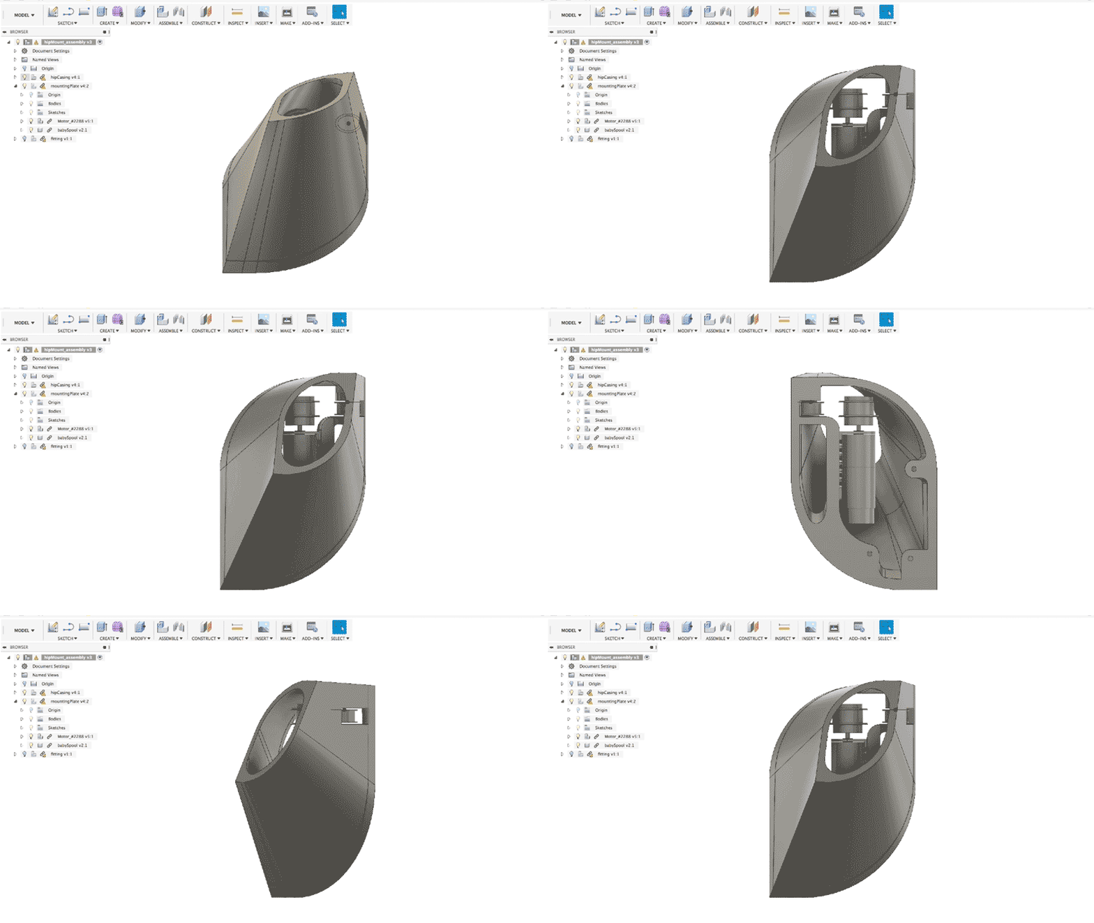
The next step was to create something in CAD that would bridge the winch to the belt, like a mounting bracket.
Since the belt leverages the relative static position of my hips, the winches would need to mount somewhere along this area.
It made sense to me that the frame-bracket aught to cup the protruding hip bone, with the mounting points somewhere opposite from the point of pull.
If I take this one step further and consider aesthetics regarding the full ensemble, then it also made equal sense that this hip mounted motor be housed in some sort of wing or fin... star and shabby, much a like a fundamental or mech:
![]()
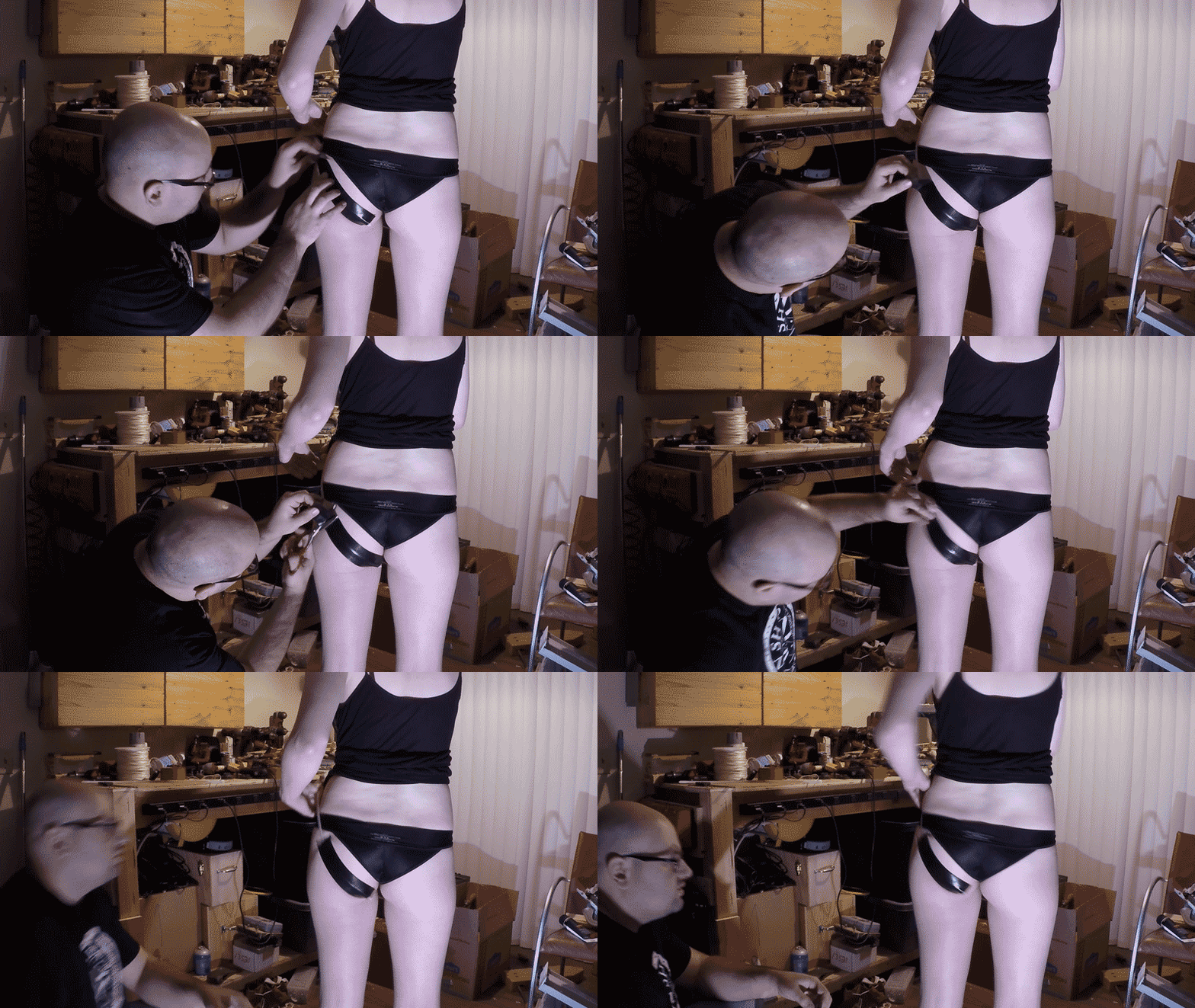
The next step is to work out how the cable or tendon will adhere to my thighs. Originally I was thinking of using some sort of liquid bandage or medical adhesive to do the trick... but seeing as how the quick and easy (also affordable) gorilla tape also proved to be effective, I will use it in the beginning- for now.
I will likely rig up a test environment for the whole system sometime this week. Hopefully I don't tear anything, or burn out the motors =P
Once it's in a somewhat working state, you know a video update will follow explaining the outcome.
until then, cheers and happy October 1st!!! Go get those pumpkin doughnuts.
-Sarah
-
Goals For the Next 30 Days!
09/22/2018 at 00:47 • 0 comments![]()
FIRST OF ALL, SHE BON in a finalist in the Human Computer Interface category for the HackaDay Prize!! This is so very exciting!! =D
This means two things: ( 1 ) I get a little bit of money as a result to spend on materials and parts ( 2 ) I have a TON of work to do in the next month!
As a refresh on the memory, the SHEBON project will involve the creation of (9) unique wearable augments! Even though I intend to complete them all in time, I can only expect to make so much before the HackaDay Prize judgement period begins on October 22nd.
It seems like a good time to hash out my goals before then, and also go over what I am preparing for open source documentation!
![]()
As much as I'd like to have the entire project ready to prance in by the middle of next month, I don't have enough humanly power and waking hours to pull that off. I will try my hardest to have a decent sampling to show... say... a full outfit. Here is a list of the sub-systems I will shoot have have developed by the judgement period:
- nips (propellor pasties)
- pelvis (beat box)
- buns (spank skirt)
- thighs (hot spot)
---------- more ----------What this means: I will work towards having the sensors that are imbedded in the augments listed above, communicating input values to the PULSE board (mother brain of the project), so that it can send those values to the graphical interface worn on the arm.
This means part of the next month will involve preparing the GUI that will be displayed on the touch sensitive screen... which will be housed in an enclosure for the forearm. (think of it as a pip boy for your arousal!)
![]()
THE OPEN SOURCE PART:
It goes without saying, the individual wearable augments themselves are kinda personal! They are utilities calibrated to serve my body specifically. Their various forms are based on my own quirks, silliness, and personal narrative… so it doesn’t make much sense to open source them specifically (I doubt anyone would find the need for a whispering crotch salmon anyway…)
The part which will be available for replication and iteration will be the literal heart of the project responsible for receiving, orchestrating, and logging the data collected from the wearable subsystems. Additionally, I'll provide documentation, code, and instructions for the wearable GUI that functions as an active status indicator !
Before October 22nd (when the judging period for the HackaDay prize begins), I will document as much of my progress as possible regarding how to utilize the core system for your own personal projects! That way, if you choose to make your own “BON”, you’ll have the brain and UI as a base to start with!
![]()
IF YOU WERE A KINKY GUNDAM, WHAT WOULD BE YOUR FINAL FORM?
Yes. I submitted this project to the HackaDay Prize... which is first and foremost about having an impact on the world by bringing an invention to life and sharing it with others.
While I realize this project does not qualify as a traditional utility, the concept embodies and confronts an aspect of human nature that I would like to change for the better. I think this can be achieved through personal exploration, and discussion... and I believe producing personalized technology can act as the ultimate catalyst for such discussion!
I hope by creating these personalized body augments for myself, I encourage you and others to consider what you'd make for yourself if tasked with the challenge.
Even if it isn't intimate in nature, how would you use technology to communicate with others in a personally expressive way?
![]()
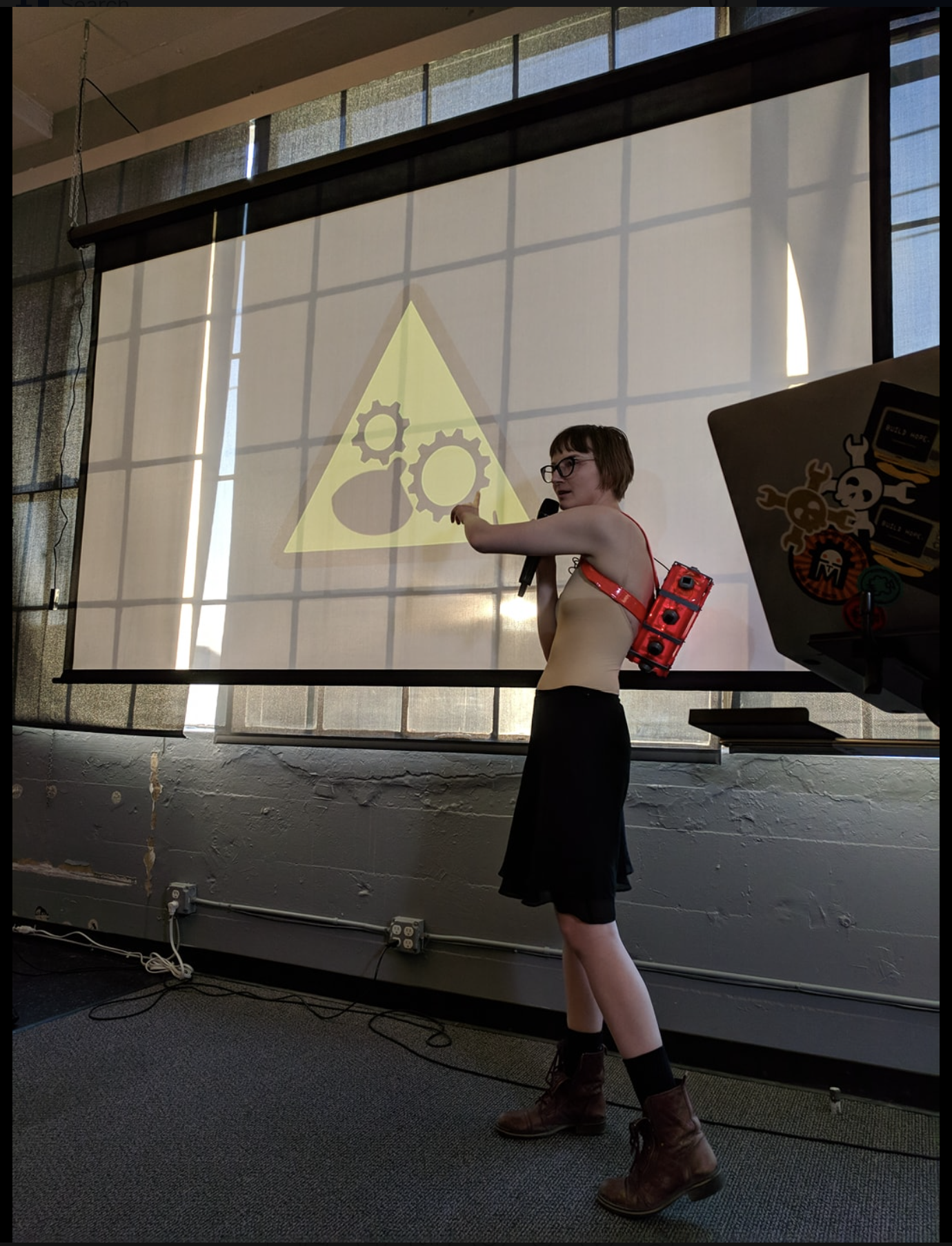
I'M GIVING A TALK ABOUT ALL OF THIS AT SUPERCON!
That's right... my talk was accepted! So, I'll be simultaneously preparing the skirt that spanks, the belt that lifts and separates the buns, the whispering crotch salmon, and the propellor pasties for demo!! This is so exciting!! =D
Currently this week I have been working on constructing a corset... girdle... belt?? It needs to be worn around my core and act as a strong enough mounting point for the pulling force of two winches...I'm making winch hips.
-
Away for August! (but not lost!)
08/31/2018 at 00:36 • 0 commentsHey everyone! I realize I teased with two new enticing project challenges: the "HOT SPOT" and the "SPANK SKIRT" and then went quiet all month long!
The reason is that I have a very important exhibition coming up at the beginning of September involving my robot offspring, NoodleFeet, and needed to focus all of my parental energy into readying them for the big day!
I promise to get back to SHE BON soon. I have an update on the HOT SPOT in progress right now, and am well on my way to getting both peripherals up and working (to some relative degree for a first iteration lol).
Until I return, you can check out what I've been preparing for on my youtube channel : ROBOHEMIAN! (I'll be in Linz for the ARS Electronica festival)!
Here is a little bit of the fun I had a few weeks ago while calculating how much torque is necessary to spread my buns. :3
![]()
-
Talking About SHE BON @ HDDG 32
07/29/2018 at 22:02 • 0 commentsTwo weeks ago I gave a talk about SHE BON at one of Supply Frame's HDDG Meetups in San Francisco!
![]()
This was super exciting for me, as it was the first time I spoke publicly about the project. I really had no idea how it would go over with humans outside my immediate social bubble- and I was pleased with the amount of feedback I received from everyone at the bar afterwards.
---------- more ----------![]()
Sitting on the couch in the dark and moody pub, I had my wares on display all over their drink table. It was interesting to witness the reactions of the hardware developers of SF. Observation is sometimes the best form of critique. Not everyone keys in on the why, but everyone most certainly is engaged by the content and the challenge I've placed before myself.
![]()
This was also the night I met a fellow sensuality hacker, @qDot, in person. I'm new to this other world of sex-tech and hardware creation/hacking, so it was helpful and assuring to meet a veteran who had wisdom to pass onto me about the path I've started walking.
It's still summer and there is plenty to do before SuperCon, so I best get back to that!
(Also, this was probably the first talk I've given where I wasn't scared out of my undies.) cheers to personal growth.
Huge thanks to @Sophi Kravitz for making this happen, and for seeing the value in what I do <3
Relavant Followup article is here: https://medium.com/supplyframe-hardware/hddg-32-stimulating-communication-through-titillating-wearables-1af7876eec4d
 Sarah Petkus

