mmca
mmca-
Weaponized Blinky Ball at Defcon 26
08/14/2018 at 22:23 • 0 comments![]()
Blinky Ball with TwinkleTwinkie's SAO 6
Survived another Defcon!
This year we brought along the Blinky Ball, for a little show and tell.
While there, we installed the WiNX (Wi-Fi attack-defense) suite of tools on the ball (https://www.hackerarsenal.com/products/winx)
We got a couple nibbles on the Deception setting, but we hope that was just people fooling around and not actually trying to connect to unknown random access point at Defcon.
No one will probably ever install an Wifi scanner/sniffer, honey pot or a custom captive portal on their Blinky Ball. But I am happy to report that if you want to, you can.
We have also come up with an answer to, "What is that?"
The answer we most often gave was, "It is something that sits on a desk or shelf and gives off light.... It's a lamp."
- It's lamp that has 384 RGB light elements all individually addressable.
- It's a lamp that has a 9 DoF IMU so it knows which way it is pointing, how fast it is accelerating and which direction is North.
- It's a lamp that has a temperature sensor.
- It's a lamp that has a gesture sensor so it knows which way you are flailing your hands.
- It's a lamp that has a light senor so it can auto adjust brightness.
- It's a lamp that has a color sensor so it knows the ambient color (you can also bounce back the Blinky Ball color to it self, to self calibrate.)
- It's a lamp with a digital mic so it can react to sounds.
- It's a lamp with a 32-bit DAC (and headphone jack) so you can stream music.
- It's a lamp with a voice assistant (you need to supply a speaker and an Amazon account).
- It's a lamp that has Wifi and Bluetooth so when you don't want to wave your hands at it you can use your phone or computer to control it.
- It's a lamp that has a 4000mAh rechargeable lithium cell so it can do all of the above when it is away from its desk or shelf.
In short, it is what happens when hackers design a lamp.
-
Comedy of Errors
07/27/2018 at 21:22 • 2 commentsI got the boards back 2 weeks ago, but ran in to all sort of issues. I decided to use a board house I hadn't used in a while and that caused some problems and there was also just some real crazy goofs on my part.![]()
I like to build new boards by hand, one section at a time to make sure everything works like it is supposed to, in this case that did not help too much. Here are some of the fun mistakes I made on this board.
![]()
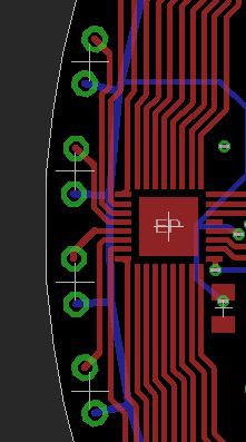
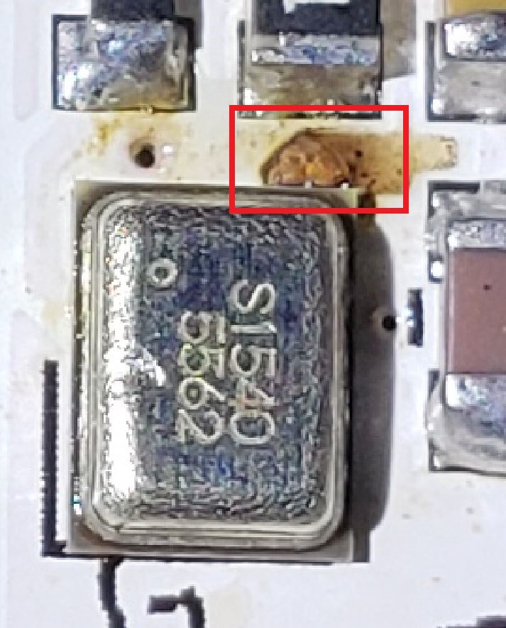
I forgot to change the isolation in the GND pour and ended up with very tight clearances. In this case 1.5A of 3v3 was right next to a small chip in the solder mask, a solder ball found it way to that gap it blew it out. If I had had allowed a little more isolation in the GND plane, that area would have been clear and the chip in the solder mask would not have had any affect. I fixed it with a little bit of nail polish, and this particular board is fine now.
![]()
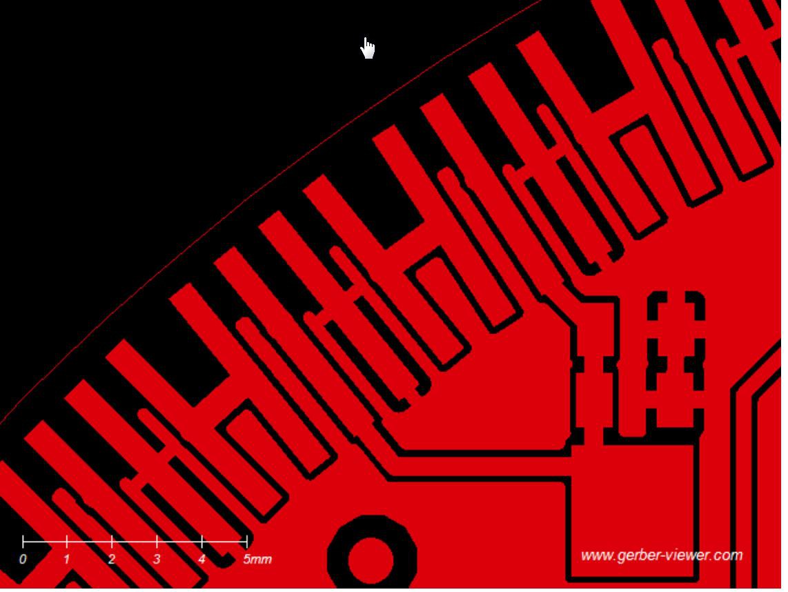
Here I isolated a little island of GND. I don't even have a copy of the board file with this error, so I must have fixed it in the general course of tidying up the board. Unfortunately it got sent to the board house, so the prototype has 15 little bits of Kynar wire.
![]()
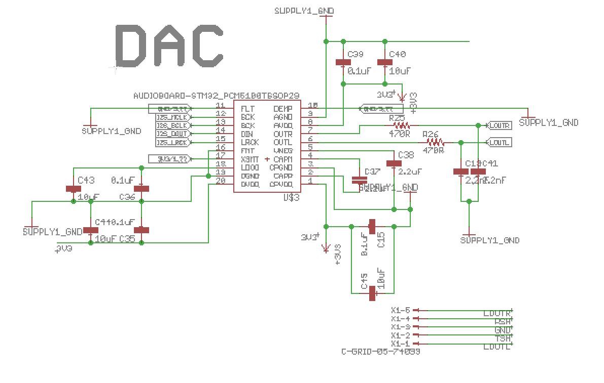
This one is just nuts. The DAC IC was throwing a design rule check error (DRC), so in the course of trying to fix the problem I deleted the part in the schematic, rebuilt the part from scratch and put it back in the schematic. There was still an DRC error and I went about looking for other possible solutions (turns out I had 'highspeed' checked). But the problem was when I replaced the part in the schematic, I put it back rotated 180 degrees. So when I built the board the 3v3 rail was pulled down to 3.24v... odd but not something I was really worried about until the DAC IC heated up to untouchable temps.
![]()
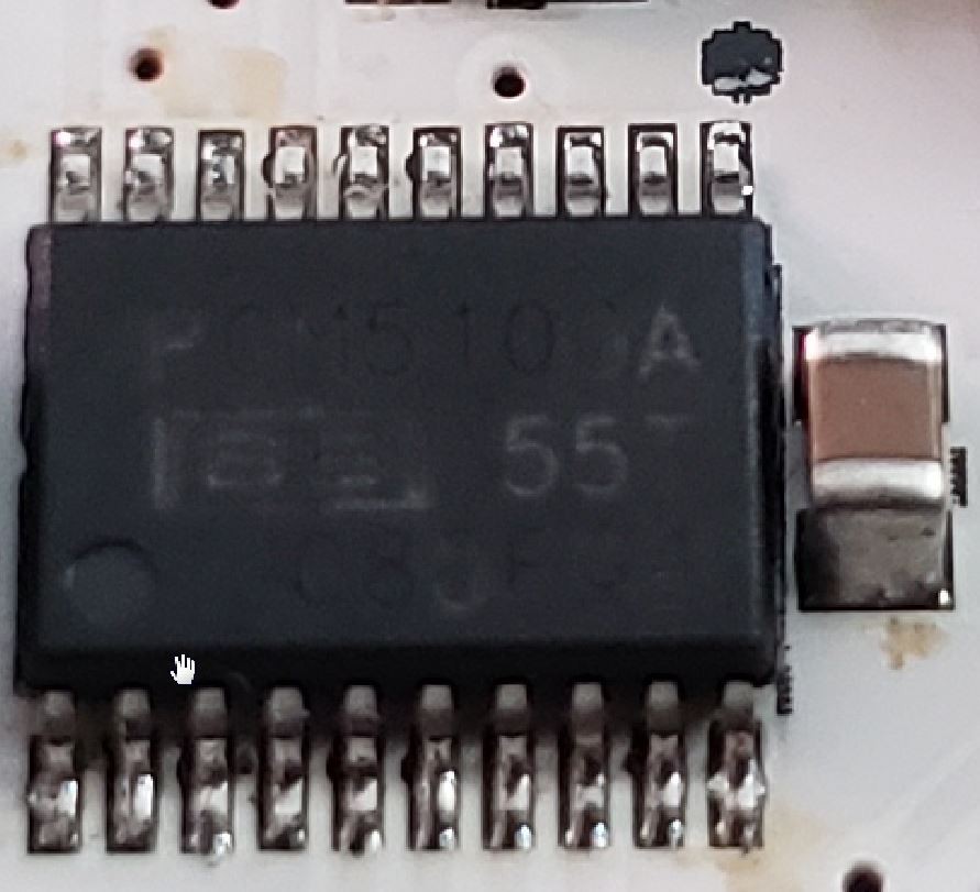
Luckily the board is still usable if I rotate the IC on the board. (Note the pin one mark and the dot on the IC, fun.)
This was also the first time I put a USB-Serial interface on the ball, up to now it has been an off board adapter. When I was testing just a single slice, everything worked great. Once the ball was completely built and I plugged in the ball to my computer, it blew the USB sub systems and reset my monitor (that was a little scary). It seems my computer will let a device try to pull 2.6A from the USB port and then blow a fuse. After a reboot, all was well with the computer. As for the ball, it now has a button that can be pressed at boot to suppress the LEDs, so you can plug it in to your computer for programming. Yay! (If anyone out there knows of a USB hub that does 2.4A and data at the same time please let me know.)
So that was a couple days of frustrating troubleshooting, but as you can see in the video above, it all works, so I'm pretty happy with that.
If you happen to be at Defcon 26, drop by the Tamper Evident Village, I will have a blinky ball there for your viewing pleasure.
-
A small video break
06/27/2018 at 18:47 • 0 commentsA small video intermission as we wait for PCBs to come back from board house.
-
Evolution of the Main Slice
06/27/2018 at 18:42 • 0 commentsIn our first Blinky Ball all 16 slices where the same PCB. You would build out the main slice with MCU, Bluetooth, battery charger and the other slices just got LEDs and a driver chip. I was super happy with this and was constantly patting myself on the back about it.
But as we moved to the RGB ball and especially when we got to the battery powered RGB ball all the slices started to get specialized.
![]()
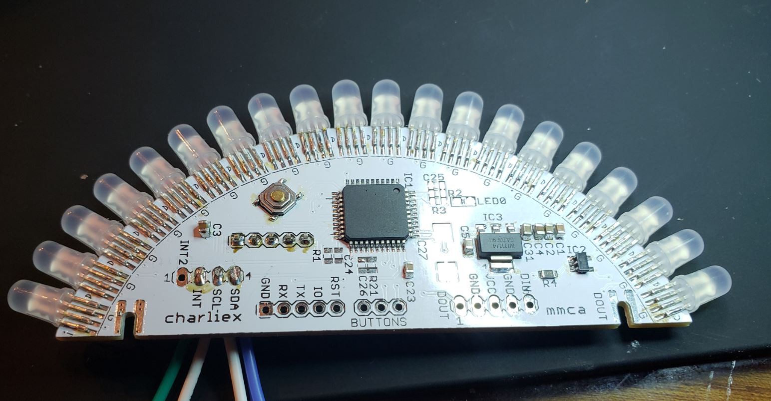
This is the driver slice with Cypress PSOC4 and an logic level shift (the PSOC is a 3v3 device and the LEDs expect 5v signal). In this version all the colors/patterns are done in PSOC4. In the next version the heaving lifting will be offloaded to another processor.
![]()
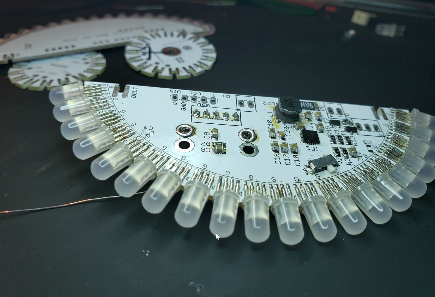
This is the power slice, It takes USB power and charges the 18650 and boosts the 3.7v of the battery up to 5v. We are using the IP5209, a highly integrated power management SoC, it isn't the best documented chip, but we are figuring out all its little oddities. It is a great little chip, you add a couple caps, resistors and an inductor... good to go. Unfortunately there is no easy way to disconnect the 5V from the circuit, so the next revision has bits for that.
![]()
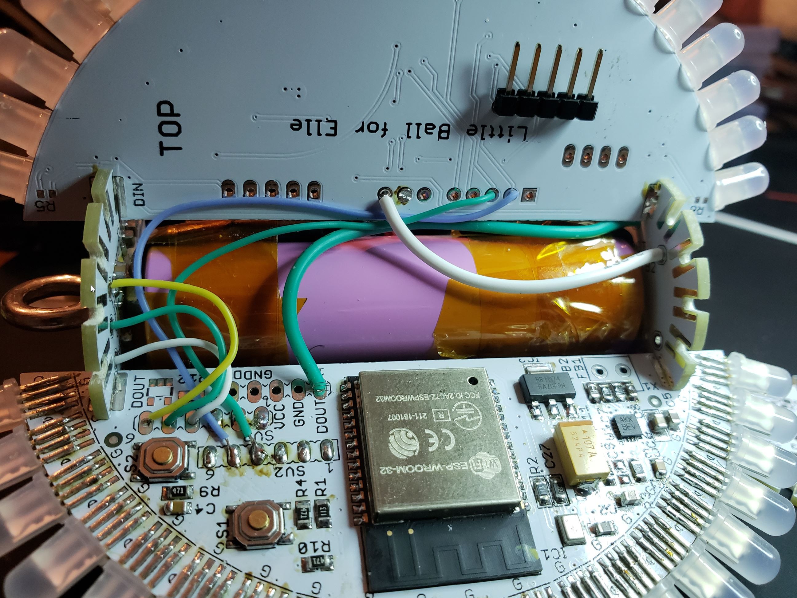
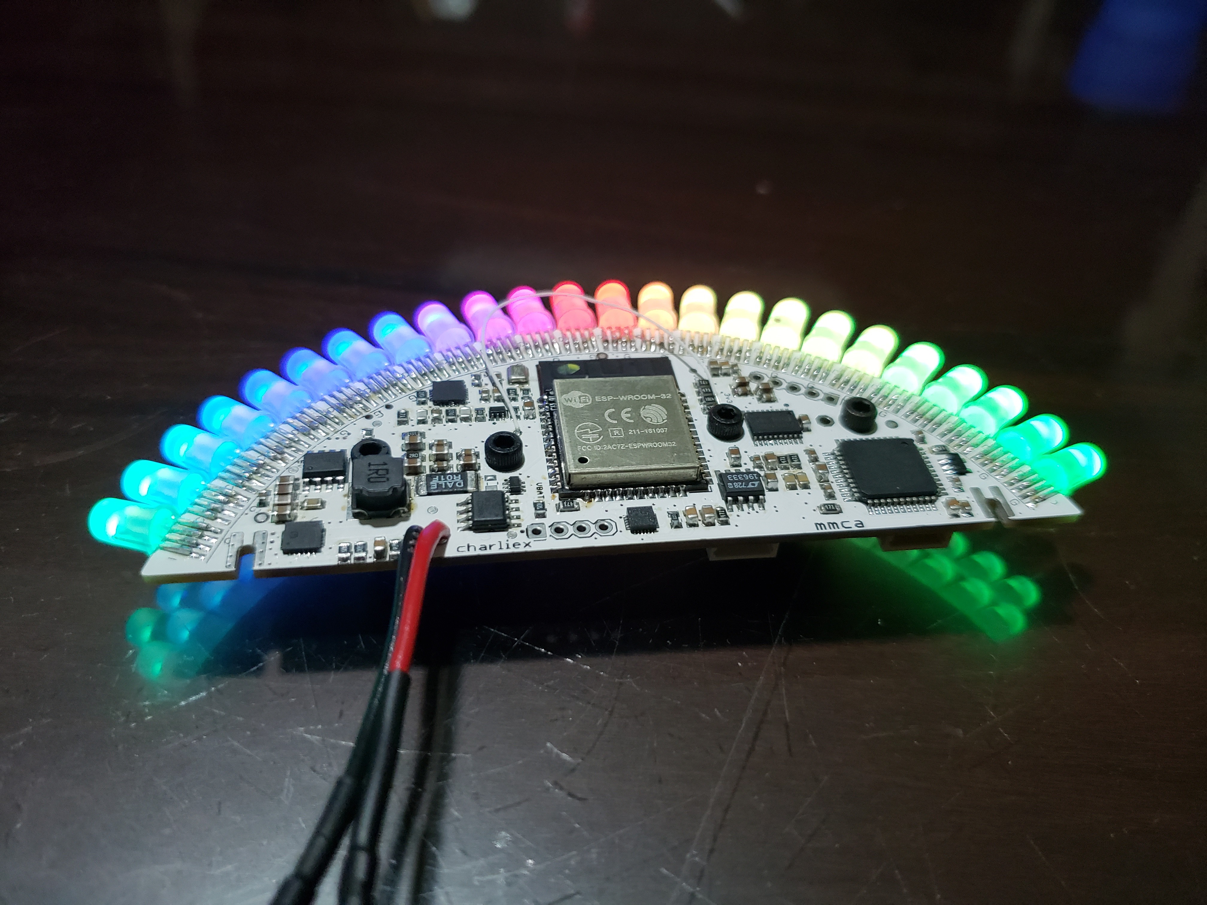
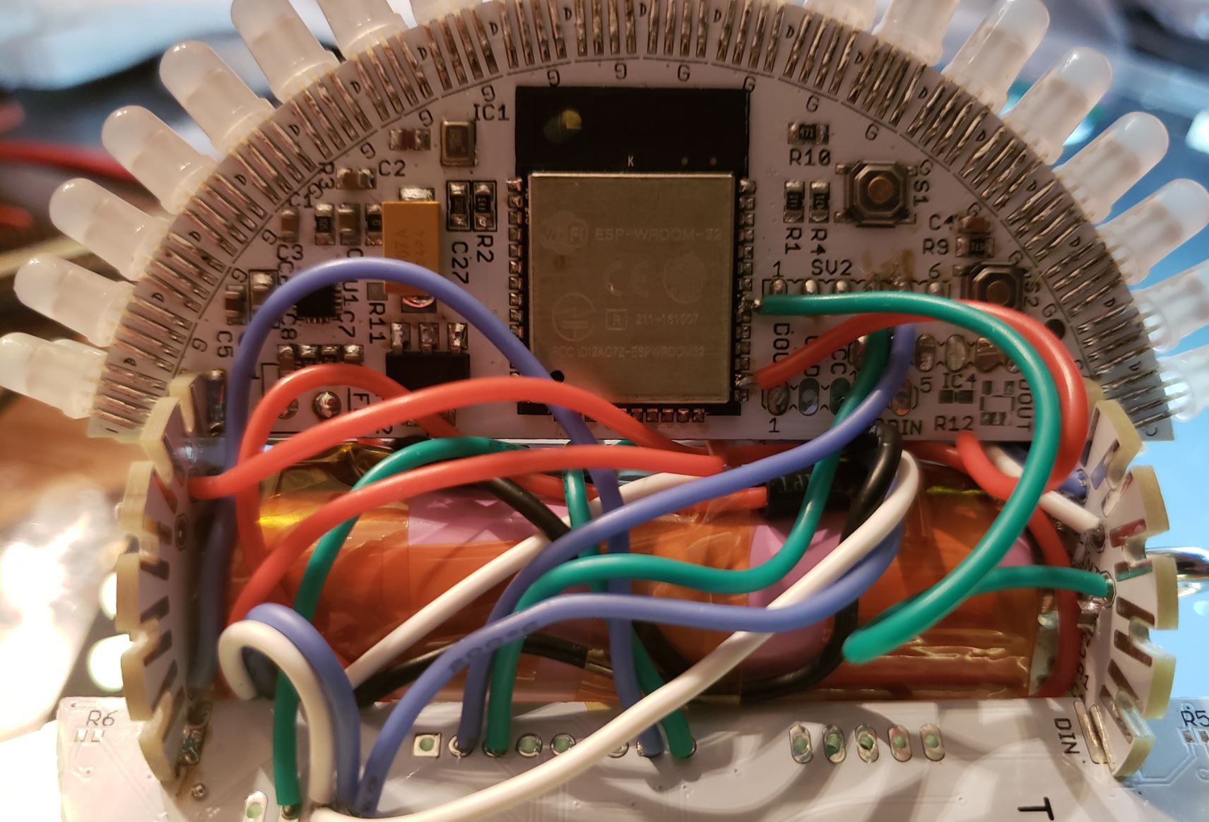
Behind that mess of wires is the ESP32 slice. We had the ESP8266 for some of the early protos but after using the EPS32 on the 2018 L1 badge, it made sense to switch. This slice also has an i2s microphone and DAC.
![]()
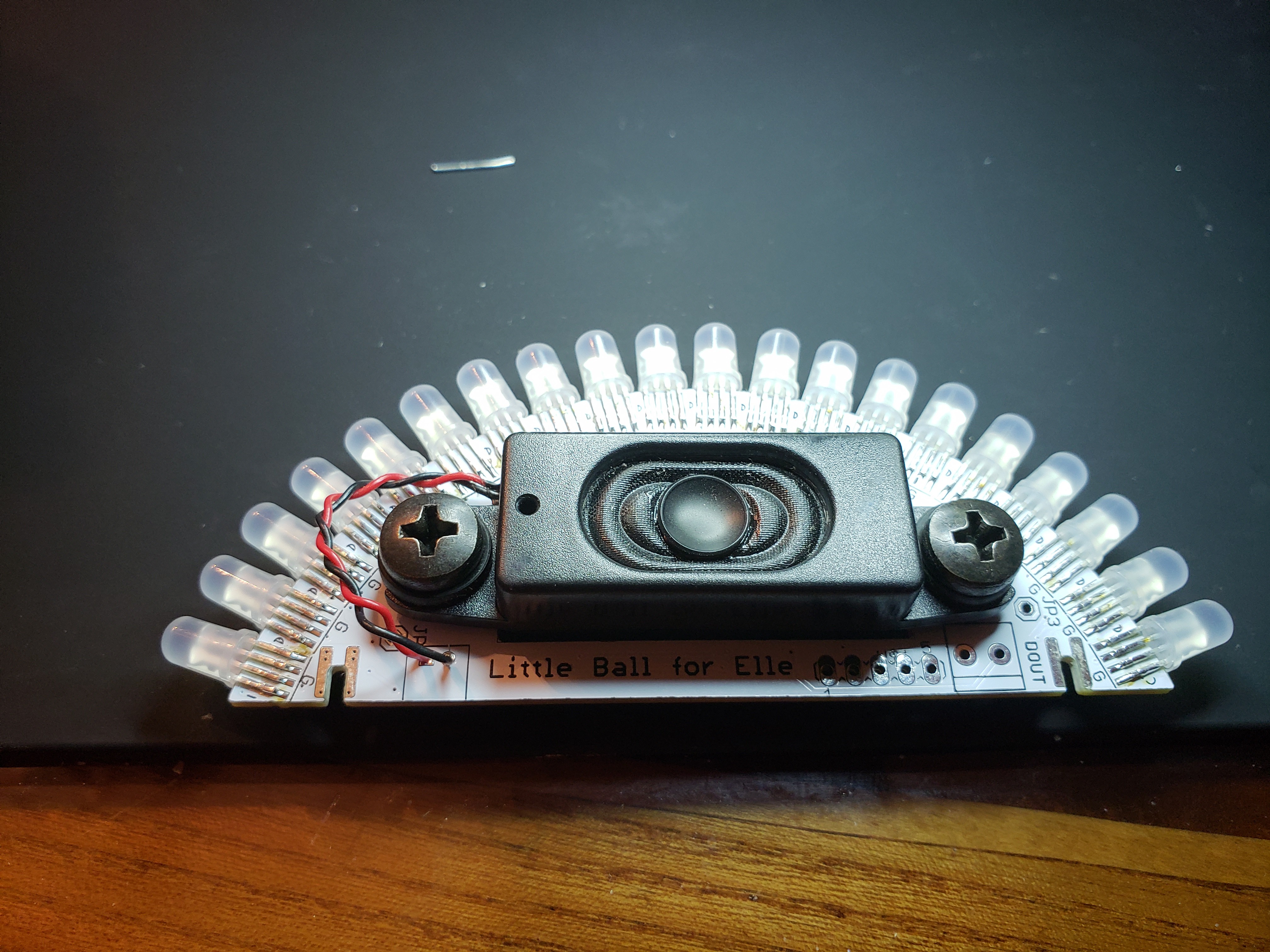
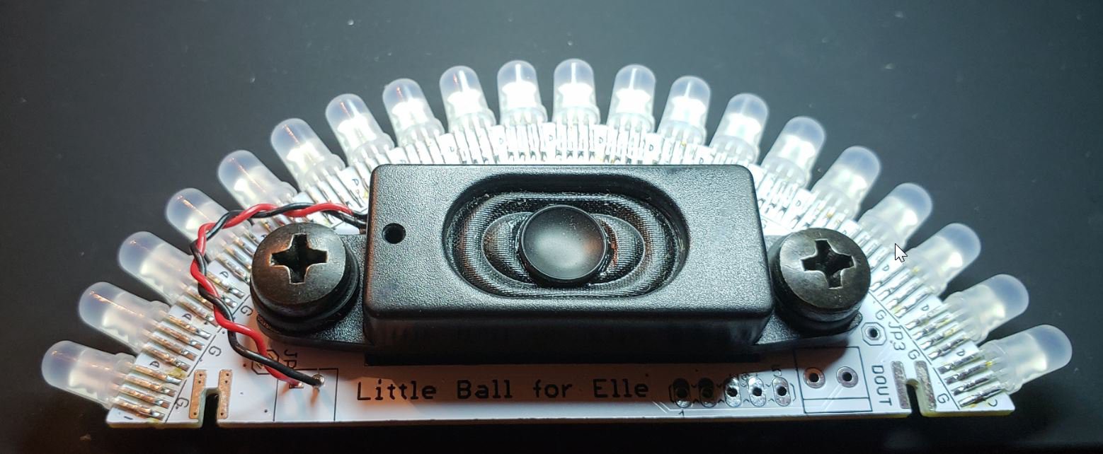
And here is the speaker slice. That is a little speaker from a Lenovo monitor, they are available oinline from a factory buy out.
What we wanted to do for the third revision was bring all the parts together back on to one slice. Bringing it back to the original vision.
![]()
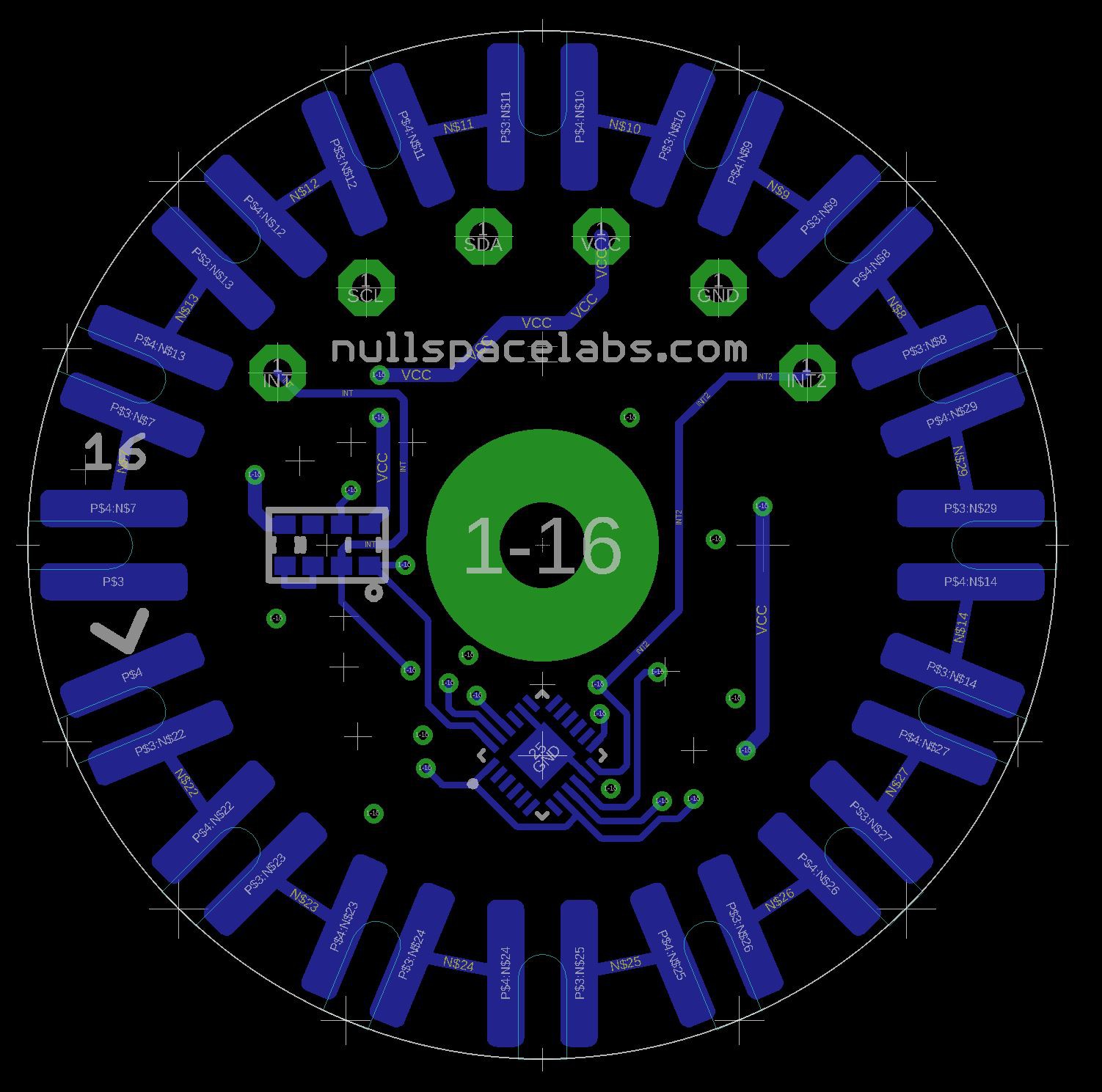
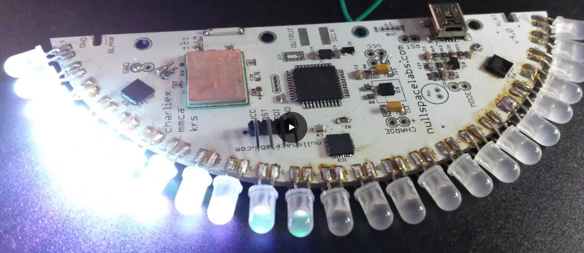
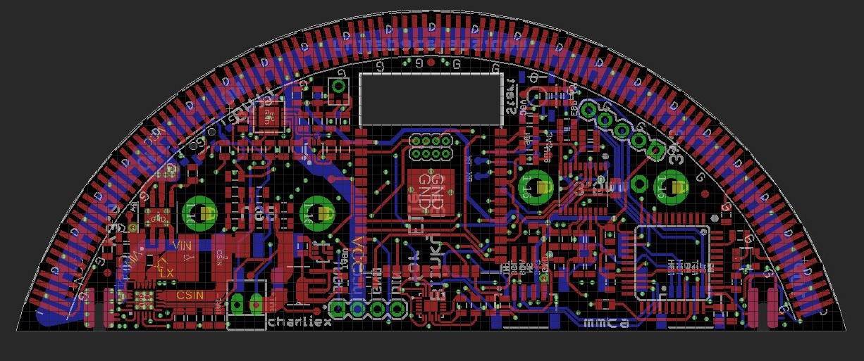
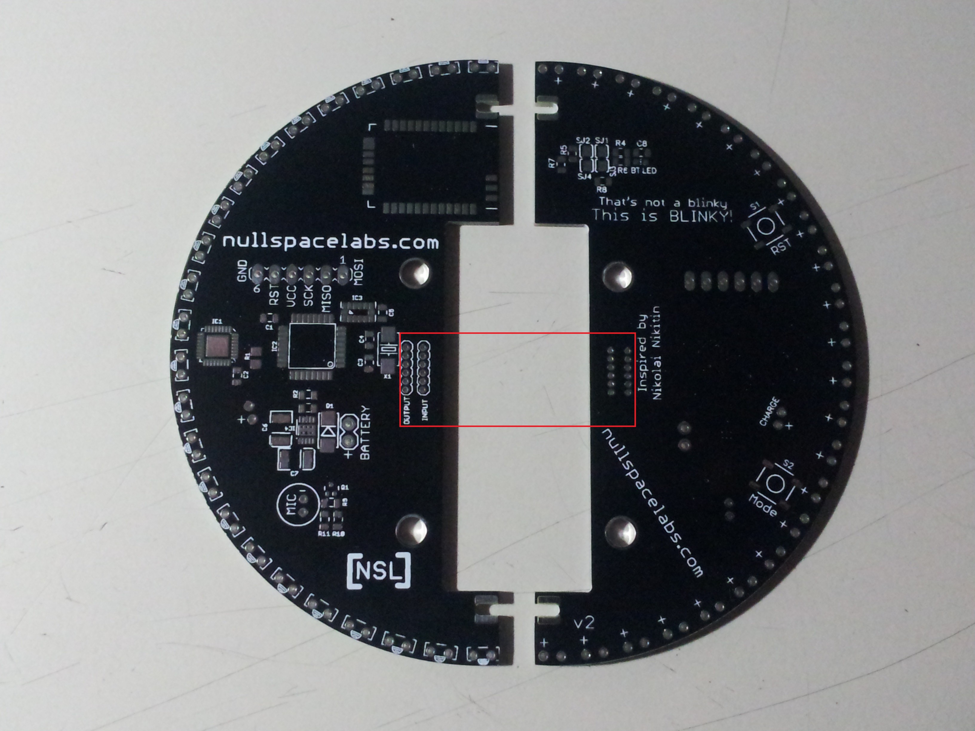
This is what the main slice looks like now... ESP32, LED driver, mic, DAC and all the power bits. It is off at manufacturing now, fingers crossed.
-
Connecting all the slices
06/27/2018 at 04:59 • 0 comments![]() In the first Blinky Ball we used wires to move the power and signal around the ball between slices. It was a little clunky and time consuming to build but seem to work OK.
In the first Blinky Ball we used wires to move the power and signal around the ball between slices. It was a little clunky and time consuming to build but seem to work OK. For the RGB ball we wanted something a little cleaner, more elegant. So we combined the structure and the signal path. The little slots that are soldered together to make the ball also carry the signals and power.
![]()
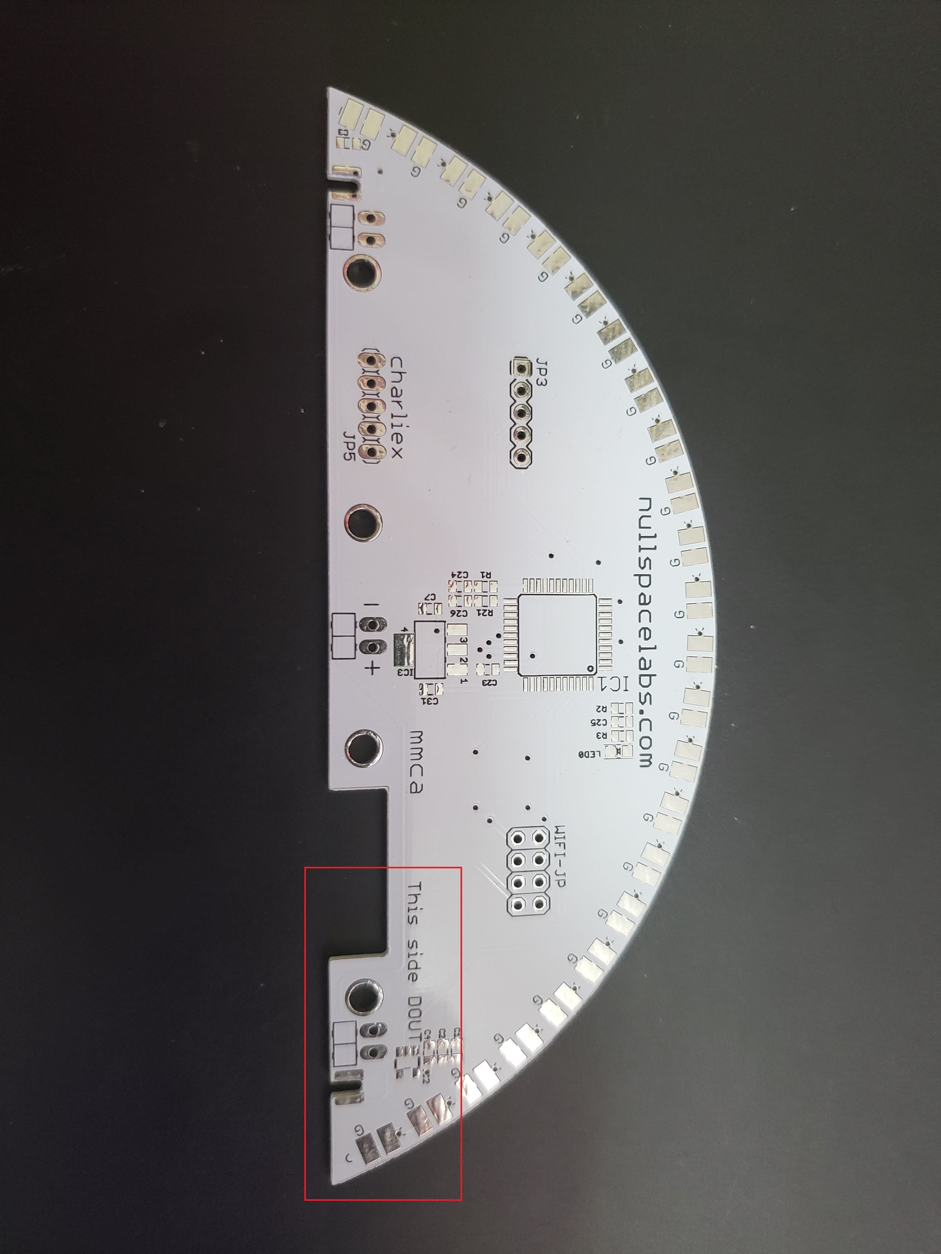
The top cap pass the signal from slice to slice connecting the DOUT from one slice to the DIN of the next. The bottom cap works in a similar manner but is just 5V and GND.
![]()
Unfortunately there are still a couple wires in the build. There are user buttons on the bottom cap and some sensors in the top cap that need to be wired. The battery is connected to the power slice by wires and that slice is in turn connected to the power distribution cap (bottom).
![]()
Still needs some cleaning up but its getting there.
-
Attaching LEDs to edge of PCBs
06/26/2018 at 21:55 • 0 commentsOn the earlier Blinky Ball with single color LEDs we just placed the holes near the edge and bent the LEDs over, it was easy and made for a very strong connection.
![]()
When we moved to an common cathode RGB LED with four legs it got a little trickier. It need to have four signals going to it, so I had this crazy notion of putting half the leads on one side of the PCB and the other two leads on the other side.
![]()
This worked pretty well, its very strong and the LEDs line up directly on the middle of the PCB edge. The main issue with this technique is that its a real pain to bend all the leads to fit on the PCB. Each LED had to have its leads formed, then clipped to length.
Next we moved to a WS2812 based addressable LED. It still has 4 leads, but they get daisy chained together. So in the current ball the PTH LEDs are just soldered in on their sides.
![]()
At first I thought this would be an issue as the LEDs aren't centered on the PCB edge, but you really cant tell. I also had concerns of the LEDs ripping off the pads, but it seems having 4 long pads is plenty strong. (Yes, that's a speaker... more on that later.)
-
Recycling some LayerOne badges
06/26/2018 at 06:57 • 0 commentsOur first blinky ball was monochromatic and run by an AVR driving some TLC5947s. It worked very well but was a little expensive as each slice needed its own TLC IC.
If we had done the same setup for the RGB ball it would have been 3 times the cost in driver ICs as each 5mm LED has three light emitting junctions.
For the LayerOne 2015 conference badge (and again in 2016) we had a PSOC4 driving WS2812 LEDs. (Fun fact, the circuit comes from charliex's Christmas lights in 2014... when we like a circuit we really milk it.) This was great as you can make a 'serial block' on the PSOC4 that drives the LEDs and you get an ARM core all in one package.
Now if only you could mount the 5050 WS2812 LEDs on the edge of the PCB or if they made WS2812 LEDs in PTH that I could mount on the edge of the PCB.
Well it turns out they do make WS2812 LEDs in a 5mm PTH. I got a couple of those and soldered it on to a LayerOne badge, and Yay! it worked perfectly. First little part of the puzzle solved.
Next we need some power, the WS2812 LEDs need 5 volts the PSOC4 needs 3.3v and I want to use a 18650 Lithum Ion that runs a nominal 3.7v. So what I would normally do is go through the TI catalog looking for a boost IC and a charger chip. In fact that is what I did for the 2017 LayerOne badge. It was a great power circuit, it let you charge the battery from USB and boosted the voltage to a nice steady 5V. Unfortunately it cost about 10 bucks for just that little power section. Charliex pointed out that what we needed was a battery bank and from there we tracked down some highly integrated power bank ICs that do boost/charge all in one chip. So the Blinky Ball uses the same power section as the 2018 L1 Badge (same idea as the 2017 power section, with a less finicky power SoC).
And speaking of the 2018 L1 badge, the blinky ball has the same ESP-WROOM-32 for bluetooth and wifi connectivity and a mic and speaker.... for reasons.
 In the first Blinky Ball we used wires to move the power and signal around the ball between slices. It was a little clunky and time consuming to build but seem to work OK.