 Matthew James Bellafaire
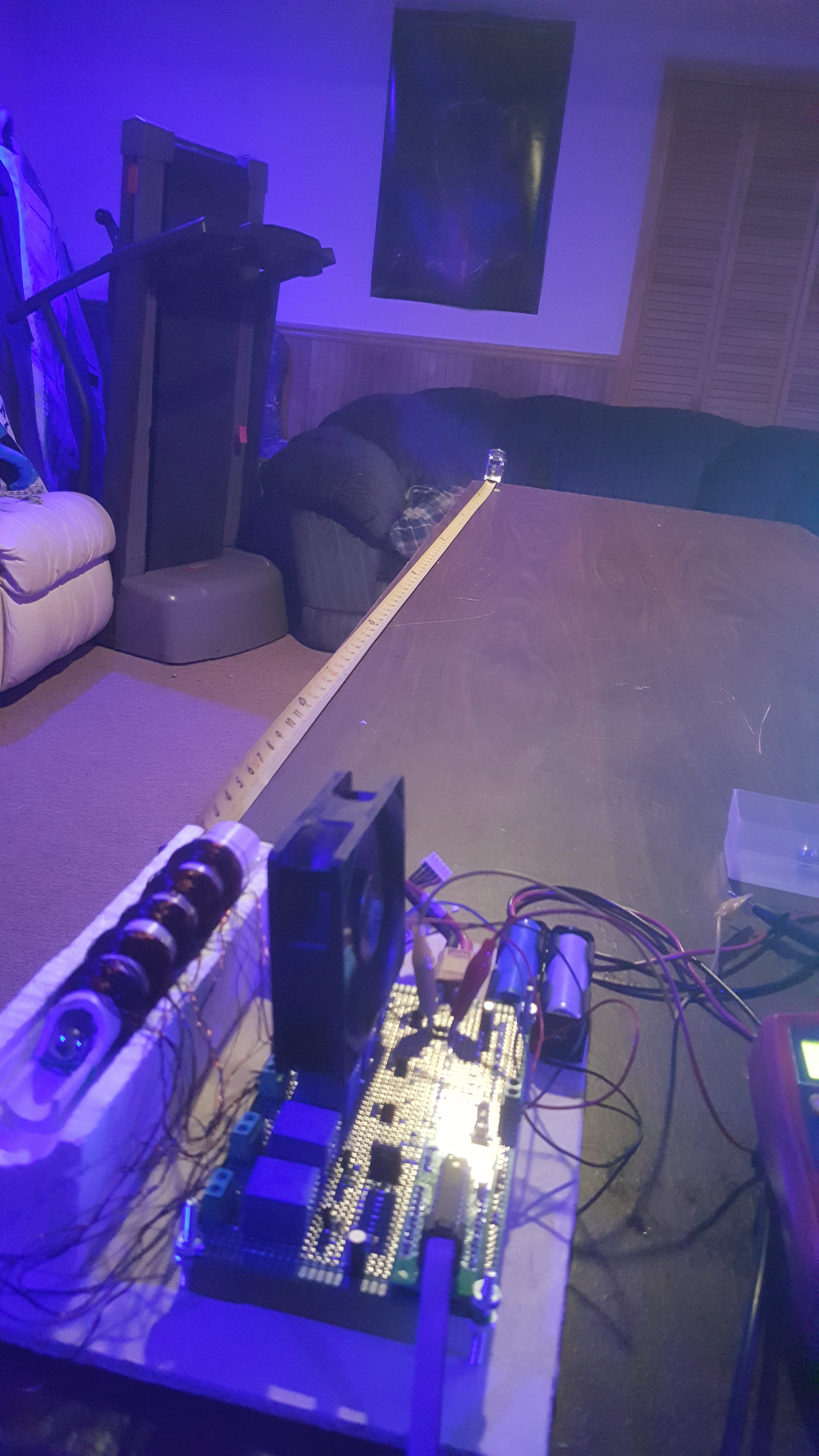
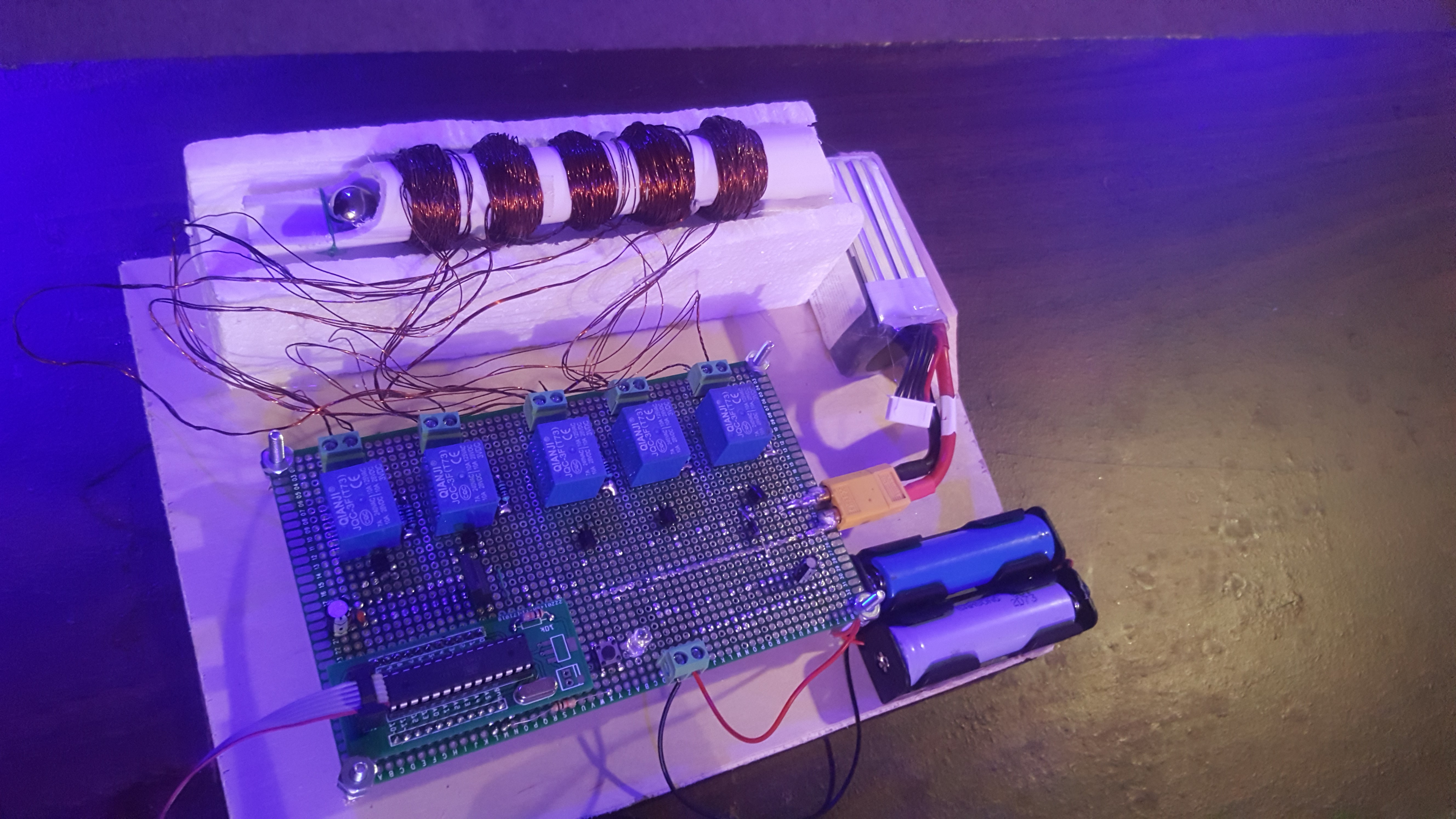
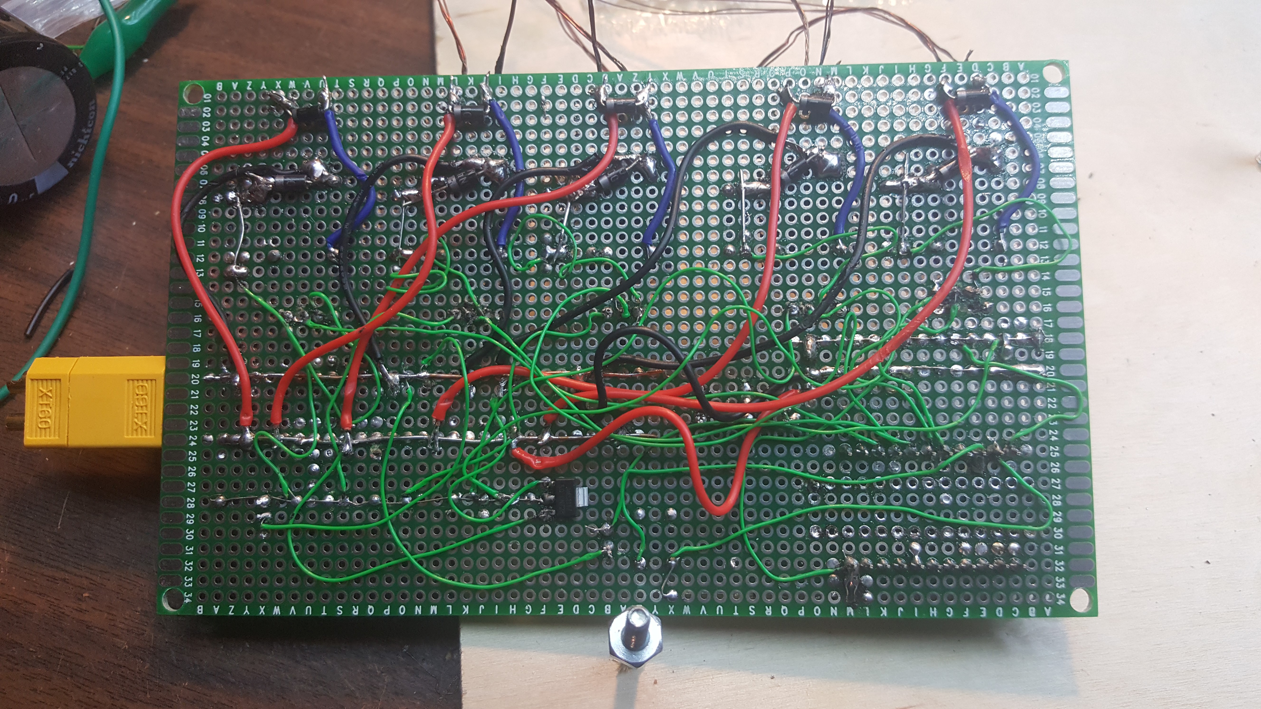
just a 5 stage coil gun using relays and an atmega328. here are some videos of the final project
0%
0%
5 stage coilgun
5 stage coilgun to fire 1/4" ball bearings
Become a Hackaday.io member
Already have an account? Log in.
Just one more thing
To make the experience fit your profile, pick a username and tell us what interests you.
Pick an awesome username
hackaday.io/
Your profile's URL: hackaday.io/username. Max 25 alphanumeric characters.
Pick a few interests
Projects that share your interests
People that share your interests

 Kal
Kal
 Jesse Farrell
 Sanjit Sarda
Magnetic force is proportional to the field GRADIENT, so you could about double the force by collapsing each coil's current after the ball passes. Due to the coupling between adjacent coils, this discharge and charging the next coils current will be faster in this case. Also, the field at the end will not rob you of your velocity by attracting the ball back toward the gun after it passes the last coil. Second, the ball is accelerating, so you could relax your timing issues by spacing the coils quadratically along the barrel... x(t) = 1/2 a t^2. Finally, a good conductor (i.e. copper) could be pushed ahead of the coils much stronger than a ferromagnetic ball can be pulled into the coils due to eddy currents in the steel. If you utilize this advice, you will need MUCH more mass in the gun to absorb the recoil; this mass will need to support the coils very thoroughly and will need to be an insulator. A ferromagnetic insulator would be better still. CAUTION: Eddy currents will heat the copper in this case.