-
Possibly the Final Update
09/15/2018 at 13:23 • 0 commentsThe mini Solar charger has gone well and I think I'm ready to move on to my next project.
The past week I've been tackling problems with the battery draining too quickly when the device is not in use. Changing the code to run in sleep mode seems to have fixed this pretty well, and now I expect the battery to last a bit over a month in total darkness. The main cause of discharge now is backflow through the solar panel, which I measure at 0.6 mA. Adding a diode would fix this, but lob off a good chunk of efficiency (a good Shottkey diode would cut about 10% off).
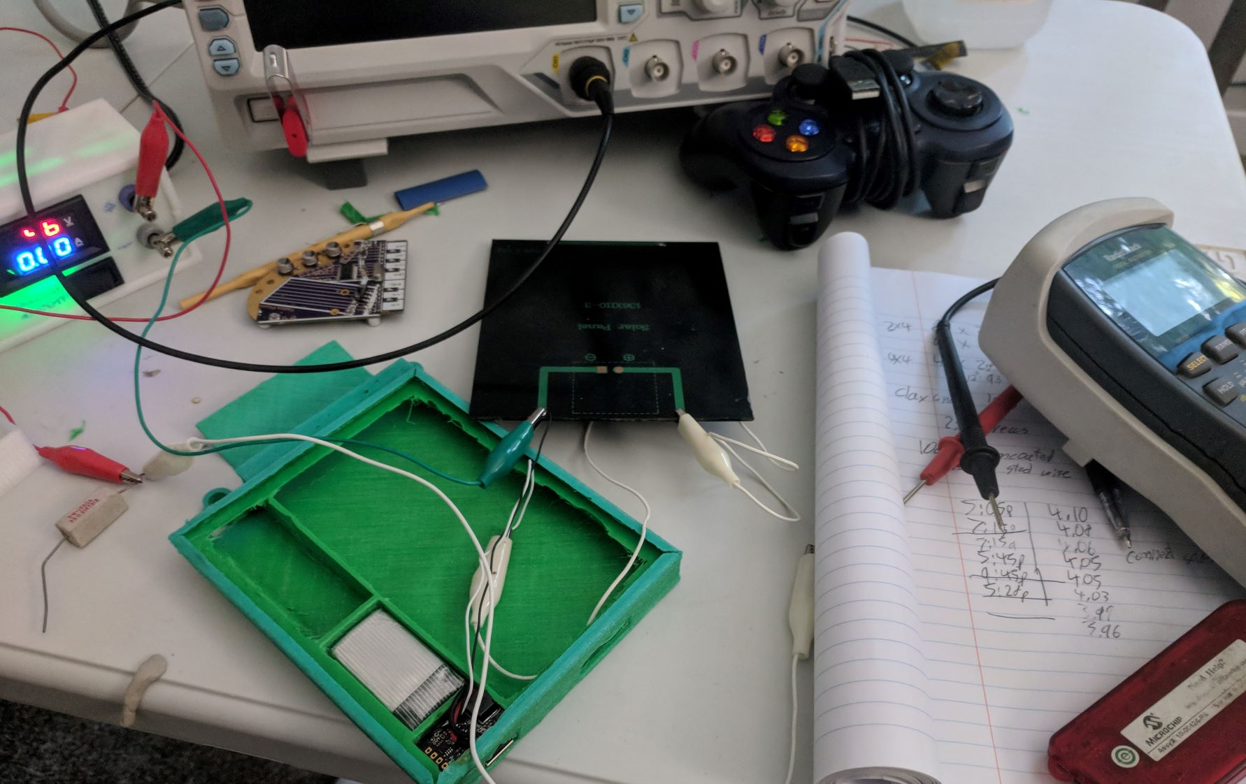
Messy discharge measuring setup. The circuit is working just as I expect it to, but the solar panel is underwhelming. I knew going in that 2 watts is pretty minimal, and you usually get much less than that.
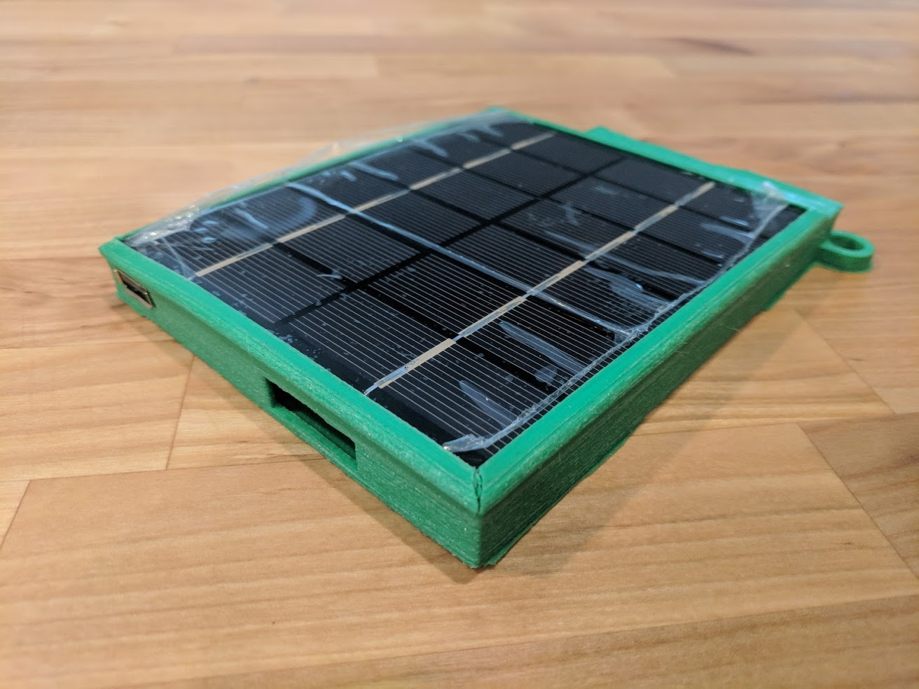
I also might put more thought into the enclosure. It fits pretty well; overall I'm happy with it. It's not totally sealed but could probably take a splash. The phone slides in and out okay, and the top flap keeps it tucked in. You can see in the picture that the sun has discolored the filament, but I haven't noticed any other property changes.
I do have a bit of a heating issue. When charging an iphone with it inside the pocket, the phone overheated to the point where it refused to charge. The solar panel gets pretty warm in the sun, and with this design, that heat transfers right through.
I might ditch the pocket idea altogether; the user probably already has a more secure place for their phone.
That's all for now. I'm going to go back and update my documentation, get a few action shots, performance specs, etc.
-
Efficiency Testing
08/31/2018 at 14:11 • 0 commentsIf you don't feel like reading this: 90% efficiency, with some unfortunately large error bars.
I finished putting together the Rev 2 prototype, tweaked the firmware a little, and it works! Both the input and output converters are doing their job, power points are tracked, the LED does exactly what I want it to.
I wanted to put together the whole thing and mark the project as complete, but there's one more thing I need to test:
Was all of this worth it?
I added a buck converter with MPPT to this circuit on the belief that I would get more energy from that than simply connecting the solar panel to the battery. And while I picked out efficient parts, I didn't have a good way of estimating the efficiency of the build before putting it together.
Therefore, today's lesson: How to measure efficiency.
Recipe for Power Efficiency Measurement
Ingredients:
- A 4-channel oscilloscope
- 2 Precision low-value resistors
- An appropriate power supply
- An appropriate load
- A converter to test
Step 1: Preparing the ingrediants
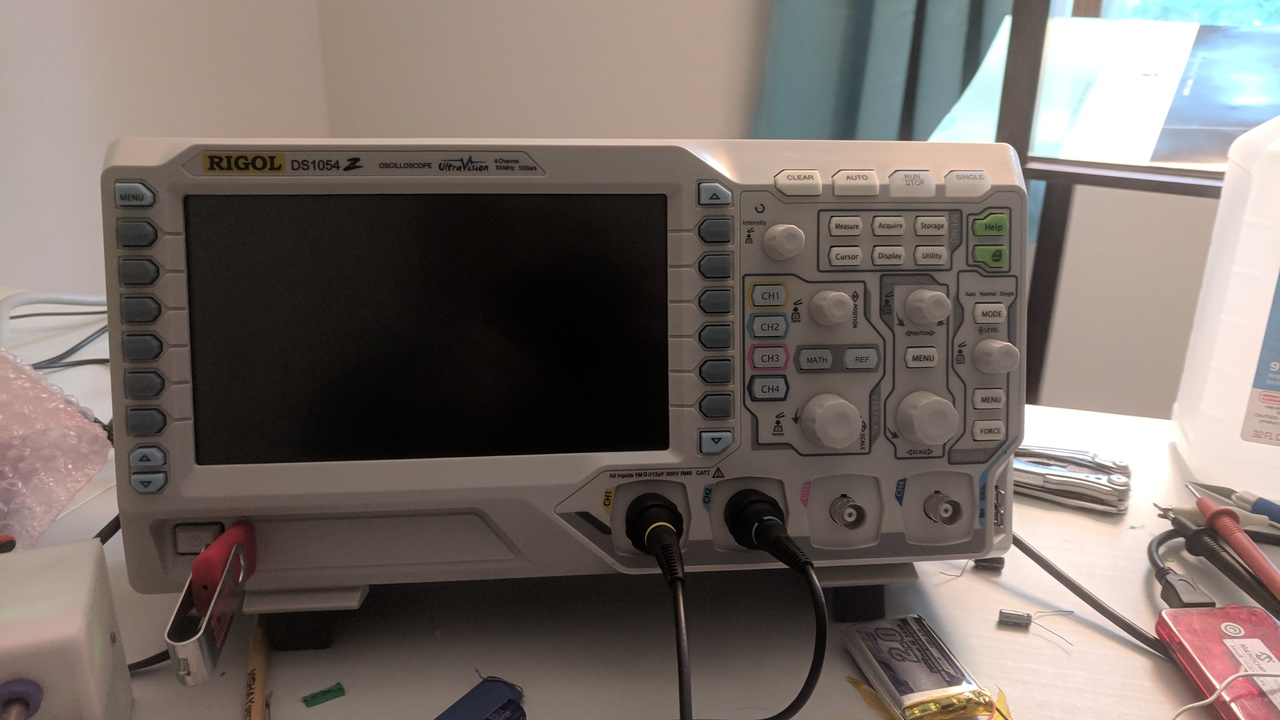
- A 4-channel oscilloscope
Rigol. No surprises there. First time I've gotten to use all four channels though.
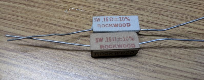
- 2 Precision low-value resistors
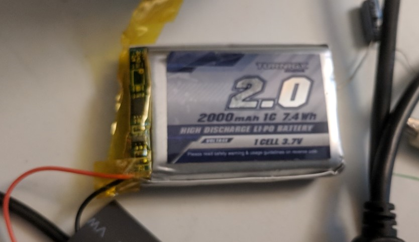
I dug around my parts bin and found these bad boys:
Oops, did you say precision? I thought you said +/- 10%.
We can fix this. Power supply + DMM + Scope = Precision resistance measurement.
Input current resistor: 5.06 Amps of current generates 0.988 V -> 0.195 Ohm. Well outside even the loose tolerance specified. I double-check all my connections; either my instruments are way off or this resistor is. I'd like to trust my instruments, while these resistors are many decades old. I'll take the measurement as fact.
Output current resistor: 5.06 Amps generates 0.946 V -> 0.187 Ohm.
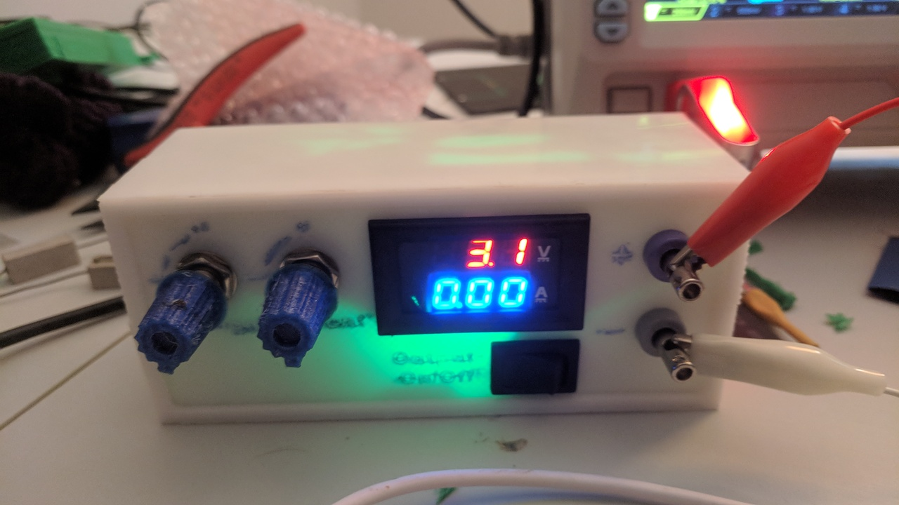
- An appropriate power supply
Home made! And crappy! But it does the job, even if I can't really control the current and the current measurement is off by nearly a factor of 2. I built it based on this: https://www.thingiverse.com/thing:2085223
Since my converter expects a solar panel as an input, I add a 33 ohm series resistor out of the power supply. That way, it has a well-defined maximum power point at 1/2 the source voltage.
- An appropriate load
My converter expects to charge a battery, so this little lithium cell is my load. It's different from what I intend to use in the final device, but it has some on-board protection, which will be good when I accidentally short this thing out.
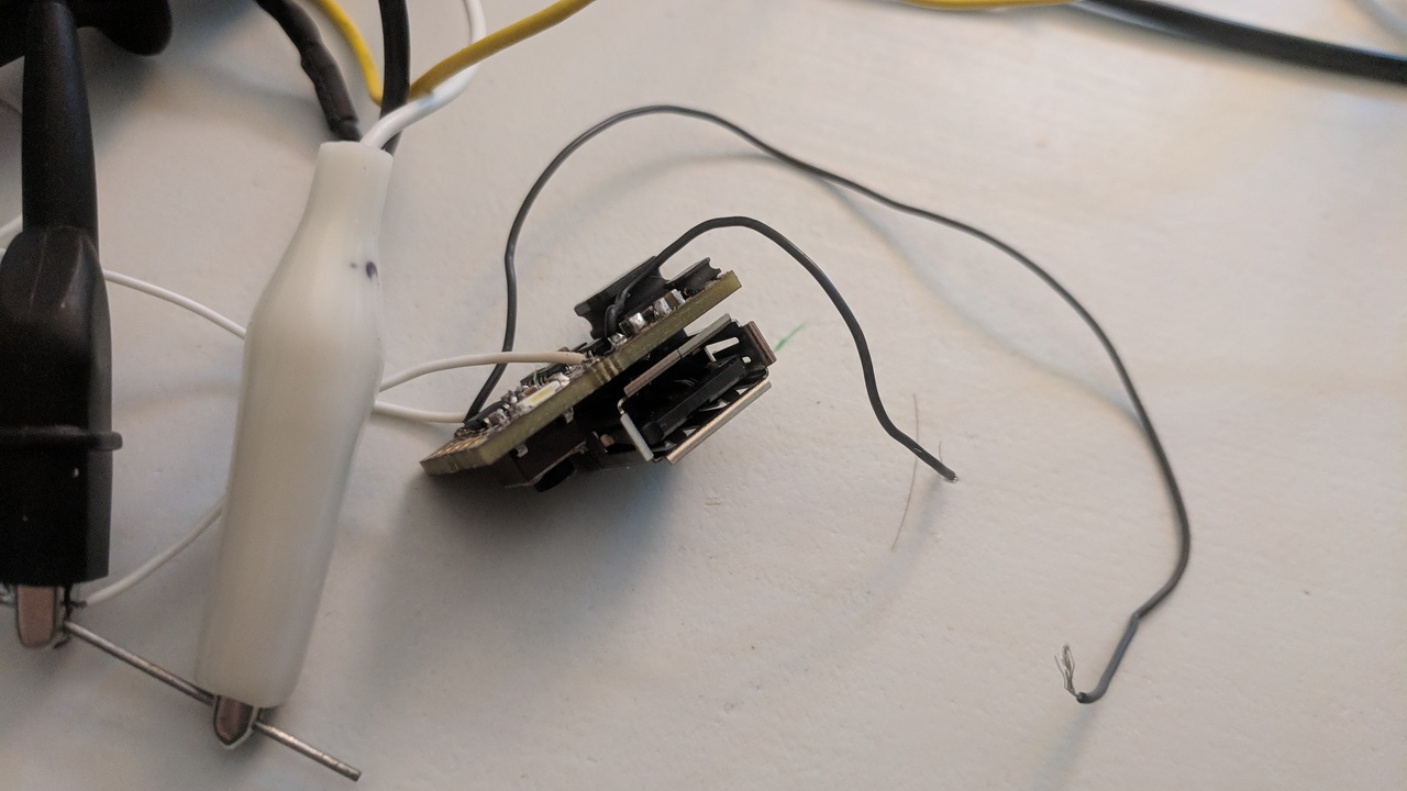
- A converter to test
Right here on my desk. Did I mention it's small?
Step 2: Setup
In order to measure efficiency, we need to measure the input power and output power, as your standard efficiency formula shows:
To get electrical power, we need voltage and current, according to P = V * I. So our formula is:
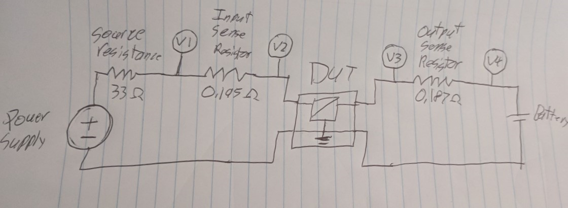
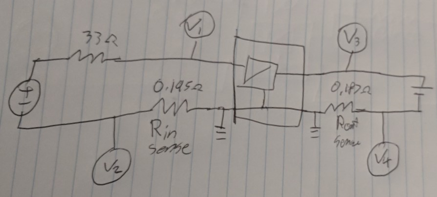
Problem with this is that I can't measure current with my oscilloscope. I can with the DMM, but I only have one of those. This is where the "precision" resistors come in. By measuring voltage on each side of a known-value resistor, I can calculate the current running through it. Therefore, I want to set up my circuit like this:
Note from the future: This won't work; don't do this. I'll find that out later.
By substituting my voltages and currents with the values I measure and calculate, I arrive at the following:
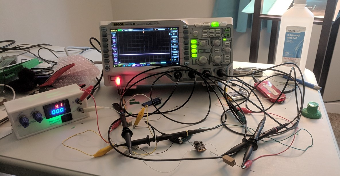
It's not the prettiest thing wired up:
Step 3: Run (away)
For this test I'm going to use my standard code. Battery level is 3.8 Volts, switching frequency 40 kHz. I'll shoot for about 100 mA input current. We'll fire up the power supply, wait for things to level out, and take a capture of the data. The math functions on this scope aren't sufficient to carry out the formula above, so I'll import the raw data to MATLAB.
I take the data onto a USB drive, load it up in MATLAB, and do a little this:
>> mean((CH3 .* (CH3-CH4)/0.187)./(CH2 .* (CH1-CH2)/0.195))

ans =

    0.1336
...What? I know for a fact this is more than 13% efficient.
I tried again, this time ground every individual scope probe, and tweaking my function to average each value before inserting them into the equation...
>> (mean(CH3) * (mean(CH3)-mean(CH4))/.187/(mean(CH2) * (mean(CH1)-mean(CH2))/.195))

ans =

    1.1277
Well, that's... better?
Step 4: Hang head in shame
I was so antsy to do this test, I forgot something: Oscilloscopes aren't super precise with DC values. So my method of measuring current is flawed; I can't get a reasonably precise reading by subtracting two probes. Let's try again:
Another note from the future: this only works if your power supply has an isolated output. Oops.
This time, I measure each current with a single probe, and I can turn up the gain to measure much more accurately.
So I tried that, and discovered that my power supply isn't isolated, which means current could bypass the input sense resistor through ground. So this scheme isn't any good either.
So I'm going to have to do this the old fashion way: Probe voltage 1, probe voltage 2, break circuit and probe current 1, same with current 2. Write them all down, pull out the calculator.
Here it goes...
Vin: 4.62 V
Vout: 3.92 V
Iin: 165 mA
Iout: 170 mA
That gives me 3.92*170 / (4.62*165) = 0.87
If that's right, my circuit's efficiency is about 87%. I'm sure there's a great deal of error bars in there, and maybe I'll have to come back to this experiment. My main concern is that my circuit isn't operating exactly the same during all 4 measurements. But for now, I have a number, and it's in the range I expected.
But that brings back the question: is it worth it? This experiment shows my output current only slightly higher than the input current, so it's a very slight gain. However, the input voltage is pretty low; my solar cell's MPPT voltage should be closer to 6 volts. What if I increase my supply's voltage?
Vin: 5.20
Vout: 3.95
Iin: 166
Iout: 200
3.95*200/(5.2*166) = 92%
Not bad, and a pretty big boost. A linear converter in this instance would only get me 3.95/5.2 V = 76% efficiency.
One could extrapolate from this. Imagine my solar panel at its average of 6 V, and battery cell at its average of 3.6 V. A linear converter would get me 60%, where mine seems to average around 90%. That's 50% more power I'm getting out of the solar panel!
Step 5: Act all confident
So yeah, I think that answers my question. My tiny boost converter is getting me a good deal more power out of my solar panel, optimistically 50% more power. And if anyone asks, I totally measured that exactly on my first try and didn't have any issues at all!
At least, now when I see 4 high-precision DMMs stacked up, I'll understand they needed that many.
-
Rev 2
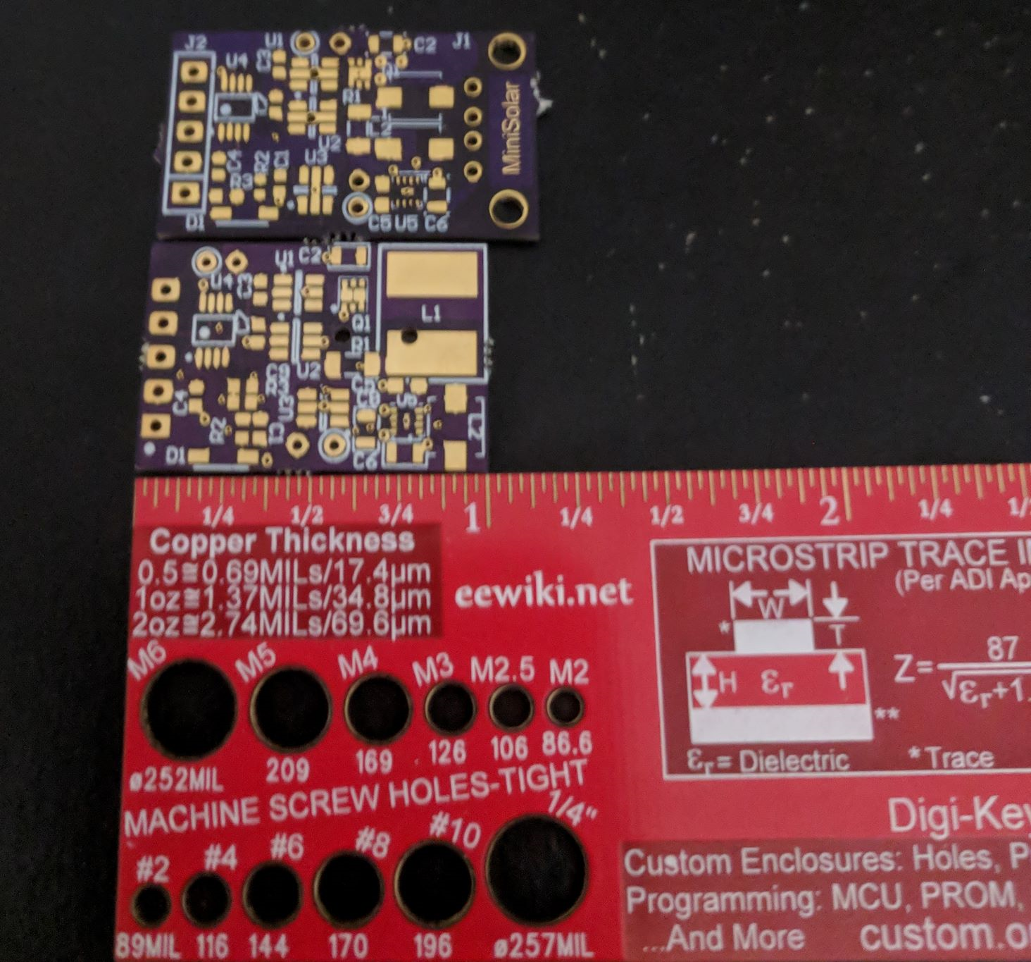
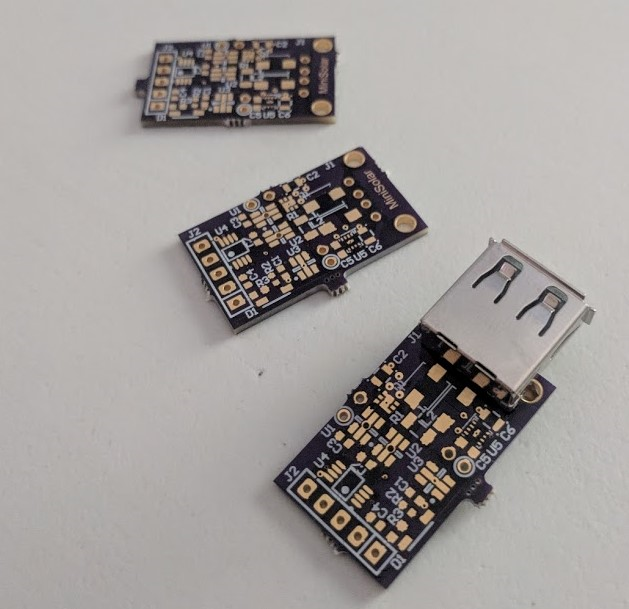
08/28/2018 at 02:26 • 0 commentsSecond revision boards arrived today. Probably the nicest part of this project is how cheap I can get 5-day-lead PCBs from OSH Park.
Here's how Rev 2 (middle) measures up compared to Rev 1 (above) and my PCB ruler (below):
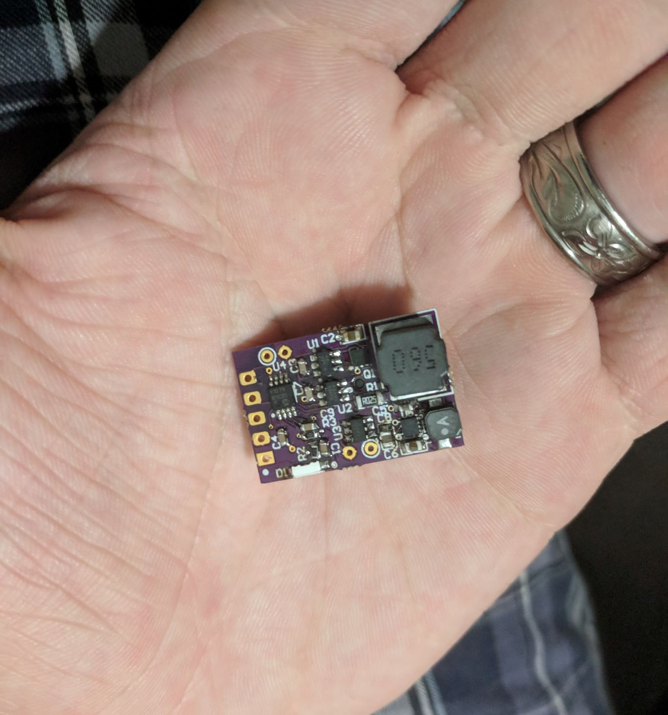
And, for perspective, the assembled PCB in my hand:
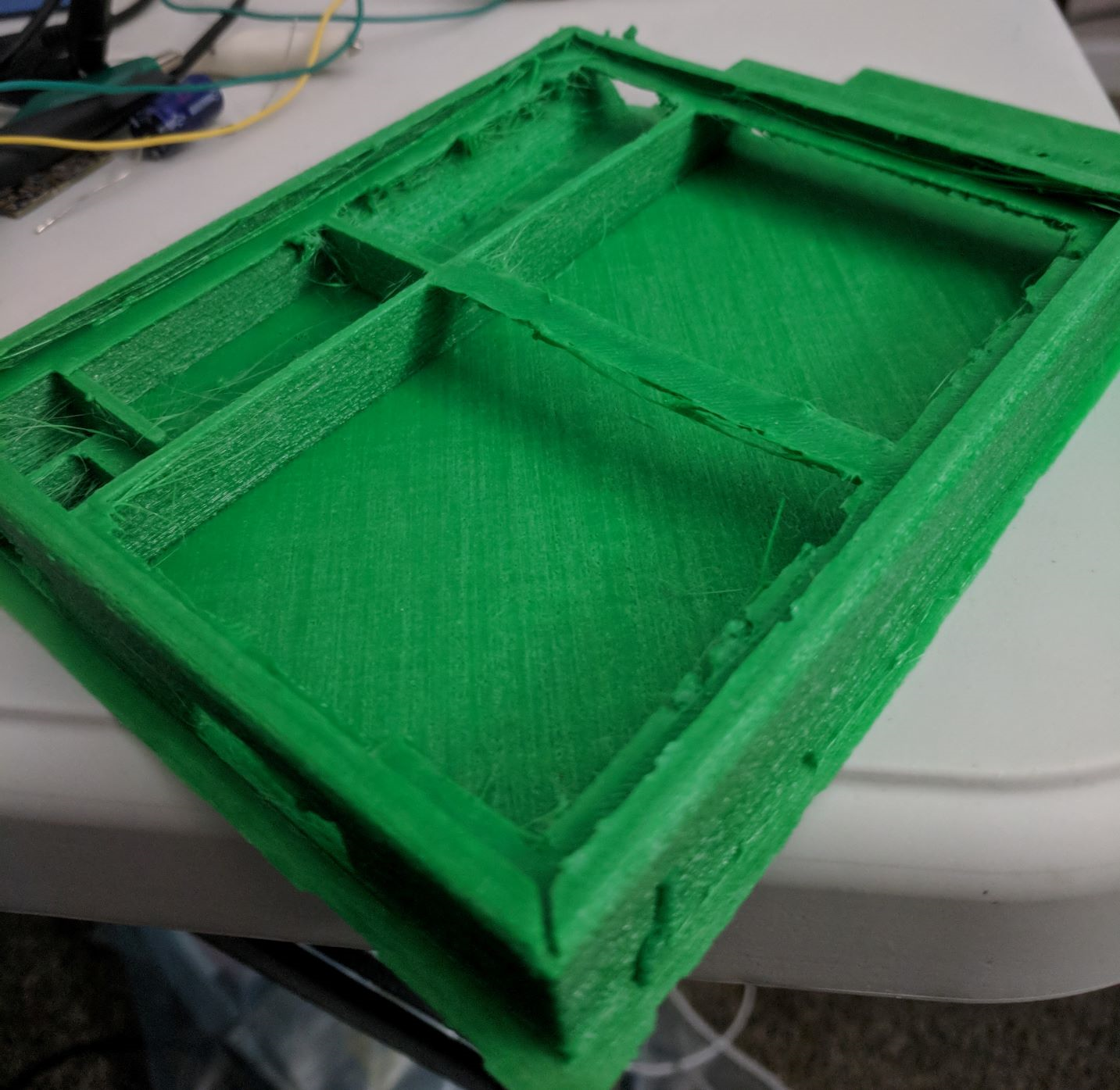
Lastly, I've been working on the enclosure some more. I've been having a bit of trouble printing with the flexible filament. I learned that hard way if your print head is calibrated too close to the bed, normal filament will over-extrude, but flexible filament will simply jam up. I have that sorted out, but now I'm finding that flexible filament is nearly unworkable with support and bridging. Below is Rev 2 of the enclosure, before cleaning.
I might have to get creative. If only I had a multi-material printer, eh?
Oh well. I'll find a way to clean up the enclosure, get the Rev 2 board working, and then I should be pretty much done!
-
Version 2
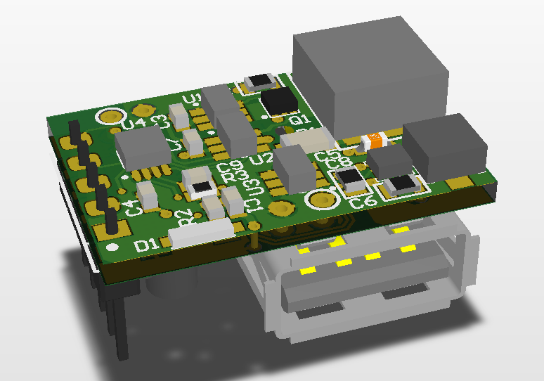
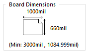
08/18/2018 at 23:37 • 0 commentsI'm ready to send out the second revision. It looks like this:
That's .66 square inches of handsomely packed parts.
Besides the mechanical reconfiguration, I put on a bigger inductor, and pushbutton, fixed some of my footprints, added a little capacitance, improved the microcontroller pinout, and added some filtering on the current sensor.
-
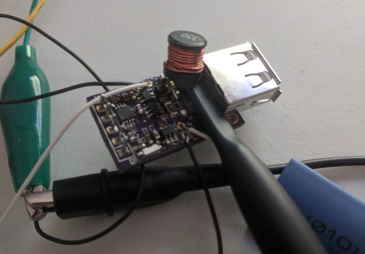
Update: Circuit Working
08/13/2018 at 23:18 • 0 commentsGot it up and running! After a good day's work fixing my soldering, writing some test software, debugging, scoping, etc. I have a working circuit board and very basic firmware.
And...it looks like this now:
So... the inductor. Obviously this isn't what I had in mind. I guess I was too excited to get a board ordered to actually calculate the inductance I needed in the buck converter. My original was a 1 uH inductor. This is what was called out for the boost module, so I figured the buck had similar needs and could use the same inductor.
Which is obviously wrong. The boost module has a switching frequency in the megahertz, where the highest I can get the microcontroller to do is 320 kHz (160 kHz if I need 100 steps of PWM).
So I scrounged and found the big through-hole inductor shown, and got that to work.
In other news, turns out I misinterpreted the rules for the one-square-inch challenge (or they changed the rules all the sudden?). They want the entire board to fit, including the components. This doesn't fare well for my big USB-A connector hanging off the edge of the board.
The USB connector needs to be there; it'd be stupid to not have it, given the board's intent is to be a USB charger. I could move it off the board, but that's not a clean solution. I have enough flying leads already.
So how to fit the connector within my square inch? My first thought was a vertical connector, but that makes the positioning awkward. So I think the solution is to switch to a surface-mount connector and put it on the back of the board. This makes the board thicker, but I think it'll work if I keep all the big parts on the bottom.
I'm a little upset that I have to redo much of the layout to make this work, but I guess they call it a "challenge" for a reason. And I have to redo a good chunk of it to fix my footprints and get a bigger inductor on there. Maybe I'll even have space for some more input capacitance.
Anyway, I should have enough time for a respin. Next step is finishing up the firmware, doing some testing, then I can respin and get a nice final product.
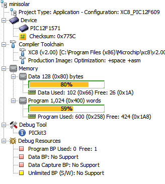
And speaking of firmware:
80% data memory usage already? (tugs collar nervously) I can safely say I've never pushed a microcontroller this close to its limits.
-
Woops...
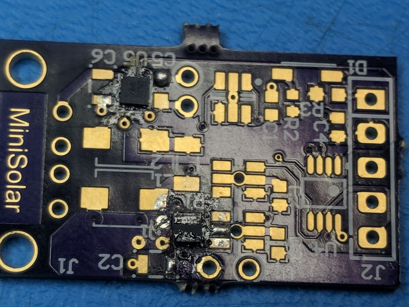
08/11/2018 at 17:25 • 0 commentsI quickly found the first issue with my PCB. I have to admit, this was a pretty stupid mistake.
Note the numbering order. It's clockwise, but should be counter-clockwise. This means pins 1 and 3 are swapped, as are pins 4 and 6. What I was thinking when I thought the numbering should be clockwise is beyond me. I assume I was looking at a drawing of the underside of the part when I was doing the pin order.
At first I thought that was it. There's no way I could fix a layout that tiny, I'd have to reorder the board. But, with some really careful cut and rewire, I managed to do the pin swapping and verify that all the new connections were good. Felt like a freaking superhero when I finished, too.
See part is in the bottom-center. It's certainly not ideal, but besides the excess flux the repair is barely visible and should hold up. Hopefully the tiny wires I had to use won't add too much resistance.
Hopefully the rest of the assembly goes more smoothly.
-
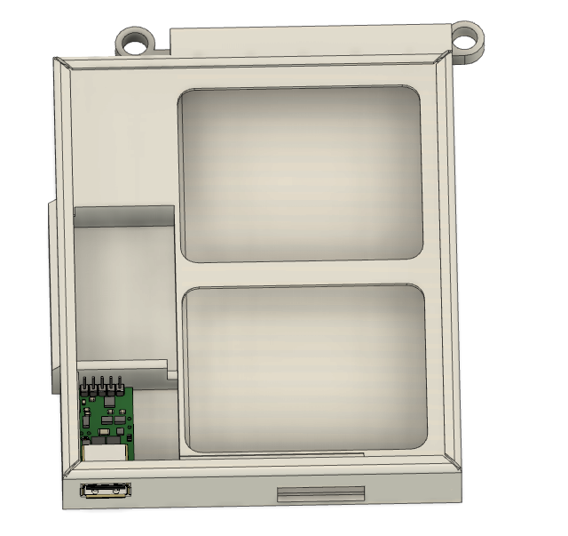
Mechanical Design
08/10/2018 at 22:51 • 0 commentsWhile I wait for my boards to be delivered, I spent some time working on the mechanicals. I've been 3-D printing for a couple years now, but this project made me want to try something new: Flexible Filament. I ordered some green TPU from a brand called Priline.
I designed this as sort of a phone pocket, with extra width so that the front would fit the solar panel. Some space is cut out of the sides for the battery and charger circuit.
I designed this in Fusion 360. Here's a link to the design: https://a360.co/2MyXXA5
Here it is after a couple revisions:
One problem that I came to a neat solution on: sealing in the battery and charger. Eventually I got the idea of using the solar panel itself to close up the "box" that the other parts go in. This saves material (weight) and makes everything a lot simpler.
I printed out an early revision to test the fitting. Most of it is encouraging, but I found a lot of things to change. Printing with flexy filament went pretty well once I dialed in the heat settings (reducing the print bed temperature did wonders). But, as expected, the stuff doesn't bridge well, so a part like this takes a quality hit.
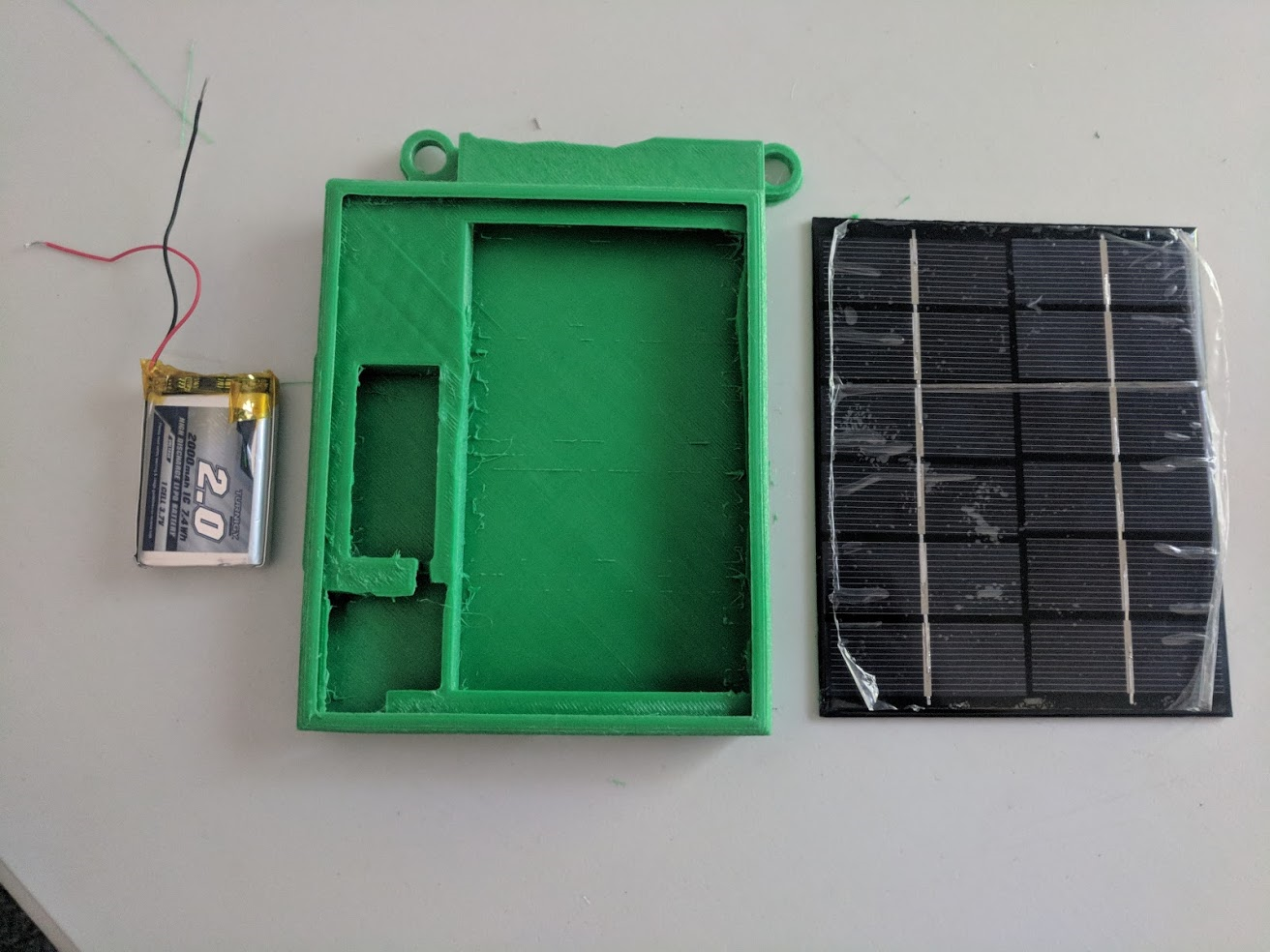
Here are my parts layed out...
And assembled...
My PCBs just arrived from OSH Park. They look like they might be a little tricky to solder, but I'm up for a challenge. These are the first revision boards that have a length just a hair over one inch, though I already designed a revision that fits in a one inch square. Next up: build and test this thing.
-
Project Design
08/07/2018 at 19:10 • 0 commentsTheory of operation:
The miniSolar is designed to take in power from a 2-3 watt solar panel, charge a small lithium battery, and charge a device. Since USB devices tend to draw a constant current, the battery buffer is required to supplement the solar power when it's insufficient to charge the device by itself. This has the additional benefit of allowing the solar panel operate at full efficiency to charge the battery when the load is low.
A microcontroller is used to run the converter with Maximum Power Point Tracking (MPPT). It also contains logic that can enable or disable the USB output, preserving the battery and allowing intermittent operation when the solar input is lower than the demanded load.
The intended mechanical configuration is to build a "pocket", with the solar panel as one side, the electronics at the bottom, and space inside for a phone or other device. This way the miniSolar doubles as a phone protector.
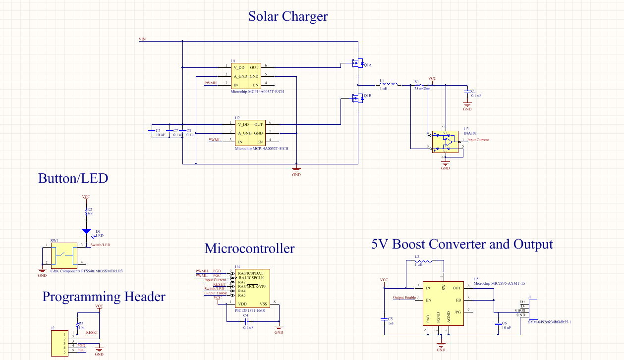
Circuit Design:
At 21 components, this is definitely one of my simpler designs.
This circuit contains:
- A PIC12 microcontroller, with 8 pins. This little guy is pushed to its limit, with some pins getting multiple uses!
- A programming header for the PIC
- A button and LED. Since I'm short on pins, these guys have to share, with the side effect that pushing the button will turn on the LED. The LED is to double as a make-shift flashlight.
- A 5V boost converter IC. In the spirit of "keep it simple", I let an IC do the work of generating 5 V from the battery.
- A custom synchronous buck converter. This is easily the trickiest part. I intend to implement MPPT, so measuring the current from the converter is a must. Due to the low voltages/powers involved, a boot-strap high-side NFET driver was deemed infeasible. Therefore, a PFET is used for the high-side gate, sacrificing low on-resistance for simpler and more efficient gate drivers.
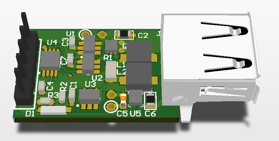
PCB Design
I designed the circuit and PCB in Altium CircuitMaker, my hobby tool of choice. I hold Altium as the gold standard of user interface, and once you've gotten used to it it's hard to use anything else.
The first prototype is just slightly over the One Square Inch requirements at 1.1 inch, which helps the USB port have more mechanical support. I cut it down a touch to fit the rules of the competition, and now the dimensions are 1.000 by 0.665 inches.
This is a two layer board with all the components on one side (except the button, which is on the back so that it's reachable). This circuit has a job to do, so no frills or fancy art, yet CircuitMaker renders it beautifully.
This CircuitMaker project can be accessed at https://workspace.circuitmaker.com/Projects/Details/Peter-Thompson-3/Simple-Solar-Charger
Next Steps
OSH Park just notified me that the boards are back from the fab! In a few days, I'll be able to build this up and test it out. I have a bit of code to write and an enclosure to draw up as well.