 Liam Lacey
-
1Cut/drill out the enclosure holes
- Cut/drill out the enclosure panel holes using either of the following templates - Annotated PNG or CAD DWG File.
- Cut/drill out a single 20mm hole of the rear of the enclosure (on the right side) for the USB connector.
The final result should look something like this.
-
2Solder wires to the controls
Solder wires to the following control pins:
- Joystick modules:
- X
- GND
- VCC
- Switched rotary encoders:
- Pin A (left pin of 3-set)
- Pin B (right pin of 3-set)
- Switch (either pin of the 2-set)
- GND 1 (centre pin of 3-set)
- GND 2 (remaining pin of the 2-set)
- Non-switch rotary encoders:
- Pin A (left pin of 3-set)
- Pin B (right pin of 3-set)
- GND (centre pin of 3-set)
- Push Buttons:
- Switch (either of the two pins)
- GND (the remaining pin)
- LCD:
- VCC
- GND
- CS
- RESET
- D/C
- SDI (MOSI)
- SCK
- LED
- SDO (MISO)
- Ignore any SD card or 'touch' pins (if present)
Wire colours - It is preferable to use black wire for all GND pins; red wire for all VCC pins; and all other colours for all other pins.
Wire lengths - Joystick VCC and all GND wires only need to be about 6cm as these wires will be daisy-chained between each control. All other wires need to be about 15cm so that they can comfortably connect to the microcontroller when inside the enclosure. However one joystick VCC and one GND wire instead need to be about 15cm too so that they can also connect to the microcontroller.
Wire types - For my build I used solid core wire for all wires here, however this proved slightly problematic when coming to trying to fit all electronics in the enclosure due to needing 'compress' the stripboard closer to the panel. Therefore I recommend the following:
- For wires between controls and the microcontroller, use stranded wire (for flexibility)
- For the VCC and GND wires daisy-chained between the controls, use solid core wire
- Joystick modules:
-
3Mount controls to the enclosure panel
Mount all controls to the enclosure panel in the following way:
- Joystick modules - for each module:
- insert a 12mm M3 screw into each of the 4 x 3.5mm holes from the top of the panel
- attach 2 M3 hex nuts to each of the 4 screws, tightening the screw to the panel
- attach the joystick module to the screws with the connection pins orientated towards the front of the enclosure
- attach a third hex nut to each of the four screws, tightening the joystick module to the panel
- The final result should look something like this.
- LCD:
- insert a 12mm M3 screw into each of the 4 x 3.5mm holes from the top of the panel
- attach 1 M3 hex nuts to each of the 4 screws, tightening the screw to the panel
- attach the LCD module to the screws with the connection pins on the left hand side when looking from the top of the panel
- attach a second hex nut to each of the four screws, tightening the LCD module to the panel
- Rotary encoders:
- Use the provided washer and hex nut to mount the encoders to the panel, placing the washer on the top of the panel with nut being placed over this. The encoder can be position at any angle, though having the connection pins facing the left and d right sides (as opposed to the front and back sides) makes it slightly easier to connect the wires to the microcontroller.
- Push Buttons:
- Use the provided washer and hex nut to mount the buttons to the panel, placing the washer on the bottom of the panel with nut being placed over this. The button can be position at any angle.
The final result should look something like this.
- Joystick modules - for each module:
-
4Attach the Teensy board to the Stripboard
Follow the following steps using the below photos as a guide:
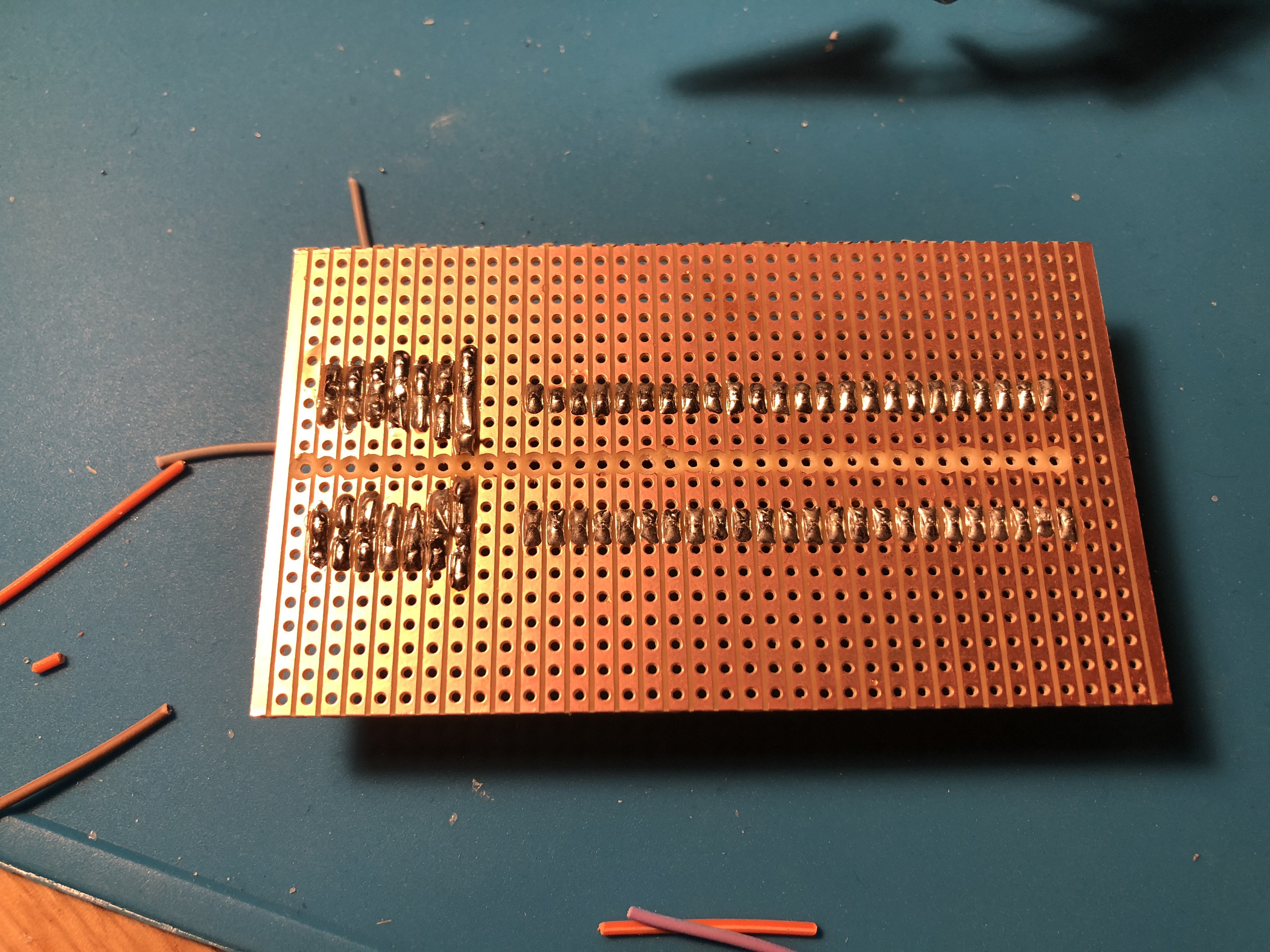
- Cut a piece of stripboard to a size that has 36 strips/tracks that are 21 holes long.
- Cut all 36 tracks in half (making 72 individual tracks).
- Solder the IC socket to the stripboard at one edge (e.g. tracks 1-24) with the two rows of pins either size of the central cut.
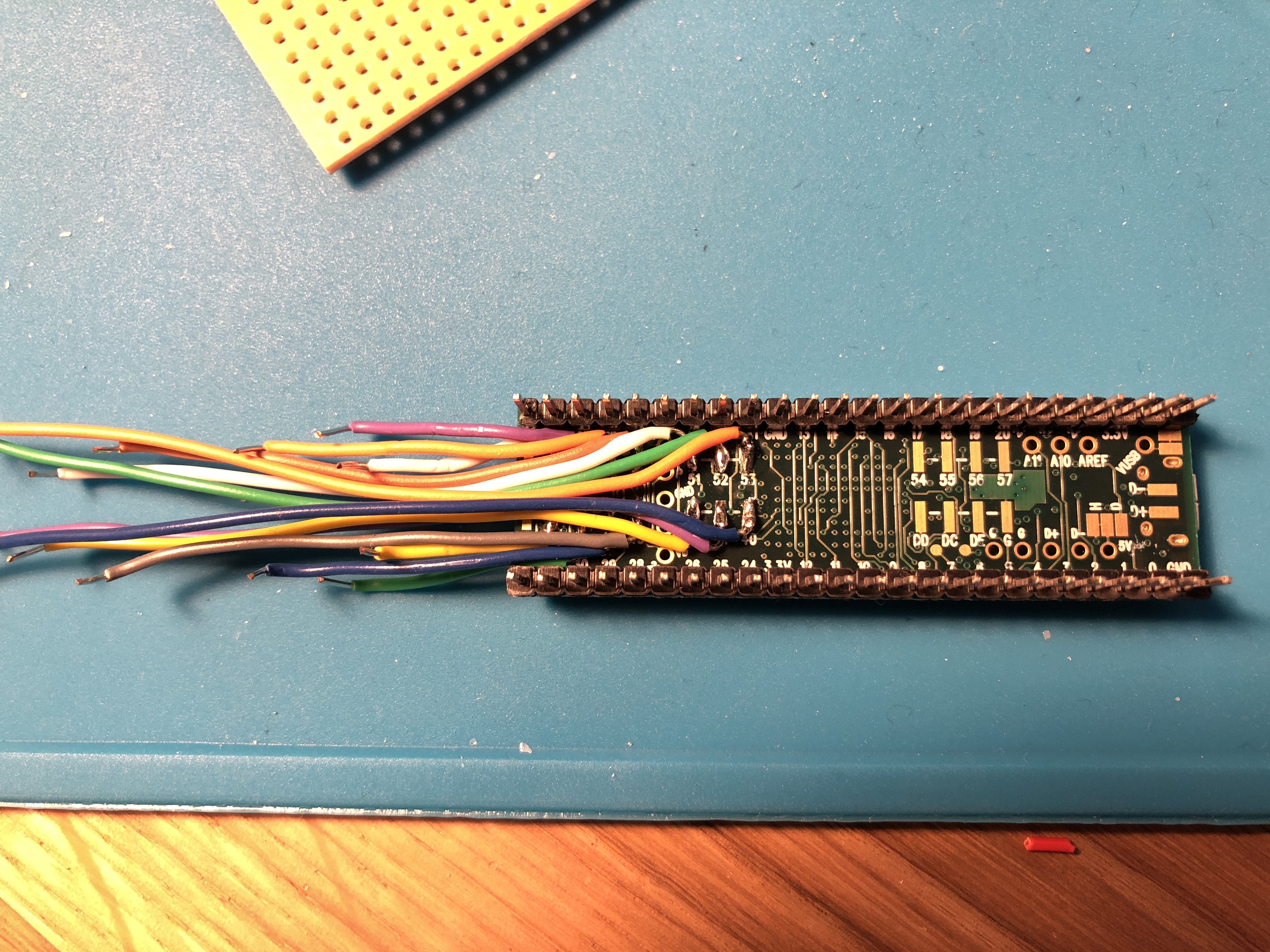
- Solder 14 short wires to surface mount pins 40-53 on the underside of the teensy board.
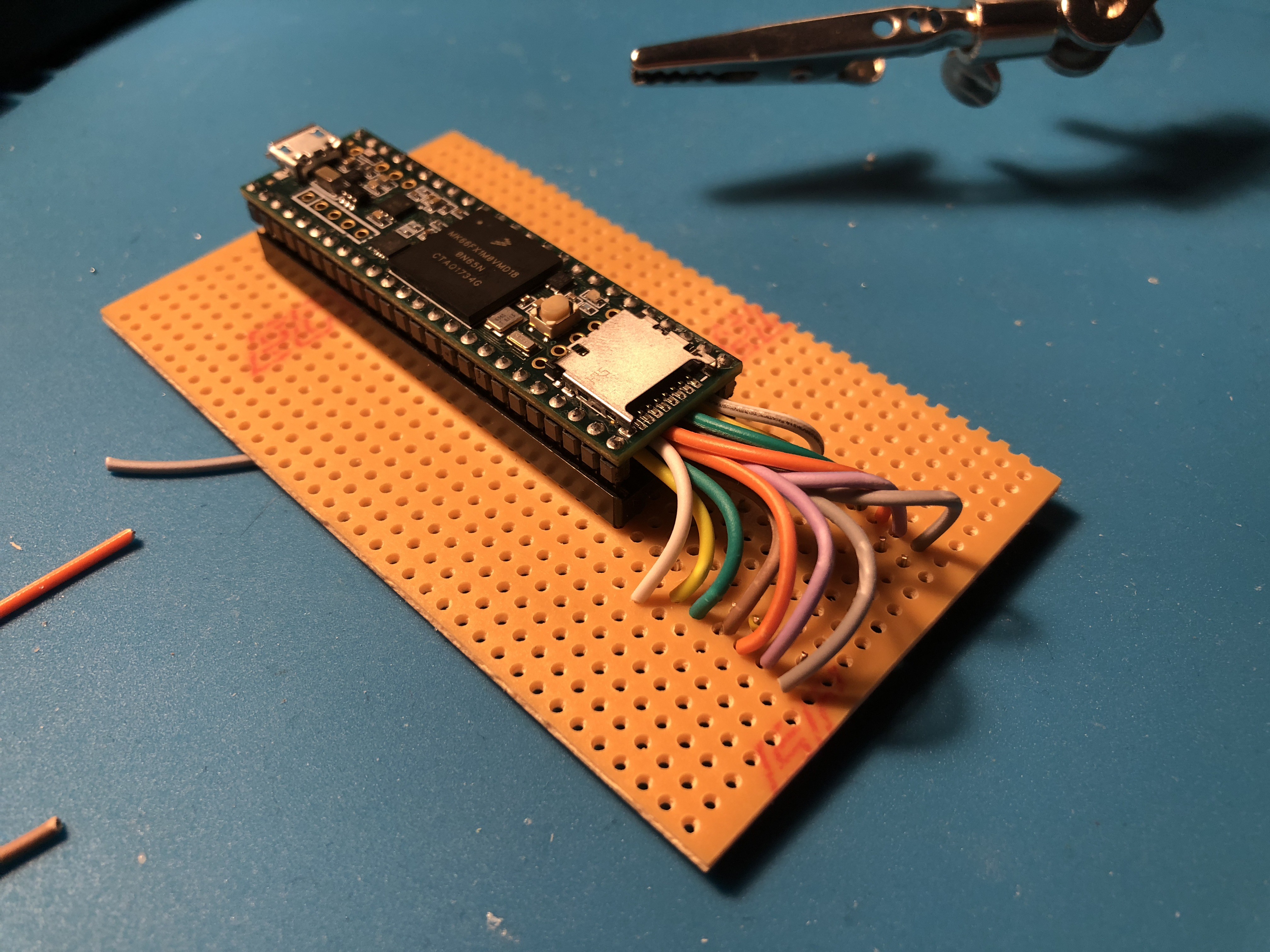
- Place the Teensy into the IC socket with the USB port on the edge of the stripboard.
- Solder each of the wires attached to the Teensy surface mount pins to their own tracks on the stripboard.
![]()
![]()
![]()
-
5Connect the controls to the Stripboard
- Solder the GND wire from each control to the GND pin of a neighbouring control, daisy-chaining all GND's together until you're left with just the longer GND wire (to be connected to the stripboard).
- Solder the VCC wire from each joystick to the VCC pin of a neighbouring joystick, daisy-chaining all joystick VCC's together until you're left with just the longer VCC wire (to be connected to the stripboard).
- At this point your should have something that looks similar to this but with the LCD also connected.
- With the underside of the panel facing up, place the stripboard central on the panel orientated so that the Teensy is facing the underside of the panel and the Teensy USB port is on the left hand side.
- Connect the rest of the wires to the stripboard as shown in the schematic. The GND wires can go to any of the GND pins/tracks, and the joystick VCC wire can go to any of the 3.3V pins/tracks.
- The final result should look similar to this and this.
-
6Connect and mount the USB socket / cable
- Cut off the header from the end of the Bulgin USB socket cable
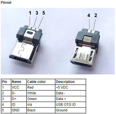
- Solder the 5 wires to the micro-USB plug as shown in the pinout photo below, where the braid / shield wire (the thicker black wire) connects to 5 / GND and nothing connects to 4 / ID.
- The modified USB socket / cable should look something like this.
- Attach the USB socket / cable to the hole in the rear panel of the enclosure using the provided nut.
![]()
-
7Downloaded needed software and libraries
Download and install (using the provided instructions in the links) the following software and libraries:
- Arduino IDE
- Teensyduino software add-on for Arduino IDE
- Optimized ILI9341 TFT Library for Arduino
-
8Program the Teensy board
- Connect the Teensy board to your computer. If it is a brand new Teensy the onboard LED may now be flashing.
- Download the project's GitHub repository
- Launch the Code/TurnadoController/TurnadoController.ino file with the Arduino IDE
- Go to Tools -> Board and select 'Teensy 3.6'. If you cannot see the Teensy board section go back and make sure you correctly installed Teensyduino.
- Go to Tools -> USB Type and select ‘MIDI’.
- Compile the code - Go to Sketch -> Verify/Compile, or instead just click on the tick icon on Arduino’s toolbar.
- If no errors appear in the console pane at the bottom, the Teensy software window should pop up.
- As stated in the Teensy software window, press the button on the Teensy board to put it into Program mode. The LED should no longer be flashing. You should only need to do this step if programming the Teensy board for the first time.
- Upload the code to the Teensy board - In the Arduino software go to Sketch -> Upload, or instead just click on the arrow icon on Arduino’s toolbar.
- If the upload is successful the Teensy software will show a progress bar followed by ‘Reboot OK’, and no errors will appear in the Arduino console pane.
- To verify that the upload worked and the Teensy board has been successfully programmed, the LCD on the controller should now be displaying a set of sliders and text.
-
9Put the enclosure together
- Connect and screw together the top, front, rear and sides of the enclosure, leaving the enclosure open from the bottom.
- Connect the micro-USB plug to the Teensy board's micro-USB socket
- Cover the inside of the bottom panel of the enclosure in an insulate material (e.g. strips of electrical tape) to prevent possible short circuits from the stripboard resting on it.
- Connect and screw the bottom panel to the enclosure.
-
10Set the default controller settings
Power on the controller, and using the LCD and the three LCD encoders configure the controller to the following default settings:
- Global -> Channel - 1
- [All controls] -> Channel - Global
- Knob1 -> CC Num - 1
- Knob2 -> CC Num - 2
- Knob3 -> CC Num - 3
- Knob4 -> CC Num - 4
- Knob5 -> CC Num - 5
- Knob6 -> CC Num - 6
- Knob7 -> CC Num - 7
- Knob8 -> CC Num - 8
- Dictator -> CC Num - 9
- Mix -> CC Num - 10
- Random -> CC Num - 11
- Preset -> 1st Prgm - 0
Turnado Hardware MIDI Controller
The development of a dedicated hardware MIDI controller for the Turnado audio FX software plugin.
Discussions
Become a Hackaday.io Member
Create an account to leave a comment. Already have an account? Log In.