Liam Lacey
-
Submitting for the Finals
10/21/2018 at 13:44 • 0 commentsI’m thrilled that this project has been chosen as one of the top 20 projects of the musical instrument challenge, and that it is now going into the finals of the 2018 Hackaday Prize!
Therefore over the past couple of days I’ve been busily finishing off the last few requirements of the project:
- The contest entry video (embedded below for convenience)
- Full build instructions
- Complete Bill Of Materials from UK Suppliers document
Enjoy!
-
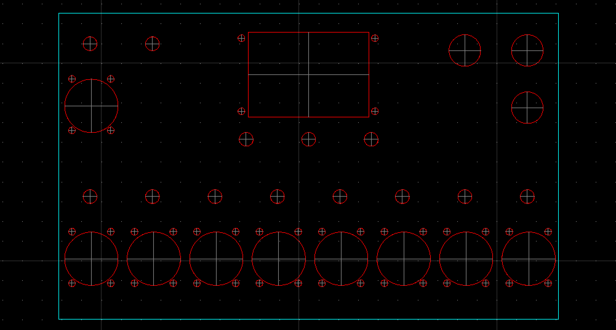
Panel CAD Drawing
10/18/2018 at 18:08 • 0 commentsWith the help of my wonderful girlfriend, I've now got a DWG CAD file of the panel design, stating the positions and sizes of all holes that need to be made. Below is a preview, but the file can be found in the Files section of this project and in the project's git repository.
![]()
-
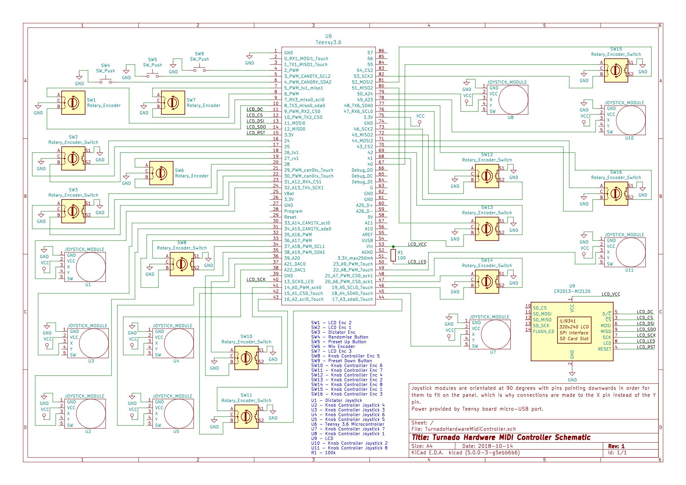
Project Schematic
10/14/2018 at 08:54 • 0 commentsHere is the the schematic for the project drawn using KiCad:
https://cdn.hackaday.io/files/1607926879324928/TurnadoHardwareMidiControllerSchematic.pdf
You can also find the .sch file in the project's GitHub repository.
It's the first time I've used EDA software to draw a schematic, and the first time I've drawn a schematic of any kind in a long time (other than using Fritzing every now and then), therefore I'm not sure if it's laid out in the optimum way. However it should tell you everything you need to know about how to wire up the circuit for this project if you wanted to give it ago yourself.
![]()
-
Demonstration Video
10/07/2018 at 17:27 • 0 commentsSix weeks ago this project was just an idea in my head; but after 2220 lines of code, 112 wires to solder, 67 enclosure holes to drill, and 1 broken microcontroller, the device is finally in a usable state that I can demonstrate!
Here is a video demonstrating the MIDI controller in use, where it is controlling two instances of the Turnado plugin to perform live audio manipulation/remixing of a set of audio loops (taken from one of my own tracks). Ableton Live is being used as the host software for the plugins, and a Novation Launchpad is being used to trigger the audio loops.
Unfortunately it's not easy to make out the realtime control feedback on the LCD in the above video, therefore here is a quick video showing the behaviour of the LCD when controlling the software parameters, or when the software parameters are controlled directly and send MIDI back to the device:
Enjoy!
-
Code Development
10/07/2018 at 17:10 • 0 commentsI've now got the Teensy firmware code to a point where the MIDI controller is working as intended and fully usable for controlling the Turnado software.
All software can be seen in the project's GitHub repository, and rather than trying to describe here how the software implementation works I've commented the code as much as possible to try and explain this.
The code I have written for this project is split over 13 files, where the Arduino/Teensy sketch code is split over 7 files (the .ino file and 6 .h files), with three classes (each split over a .h and .cpp file) that are used in the sketch.
These are the code files that make up the project's Teensy/Arduino project:
- TurnadoController.ino - The Teensy/Arduino sketch file. This file doesn't include much code other than includes to the sketches .h file, call's to 'setup' and 'update' functions within the .h files, and some global variables.
- Globals.h - This file includes global defines that are needed by many of the other files.
- PinAllocation.h - This file includes defines for the Teensy pin allocations for the project.
- Controls.h - This file includes all code relating to reading and processing the devices controls. This is one of the largest code files of the project.
- Lcd.h - This file includes all code related to the setup of and drawing on the LCD. This is another one of the largest code files of the project.
- MidiIO.h - This file includes all the code relating to MIDI input and output.
- Settings.h - This file includes all code relating to the device settings and reading from and writing to EEPROM.
- RotaryEncoder.h / RotaryEncoder.cpp - This class handles the processing of rotary encoder controls.
- SwitchControl.h / SwitchControl.cpp - This class handles the processing of push buttons / switches.
- ThumbJoystick.h / ThumbJoystick.cpp - This class handles the processing of thumb joysticks (current only Y axis, and X axis and switches aren't used in this project).
-
Attaching Controls to the Enclosure pt. 2
10/05/2018 at 17:18 • 0 commentsIn my first 'Attaching Controls to the Enclosure' log I ended by stating two things I had left to do in regards to the enclosure:
- Add a laser cut frame around the LCD to tidy up the messy panel cutting
- Attach a USB socket to the rear of enclosure
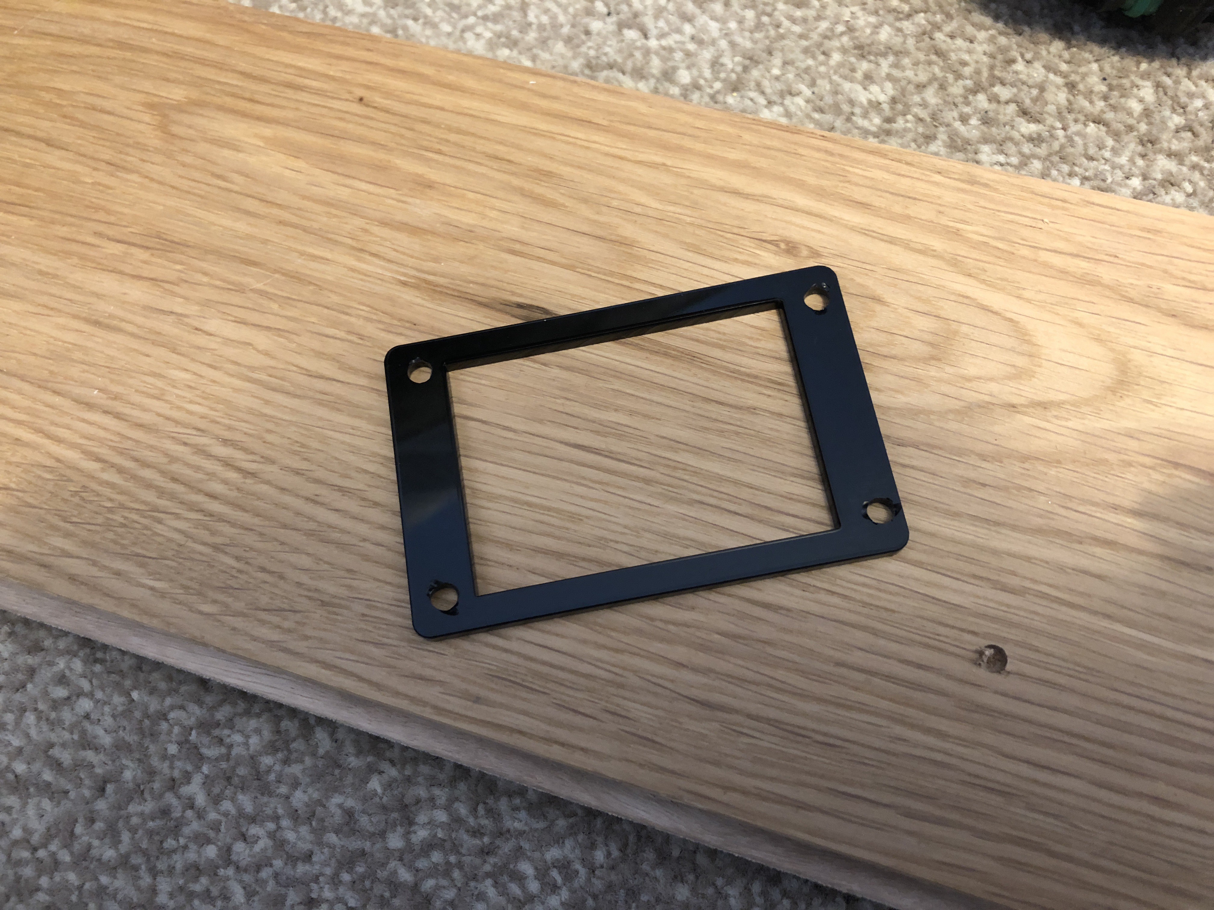
LCD Frame
I've now attached a 3mm black acrylic laser-cut frame around the LCD, attached to the enclosure using the LCD screws, and it's dramatically improved the look of the overall device.
See below for some photos (where the second photo is a 'before' shot)...
![]()
![]()
![]()
![]()
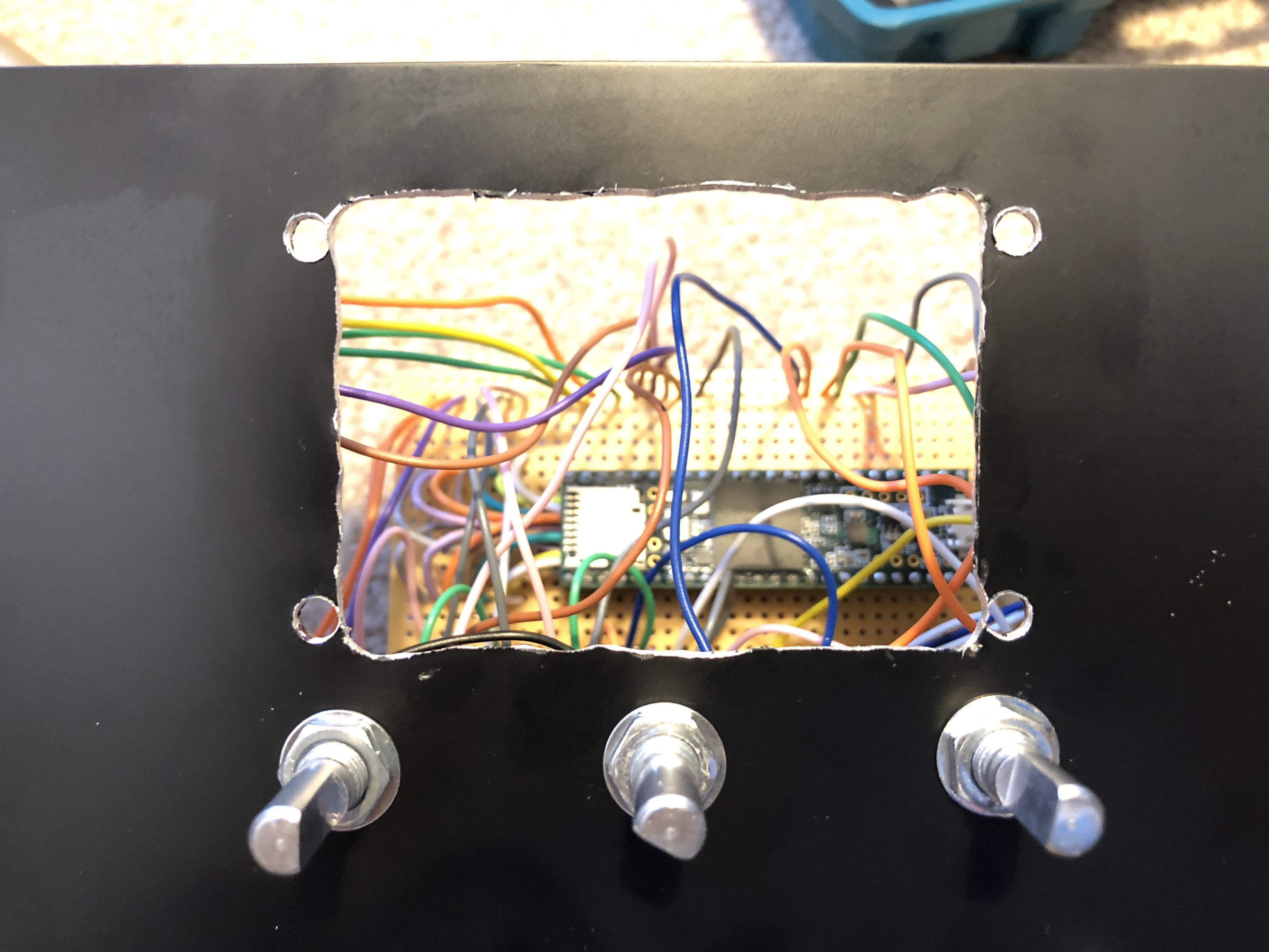
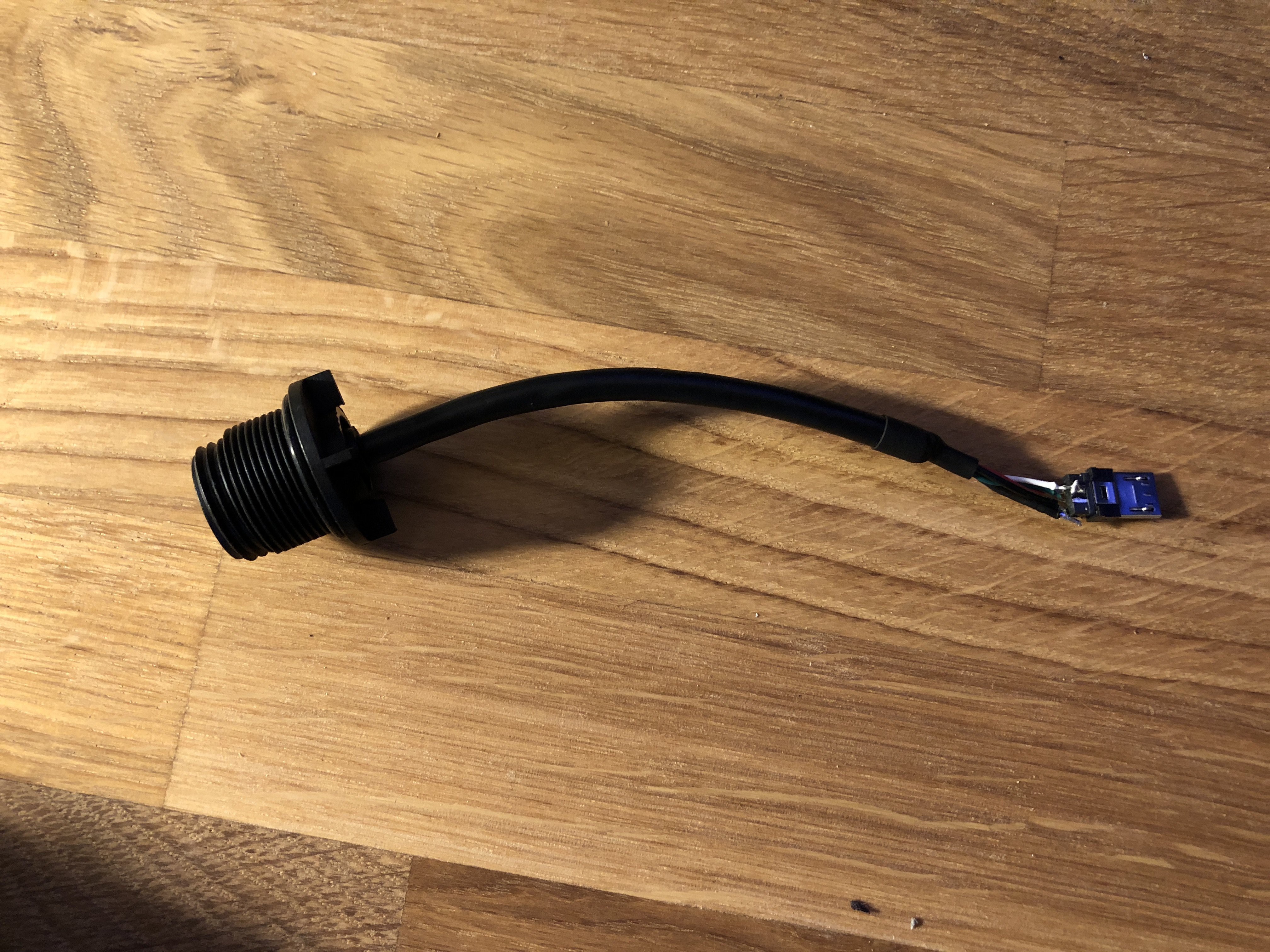
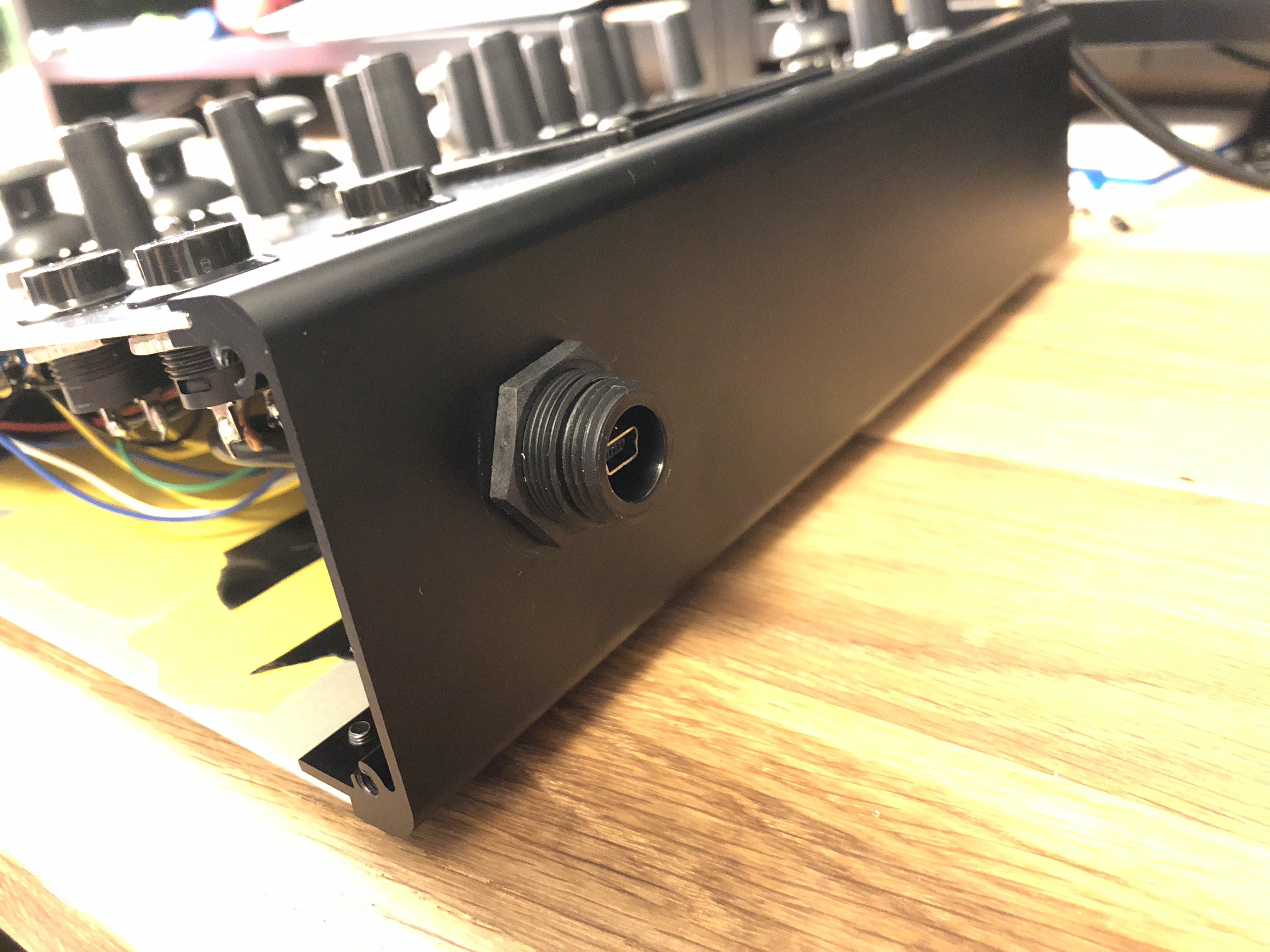
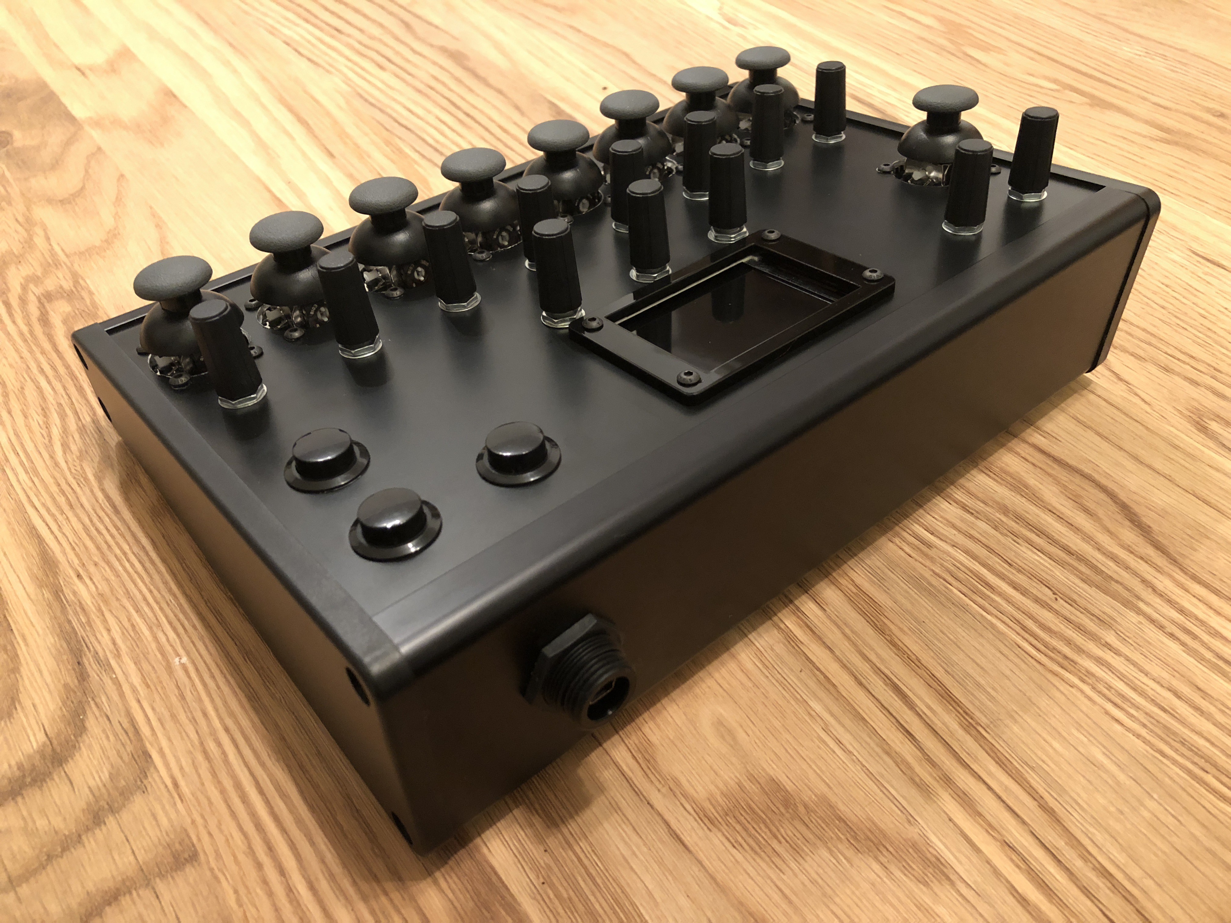
USB Socket
To allow the Teensy board's USB port to be accessible from the outside of the enclosure I've attached a Bulgin PX0446 Panel Mount USB connector/socket to the rear of the enclosure, where I've soldered a micro USB plug to the end if it's lead so that it can connect to the Teensy board. I'm not particularly happy about how much the socket protrudes from the surface of the enclosure, however this seems to be the only panel mountable USB socket available of it's kind. See below for photos:
![]()
![]()
![]()
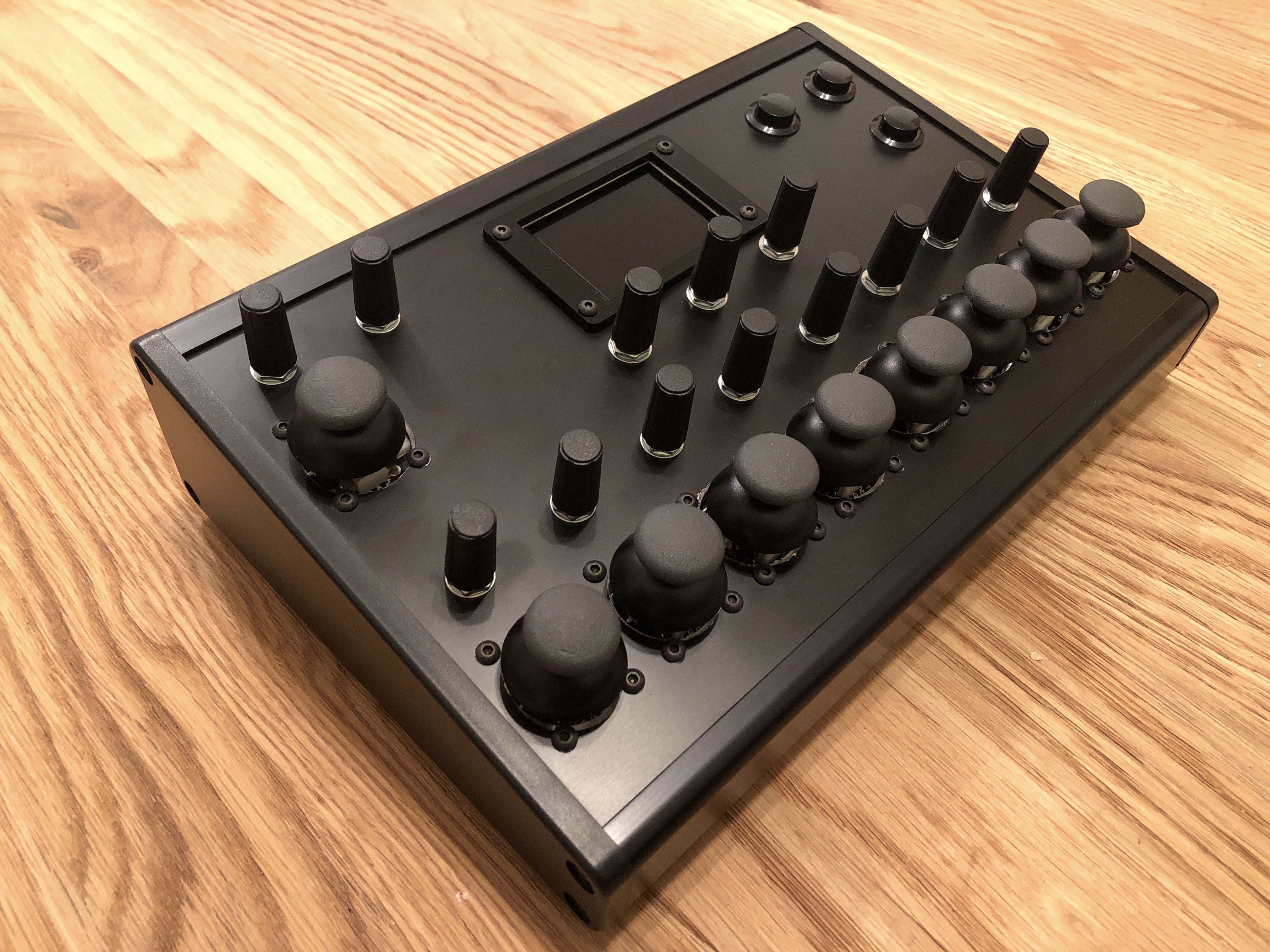
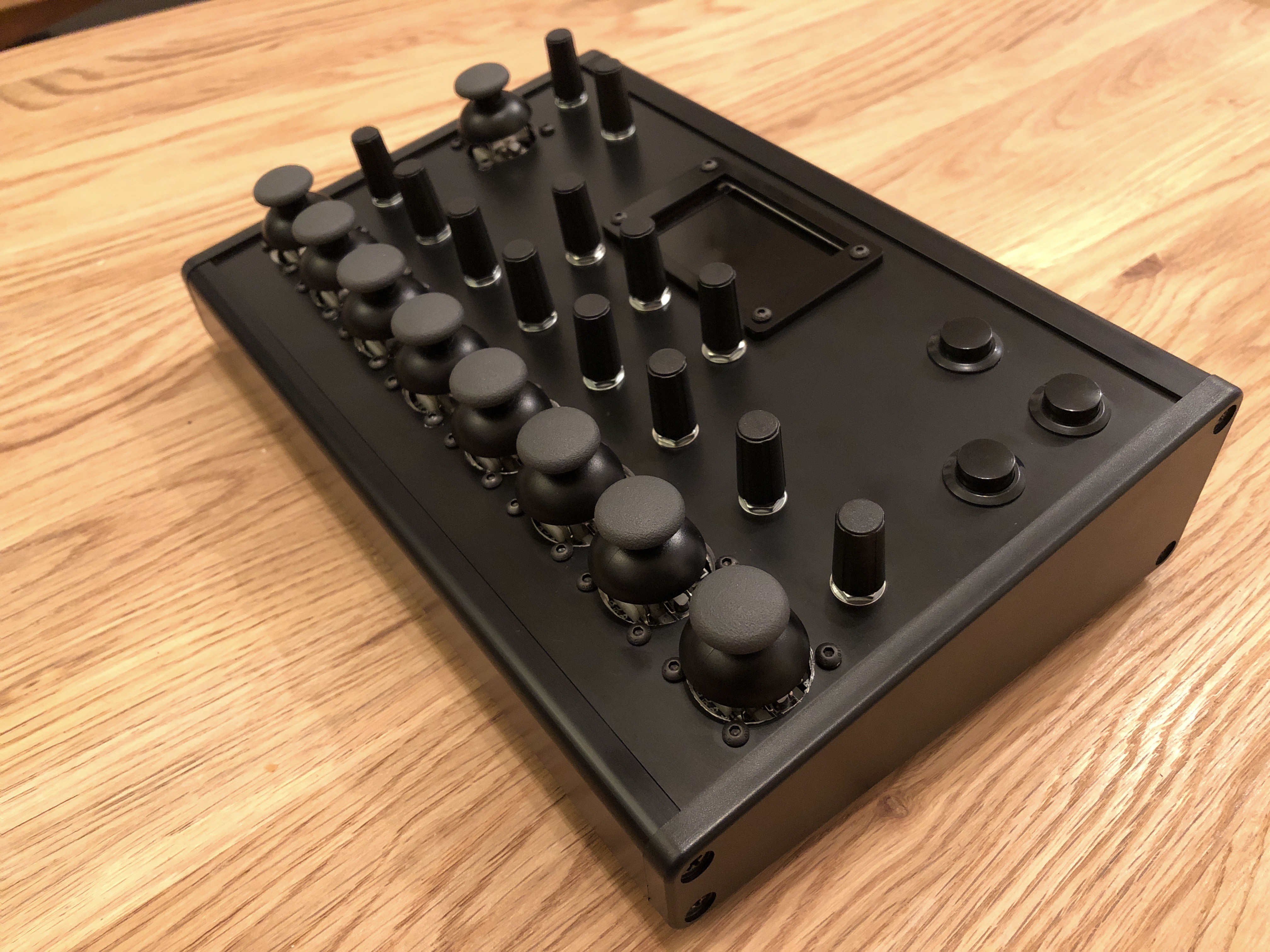
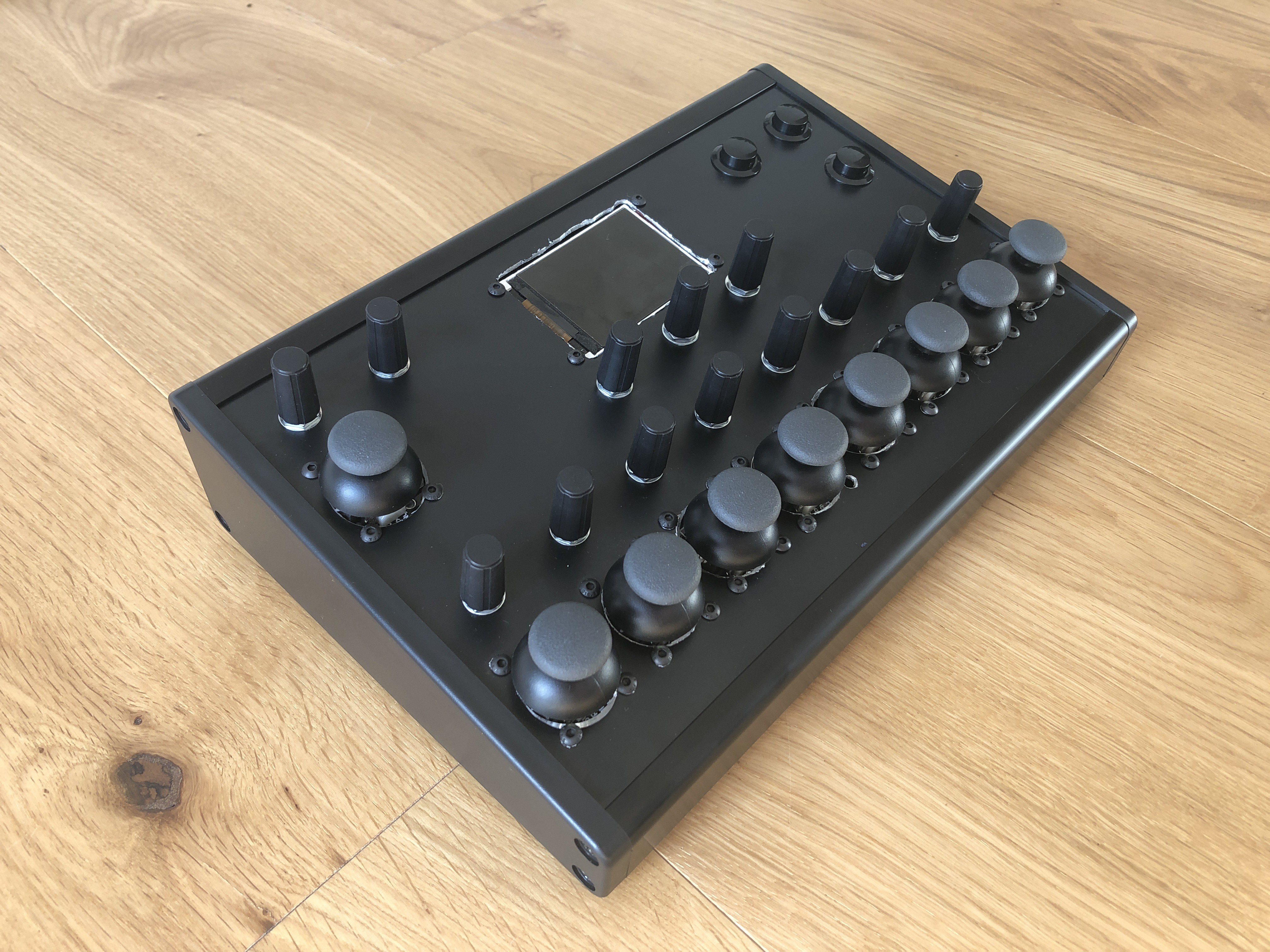
The Finished Enclosure
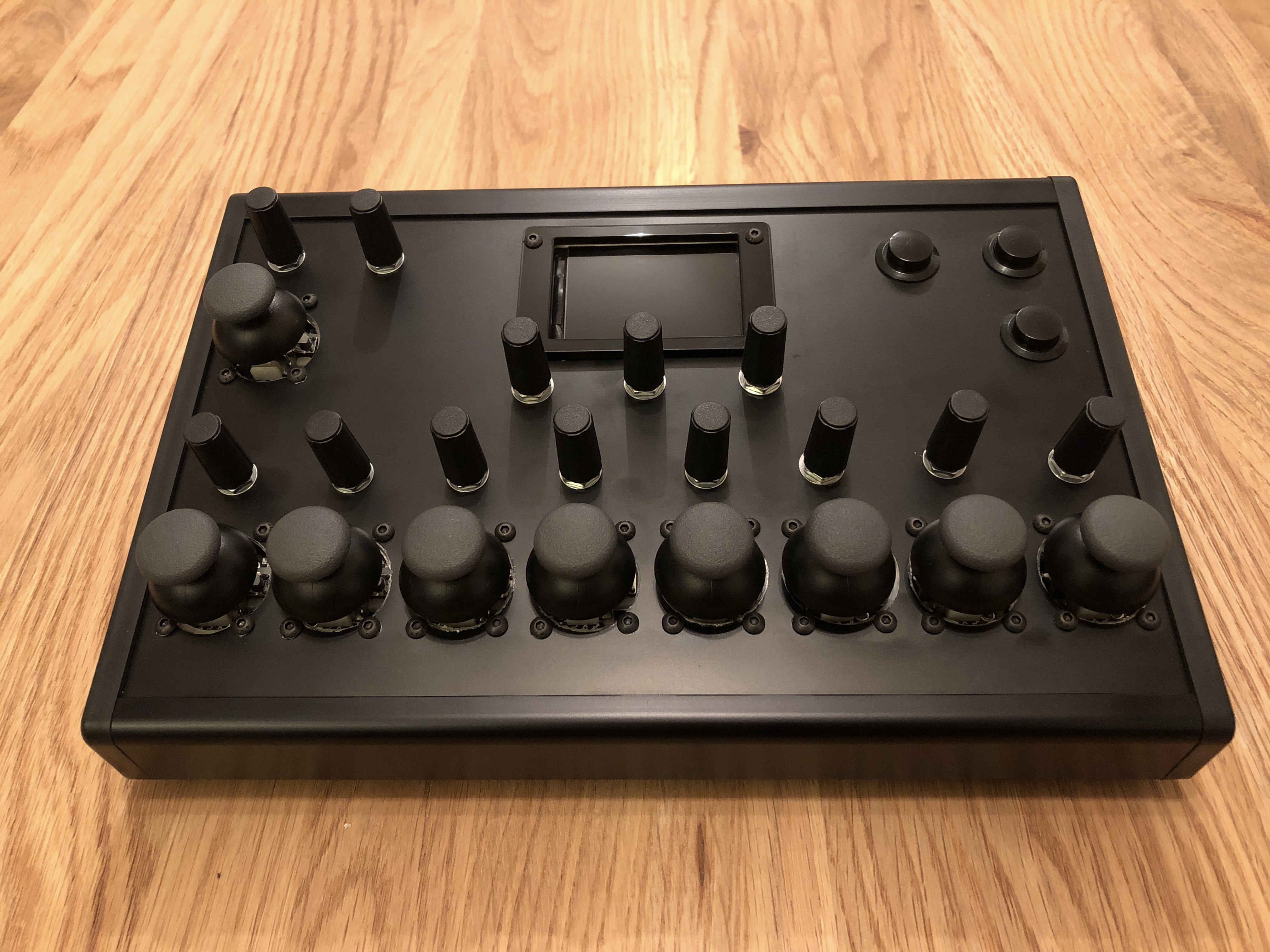
With these two parts done, the enclosure (and overall hardware) is now finished! I'm toying around with the idea of added a decal to the panel to label all controls, however I really like the clean minimal look of it without this. Here are some photos...
![]()
![]()
![]()
![]()
-
Building the Electronic Circuit
10/04/2018 at 07:22 • 0 commentsOver the past couple of weeks I've mainly been busy completing the electronic circuit for the device. All electronics have been done using wire and stripboard (rather than building a PCB), simply because this is what I feel most comfortable with.
Circuit Design
Other than needing a lot of wires to attach the controls to the Teensy microcontroller, the circuit is very simple and only requires 1 resistor (mainly thanks to the presence of the internal pullup resistors on the Teensy pins), and requires no other extra components. The main reason I chose to use a Teensy 3.6 over the smaller Teensy boards was so that all controls could be connected directly to the microcontroller without have to use multiplexers or shift registers. However as the Teensy 3.6 is probably overkill for this project in every other way, a Teensy 3.2 with some shift registers would be a more affordable option for building this device.
I will post a circuit diagram at a later date.
Teensy Pin Allocation
This device uses 53 pins of the microcontroller, leaving 6 spare digital pins and 3 spare analogue pins. I have specifically left pins 0 and 1 (RX1 and TX1) spare incase I want to add serial MIDI-DIN connections in the future.
The specific pin allocation I have chosen is based on the orientation of the Teensy in the enclosure and the position of the controls on the panel.
Click here to see the pin allocation.
Issues
Other than it taking a long time to solder all wires to all controls, the main issue I had was when soldering wires to the surface mount pins on the Teensy. On my first attempt I ended up accidentally pulling off a couple of the solder pads when trying to bend the wires into position, causing the Teensy to start behaving temperamentally (resulting in me needing to replace the Teensy board altogether). However after switch from solid core wire to stranded wire (which has more flexibility) I didn't have this problem again. I had considered using right-angle headers to access the surface mount pins, however this appears to be more suited for when using protoboard (rather than stripboard), which I personally don't like to use.
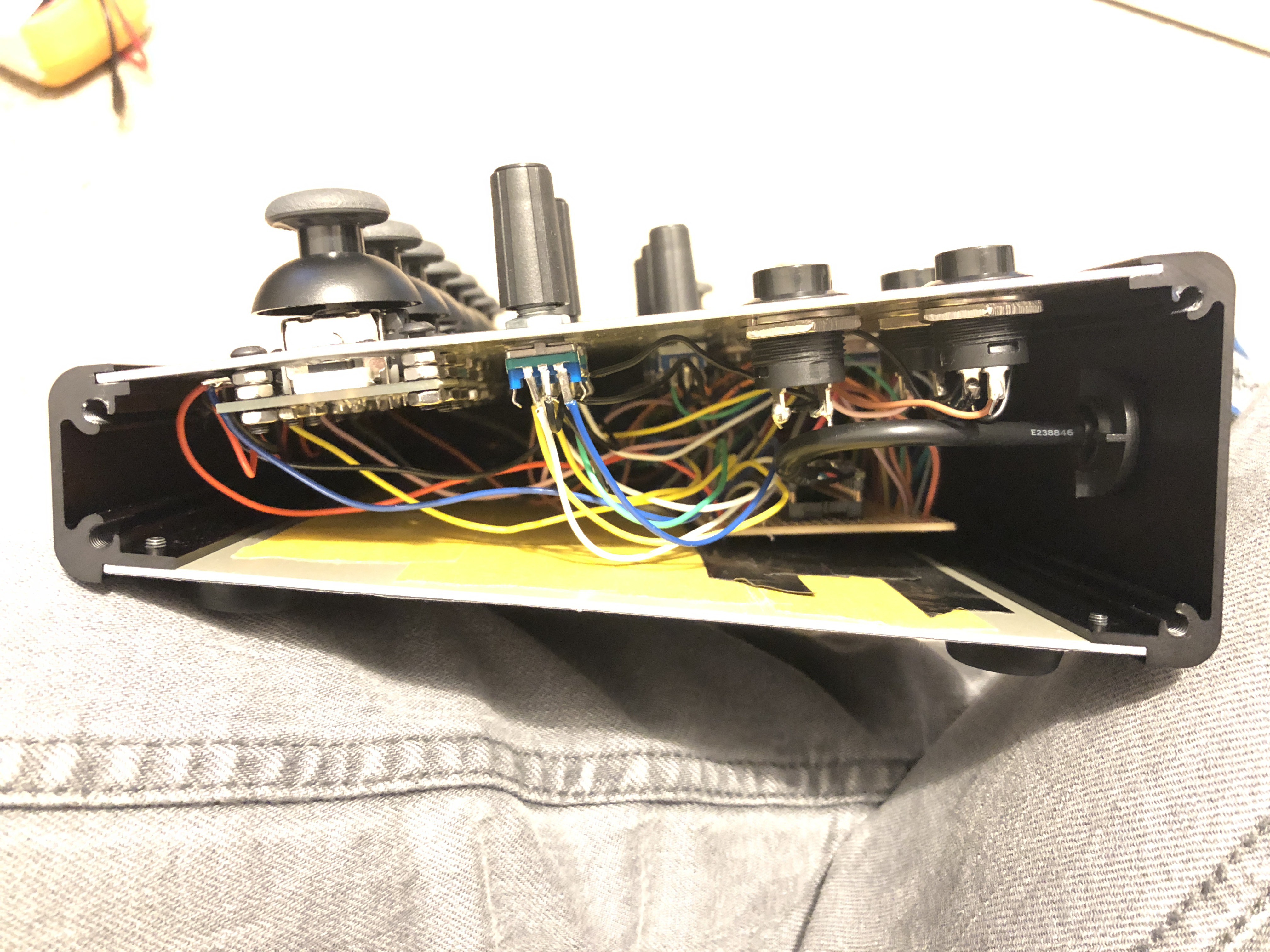
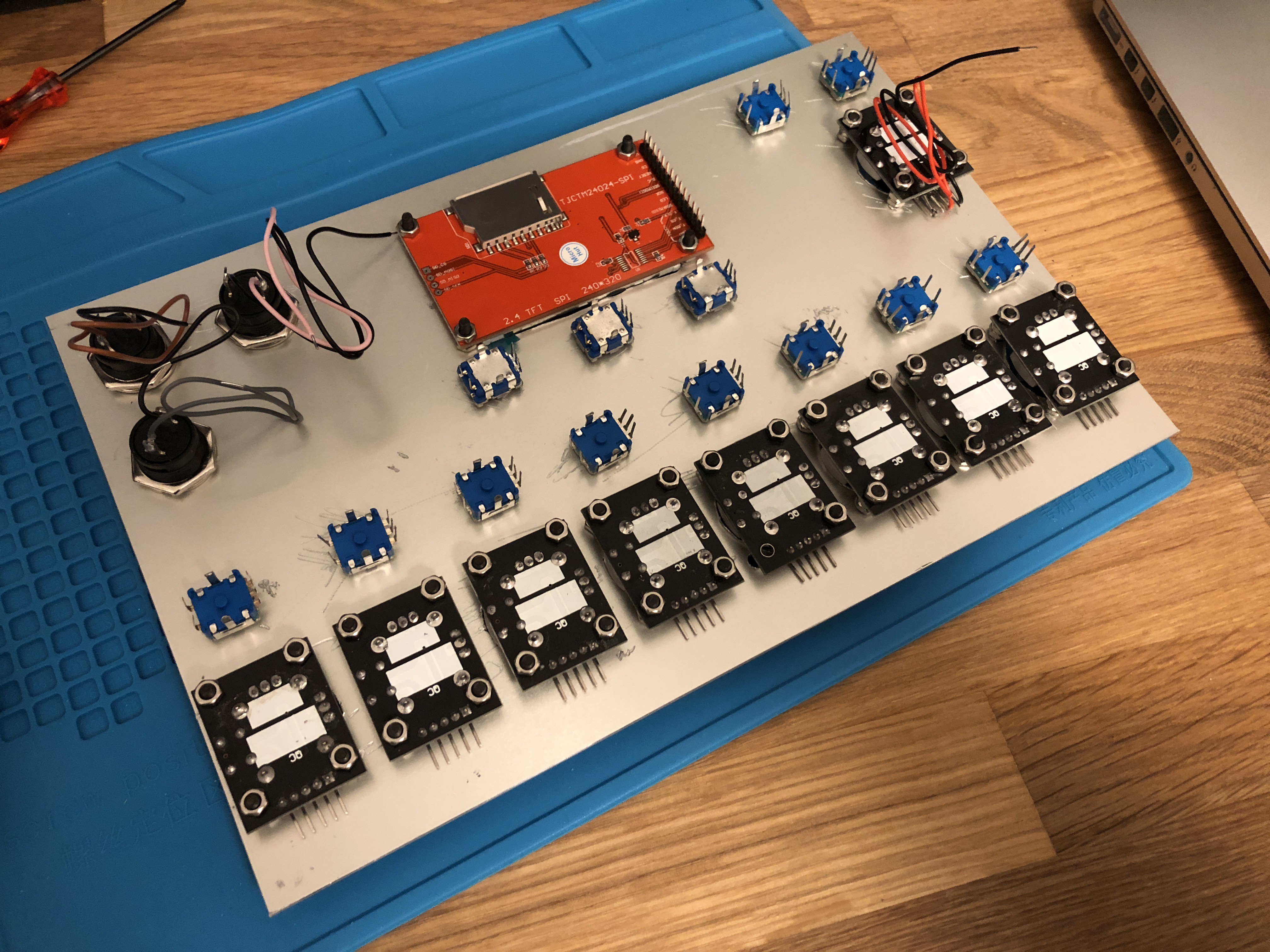
Photos
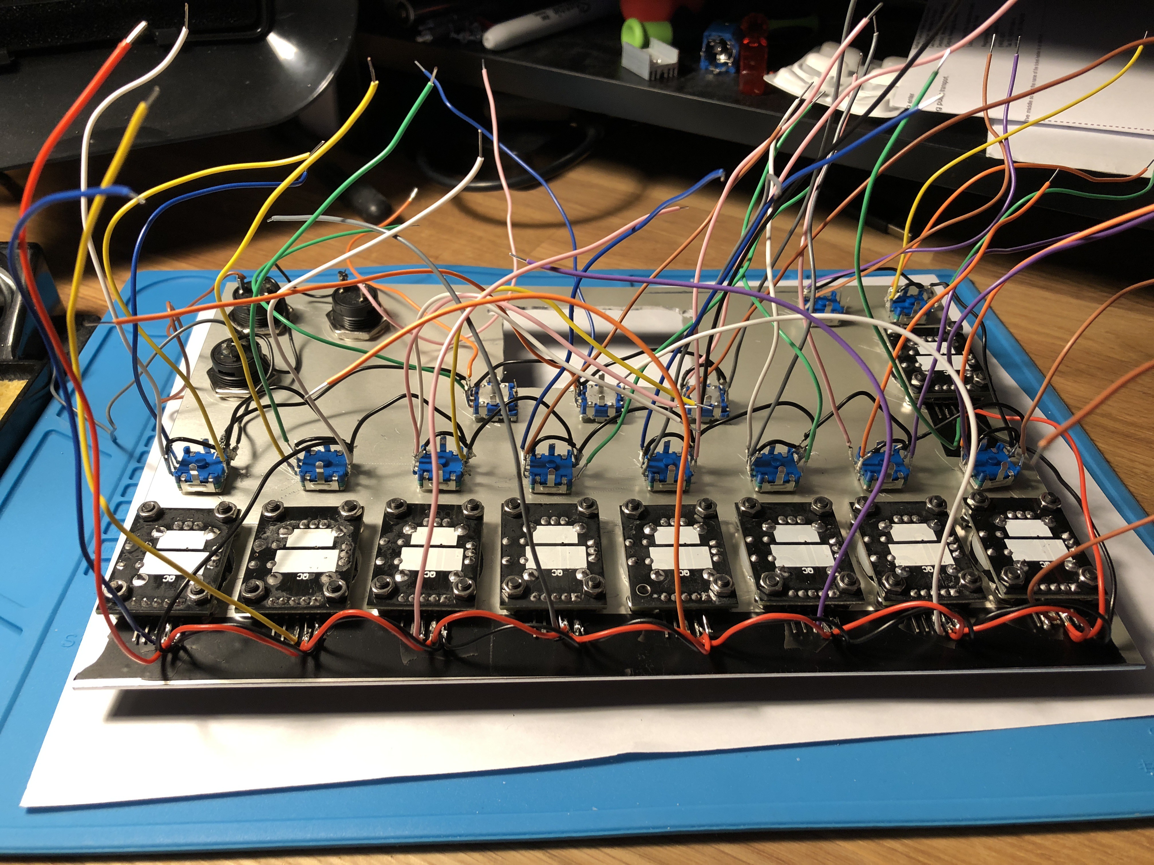
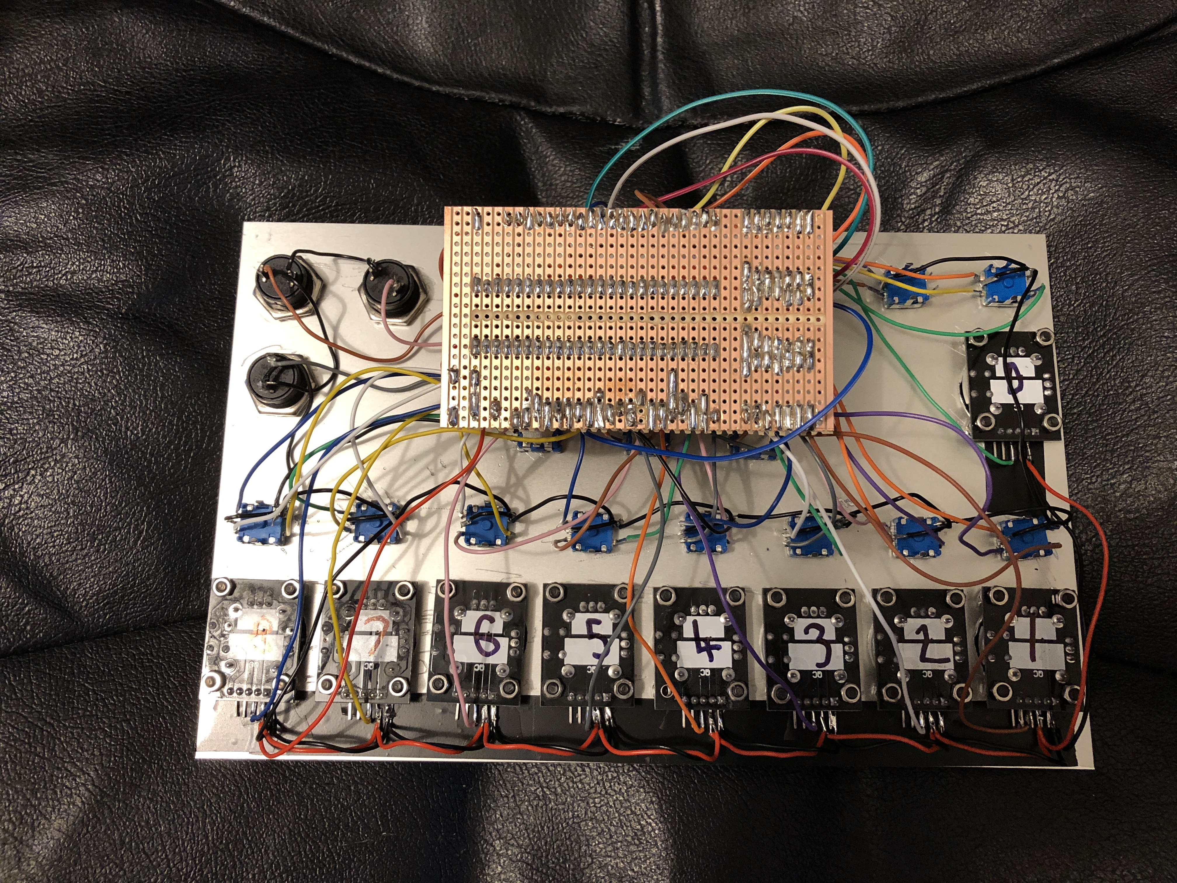
![]()
The panel control wires. GND and 3.3V wires are daisy-chained between controls.
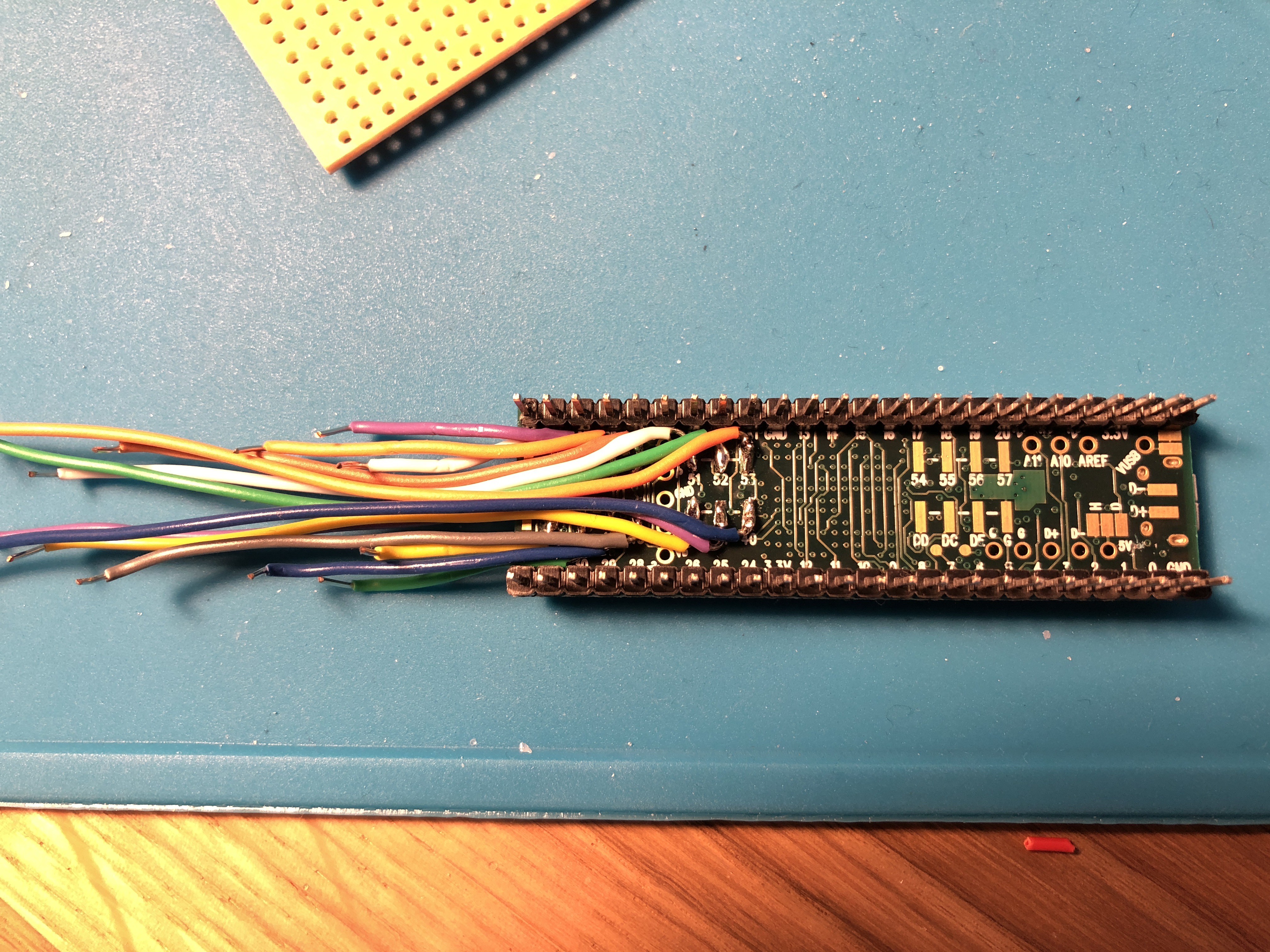
![]()
Wires soldered to the surface mount pins of the Teensy.
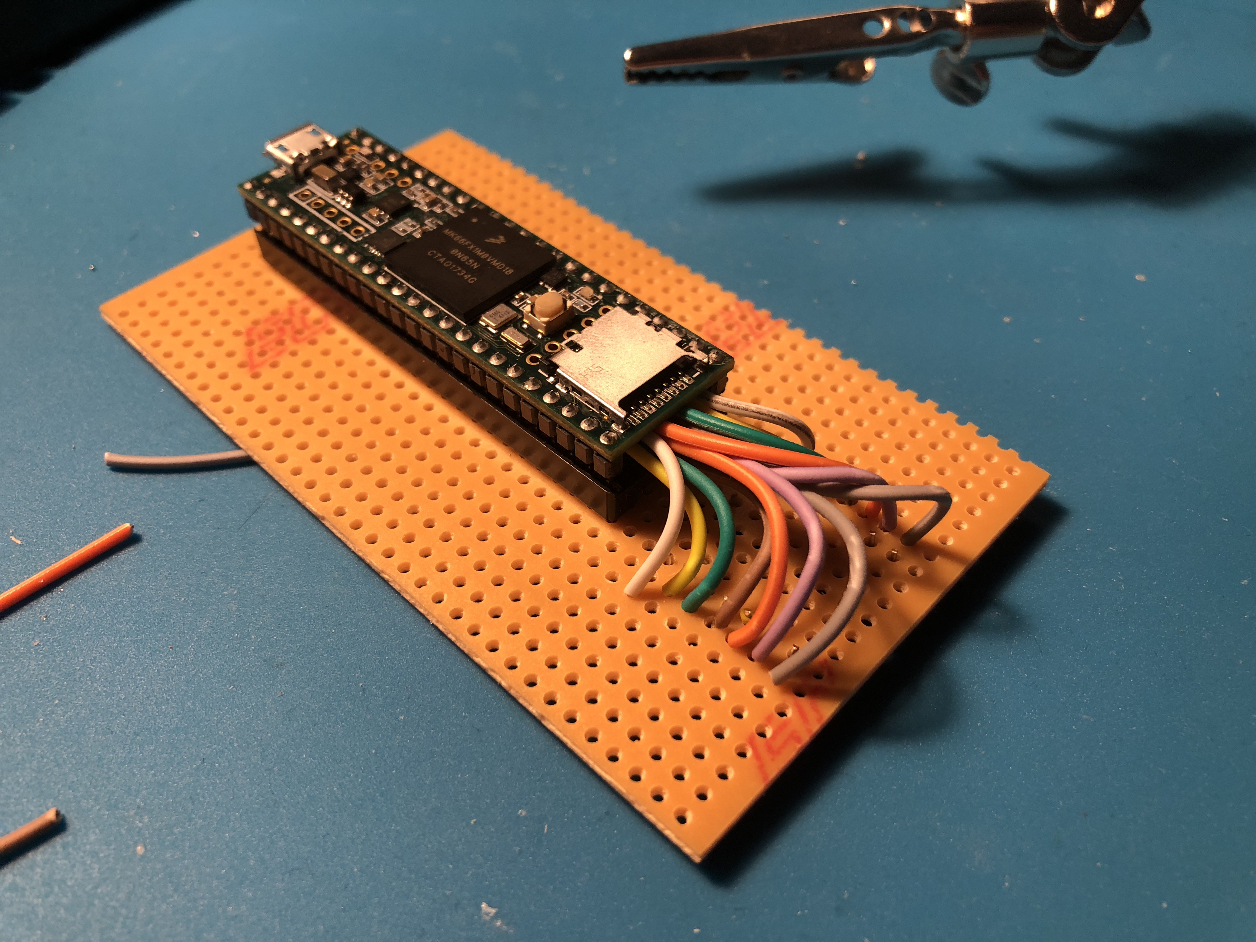
![]()
Teensy in a socket attached to stripboard, where the wires from the surface mount pins are attached to their own strips.
![]()
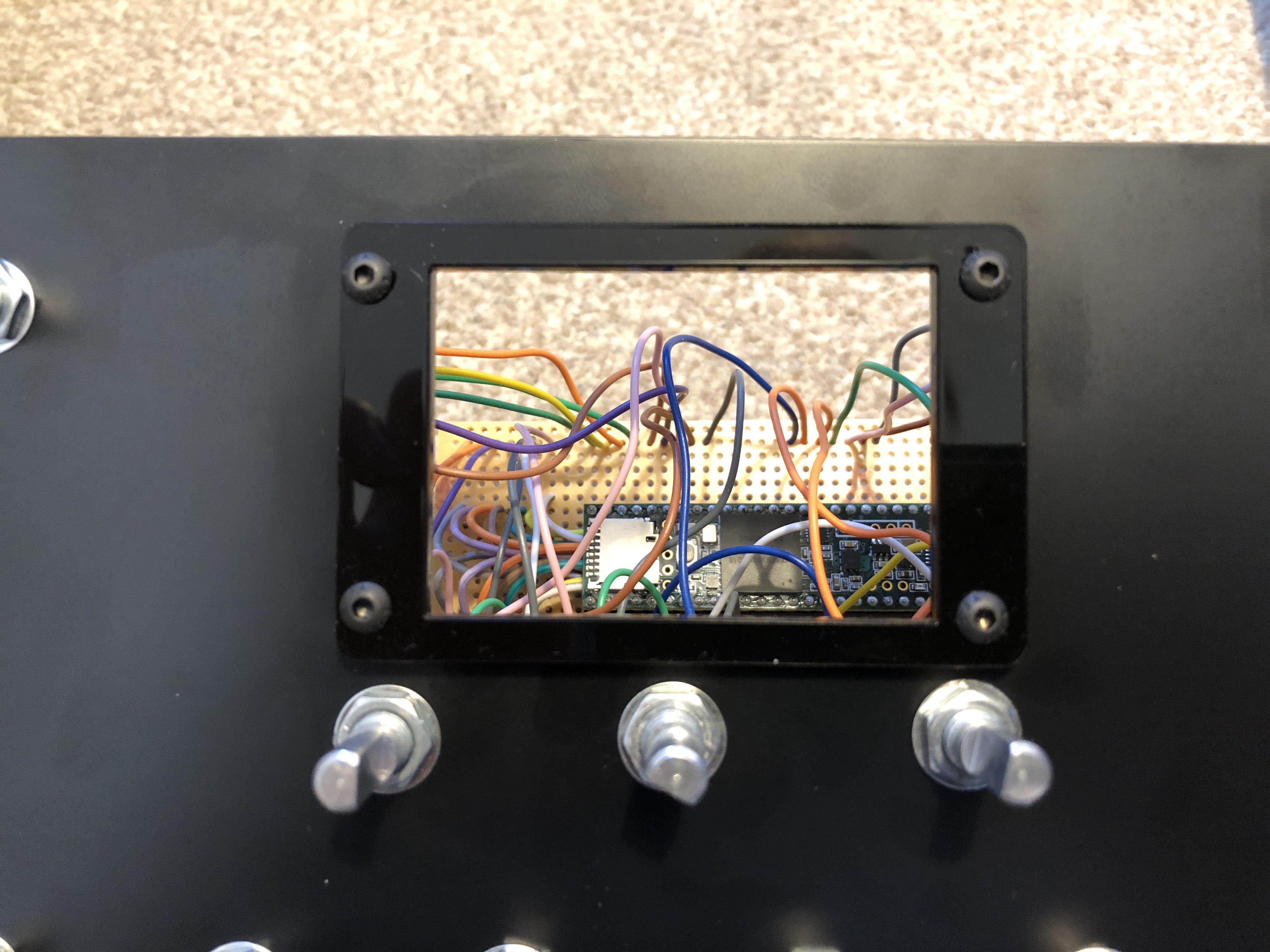
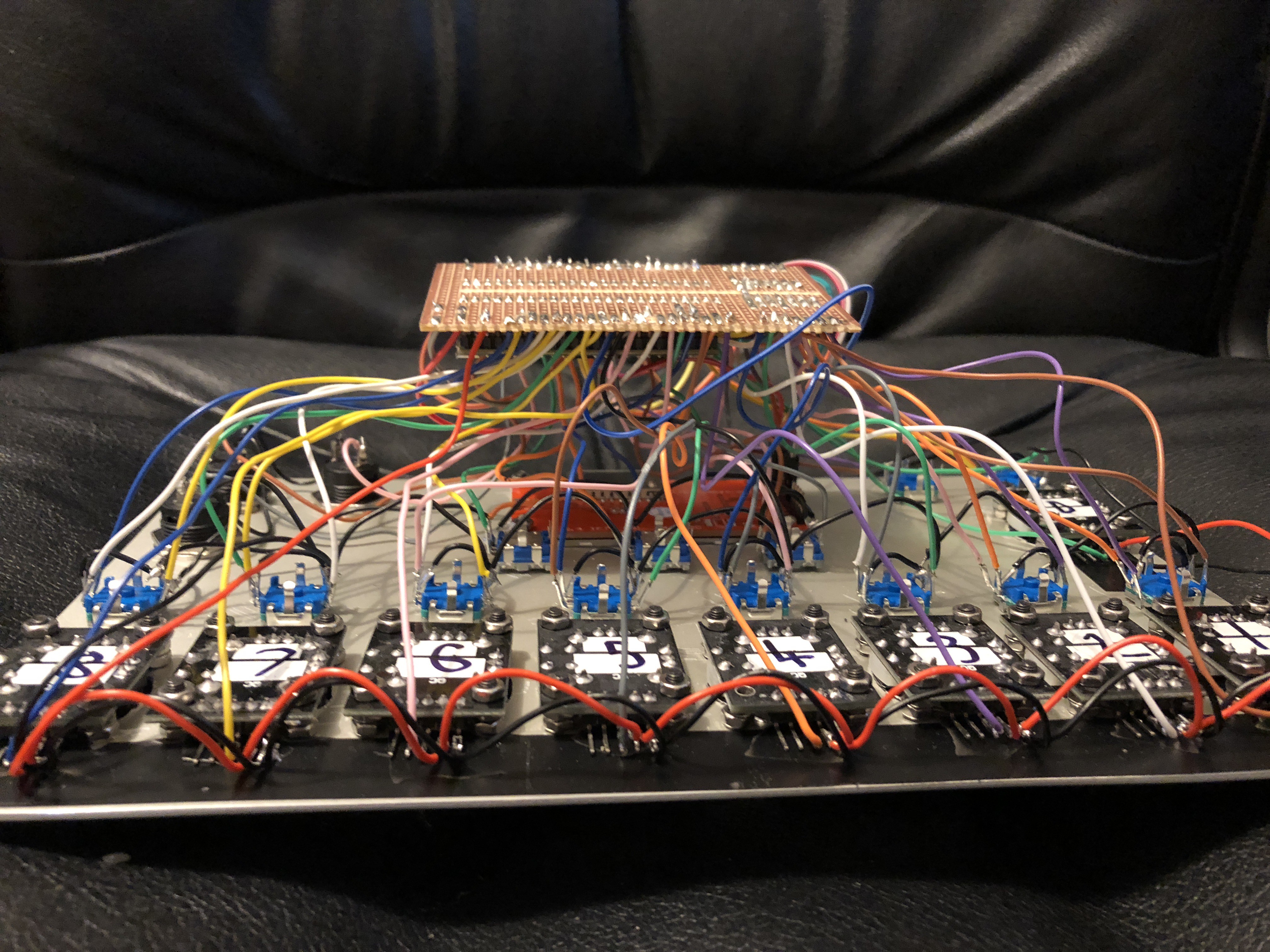
The completed electronics.
![]()
The mess of wires.
-
Attaching Controls to the Enclosure pt. 1
09/24/2018 at 09:25 • 0 commentsOver the past weekend I attached the majority of the controls to the enclosure, and the device is now starting to look like a working MIDI controller (from the outside anyway!).
Parts
These are the parts I've used:
- 13 x Rotary Encoders. The encoders I'm using are 20 click indented, and have a switch on them which the majority of them will use.
- 9 x Thumb Joysticks Development Modules. These come on their own PCB with mounting holes which make it easier to mount the joystick to the panel. These joysticks have a switch on them, but as mentioned in a previous log I won't be using them here.
- 3 x Black Momentary Push Buttons.
- 1 x 2.4" 320x240 TFT LCD with a ILI9341 controller chip.
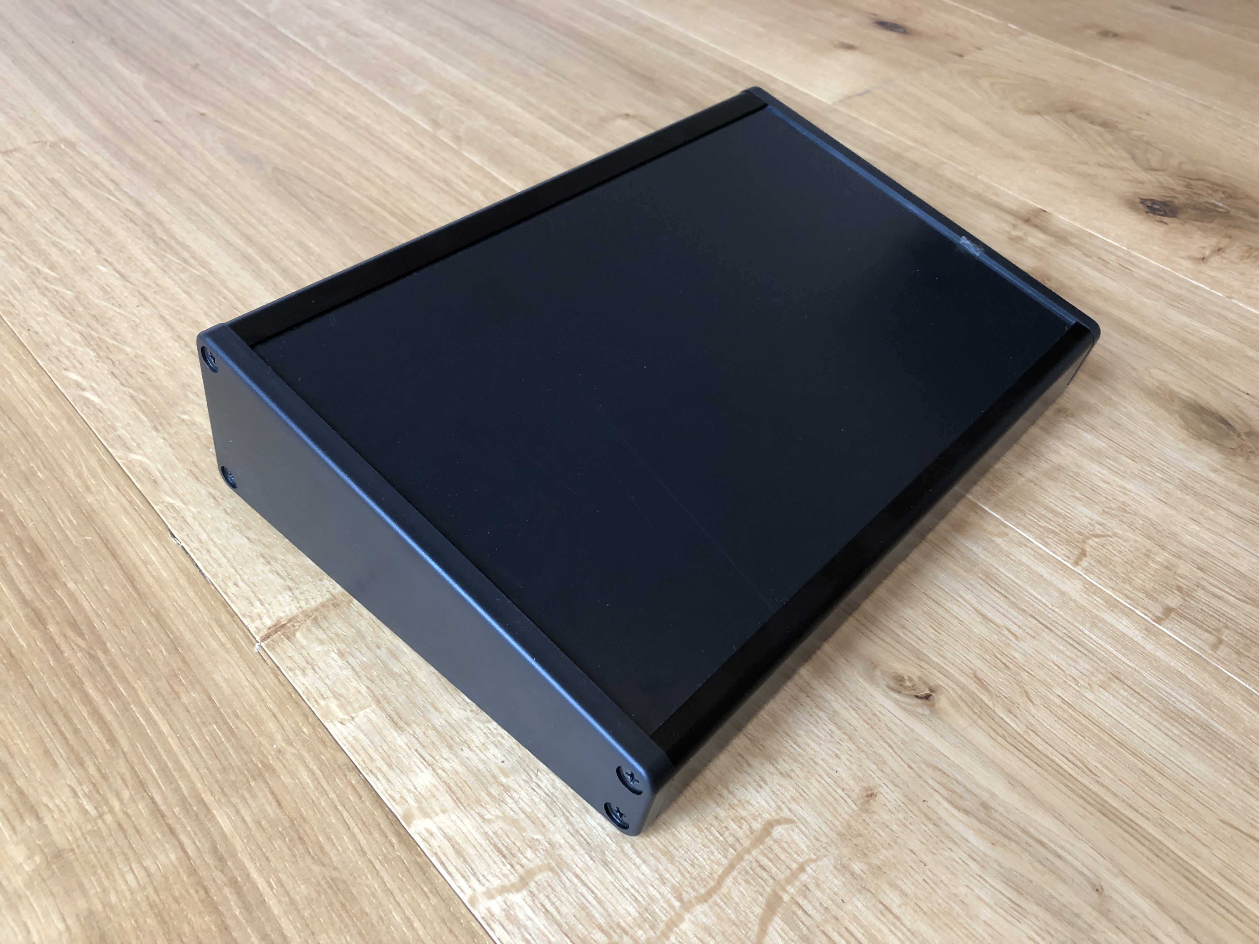
- 1 x Takachi Electric Industrial CF27-18BB sloped enclosure.
Enclosure Choice
I chose to use the Takachi Electric Industrial CF27-18BB enclosure for the following reasons:
- The sloped design of it should make the controller more usable
- It's almost the perfect size for the controller
- The panel faceplate can be easily removed from the frame, making it easier to drill holes in and makes it easily replaceable if needed.
- You can access the inside of the enclosure from either the left side, right side or bottom; this will be handy if needing to repair the device once all put together.
- Aluminium is more robust than plastic
- Comes in black
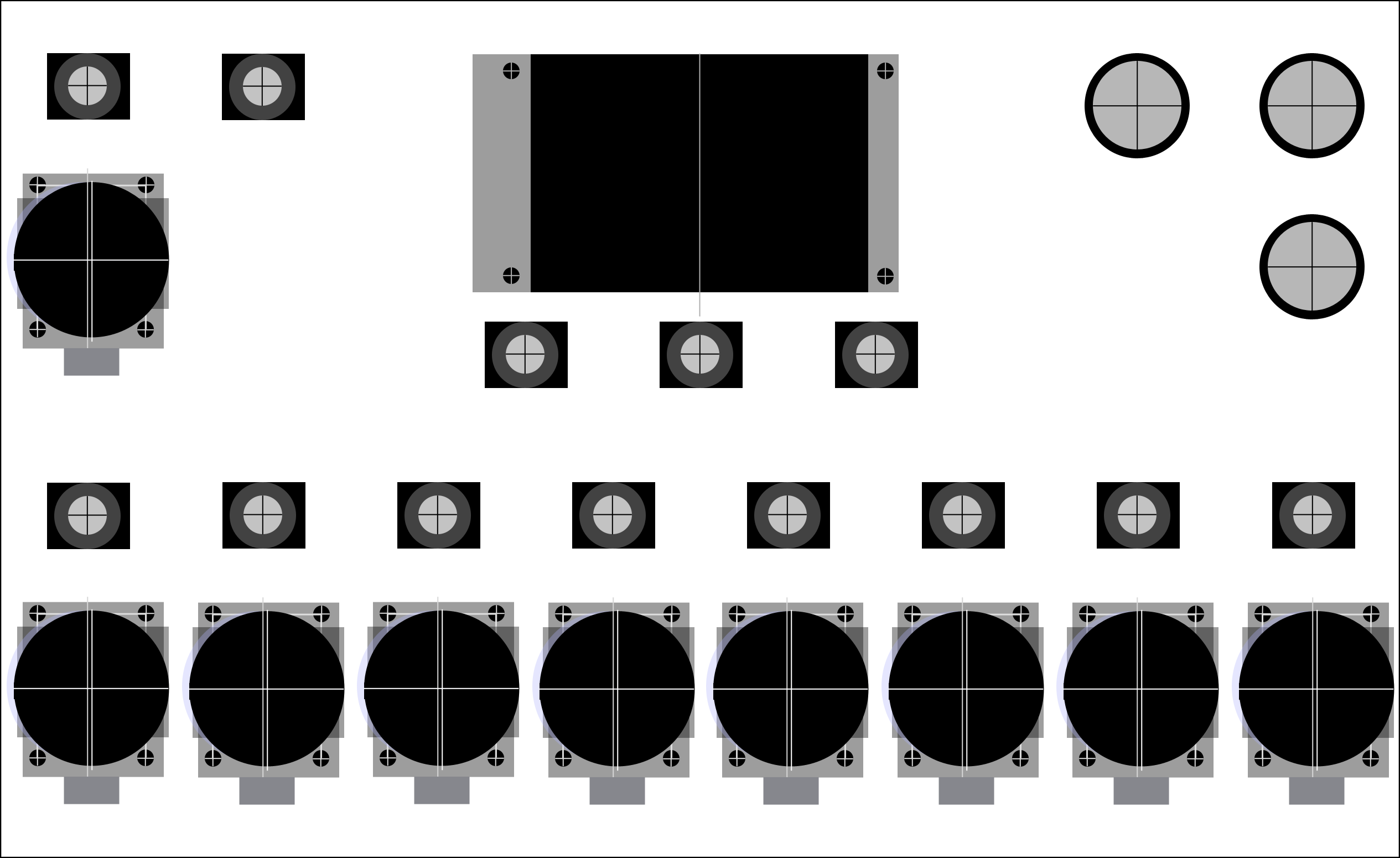
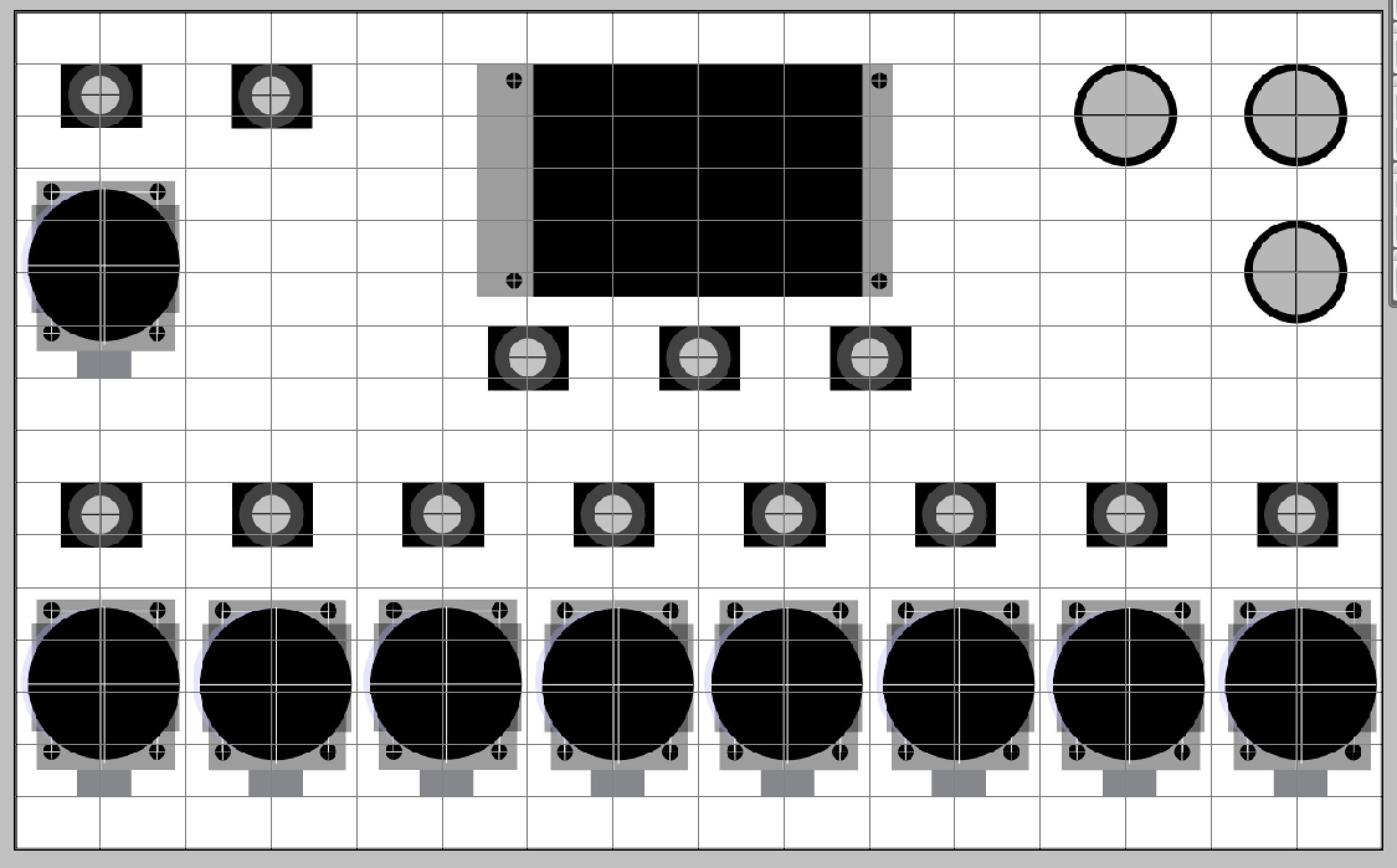
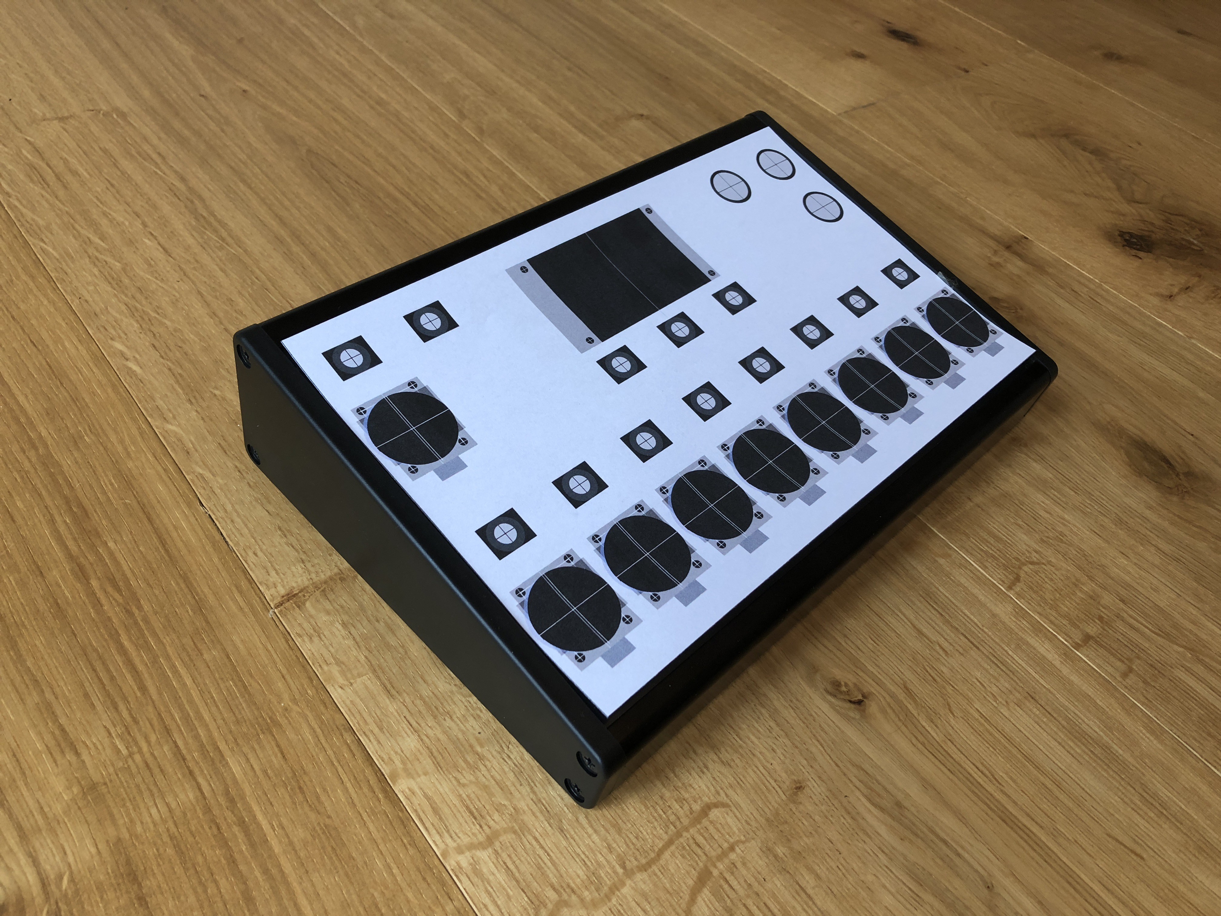
Panel Drilling Template
Unfortunately I'm not yet knowledgable in using any CAD software for producing technical drawings, so for creating a template for drilling the enclosure I used a probably-questionable alternative - Photoshop. Whilst using Photoshop probably made this process harder than it needed to be, it got the job done. Also as I'm only using this drawing as a manual drilling template, as opposed to a technical drawing for a CNC routing machine, it doesn't matter too much at the moment. See below for the final template design both with and without gridlines:
![]()
![]()
Creating the template for the joystick module was the trickiest part here, as the actual joystick isn't central on the PCB meaning the hole for the joystick is not central between the mounting screw holes.
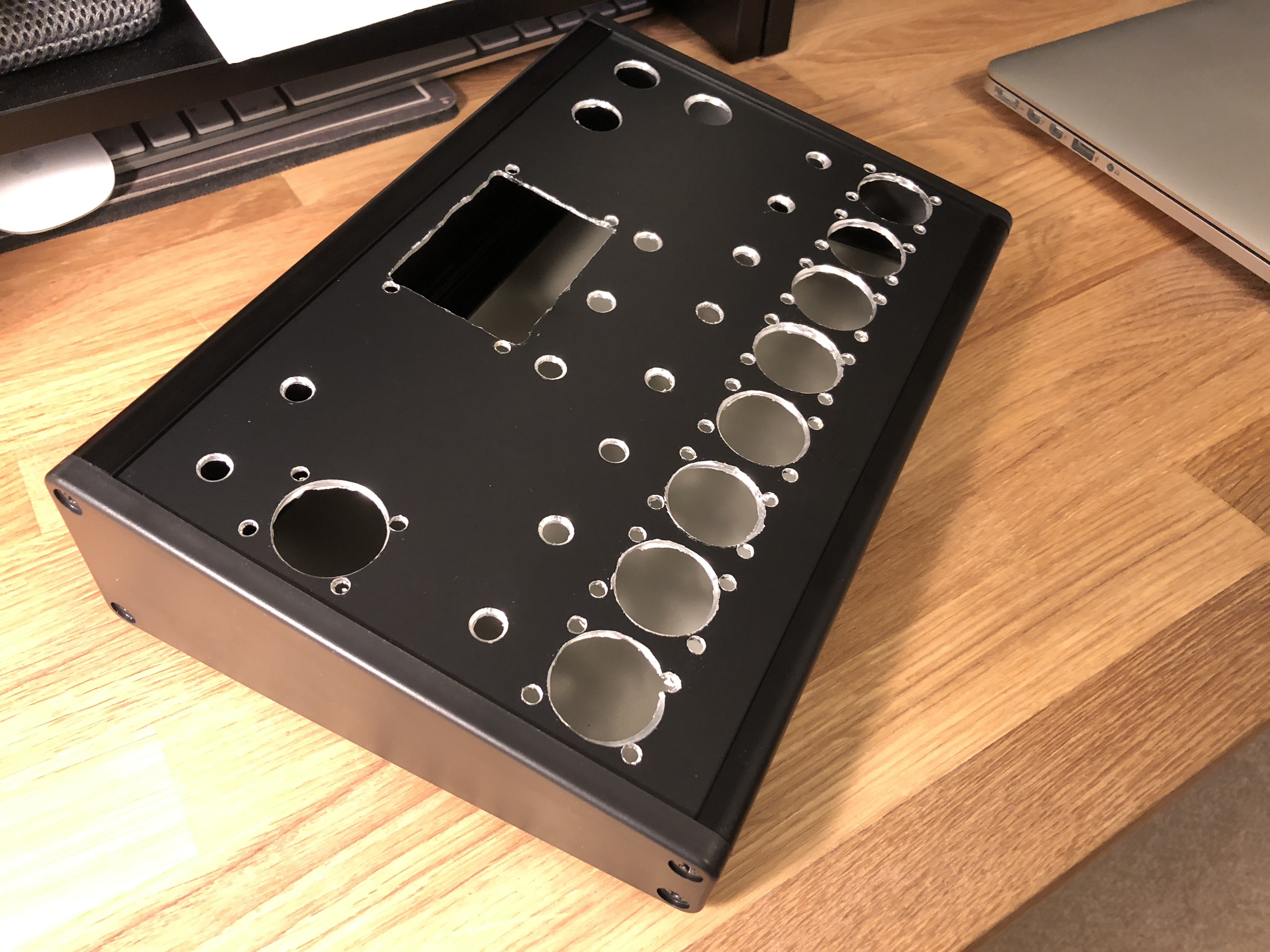
Drilling the Enclosure
To make holes to attach the controls to the enclosure I only had a drill and a Dremel at my disposal - no access to a CNC routing machine (or a CAD drawing to provide to one!).
Below are some photos of the process:
![]()
![]()
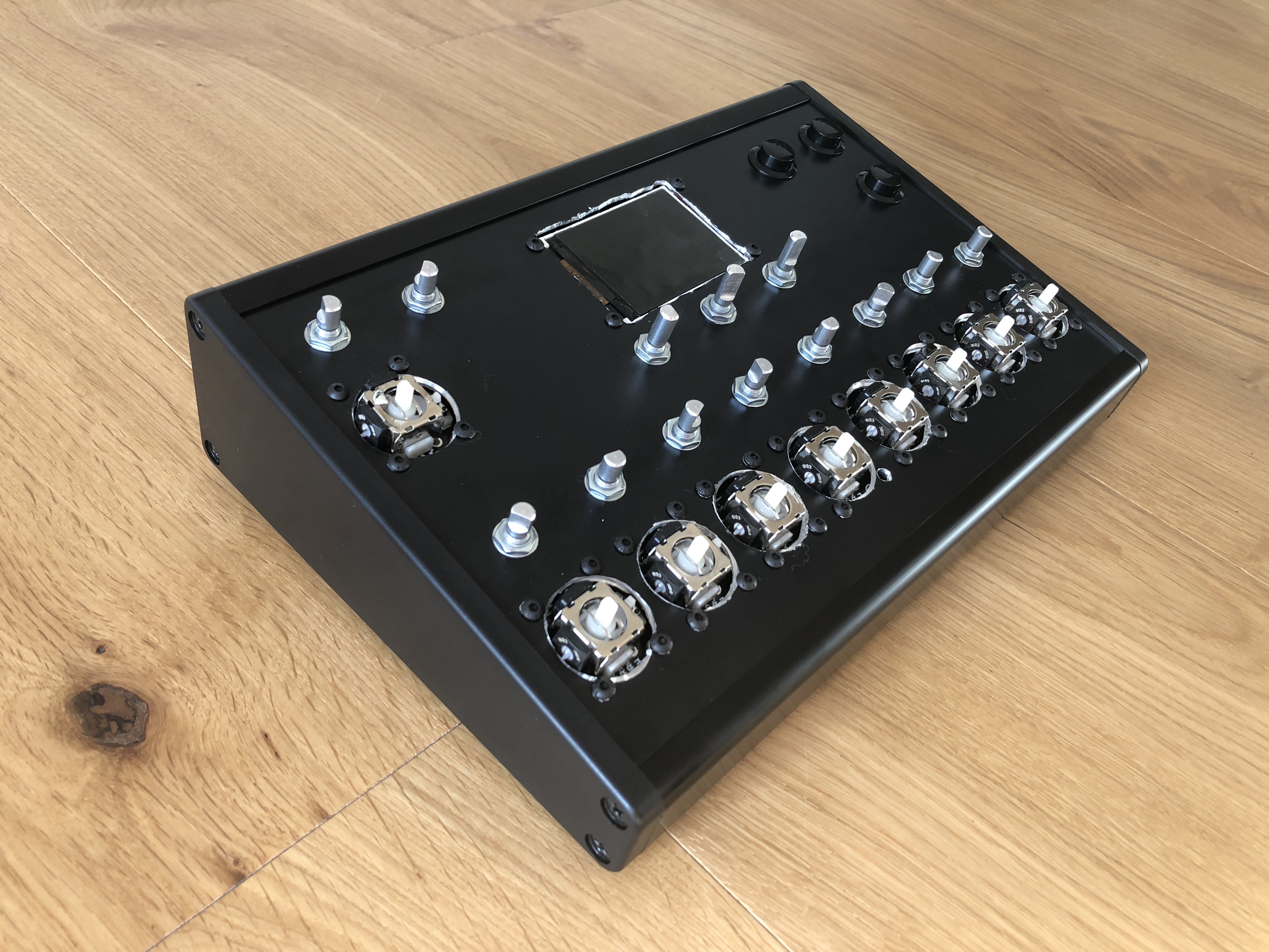
![]()
While it's not the neatest drilling job, overall I'm happy with how it came out. I'm not too happy with the messiness of the hole for the LCD (cutting out a rectangular hole with just a drill and Dremel was particularly tricky), however I'm going to attach some kind of laser cut frame to the top of the panel to tidy this up.
Hole sizes for the controls:
- Joysticks - 27mm
- Encoders - 7mm
- Buttons - 16mm
- Mounting screw holes - 4mm
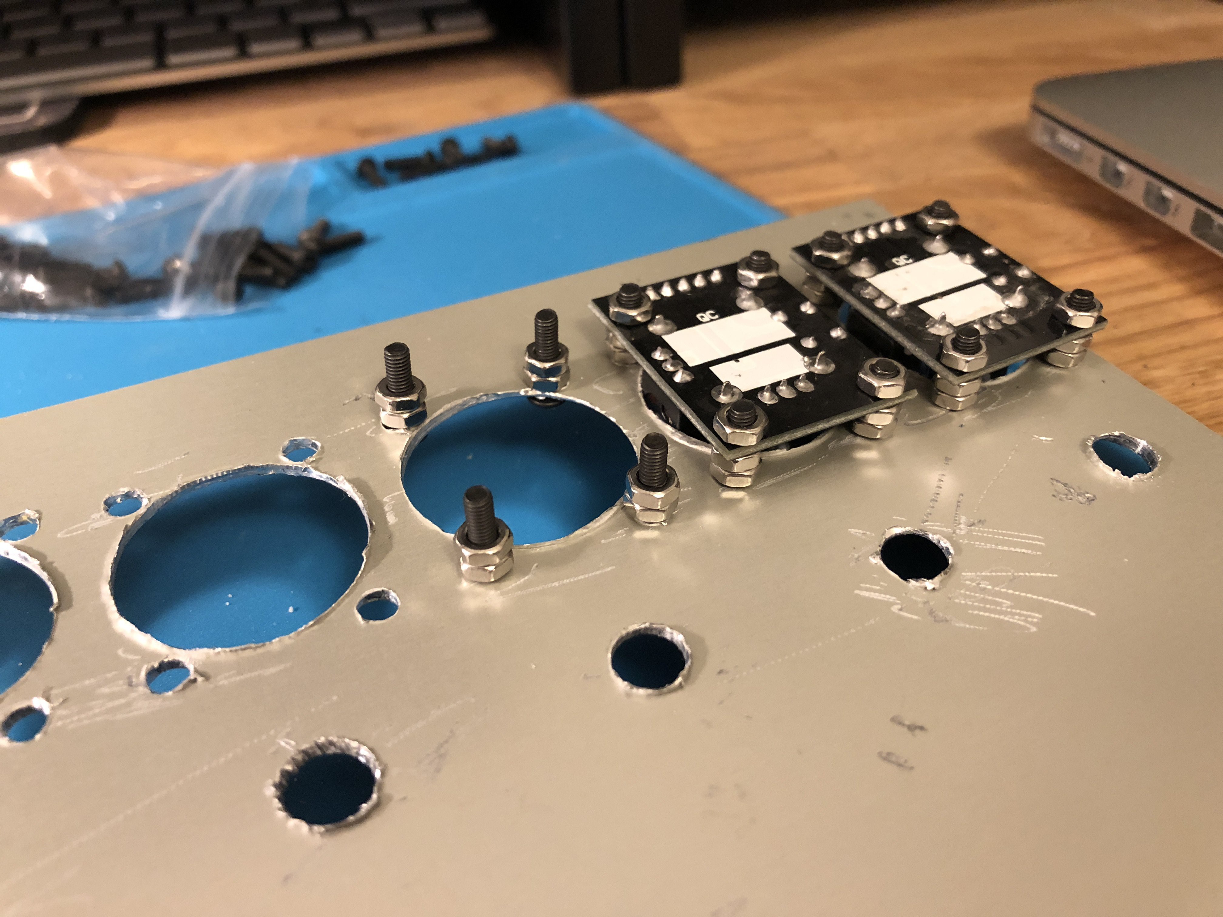
Attaching the Controls to the Panel
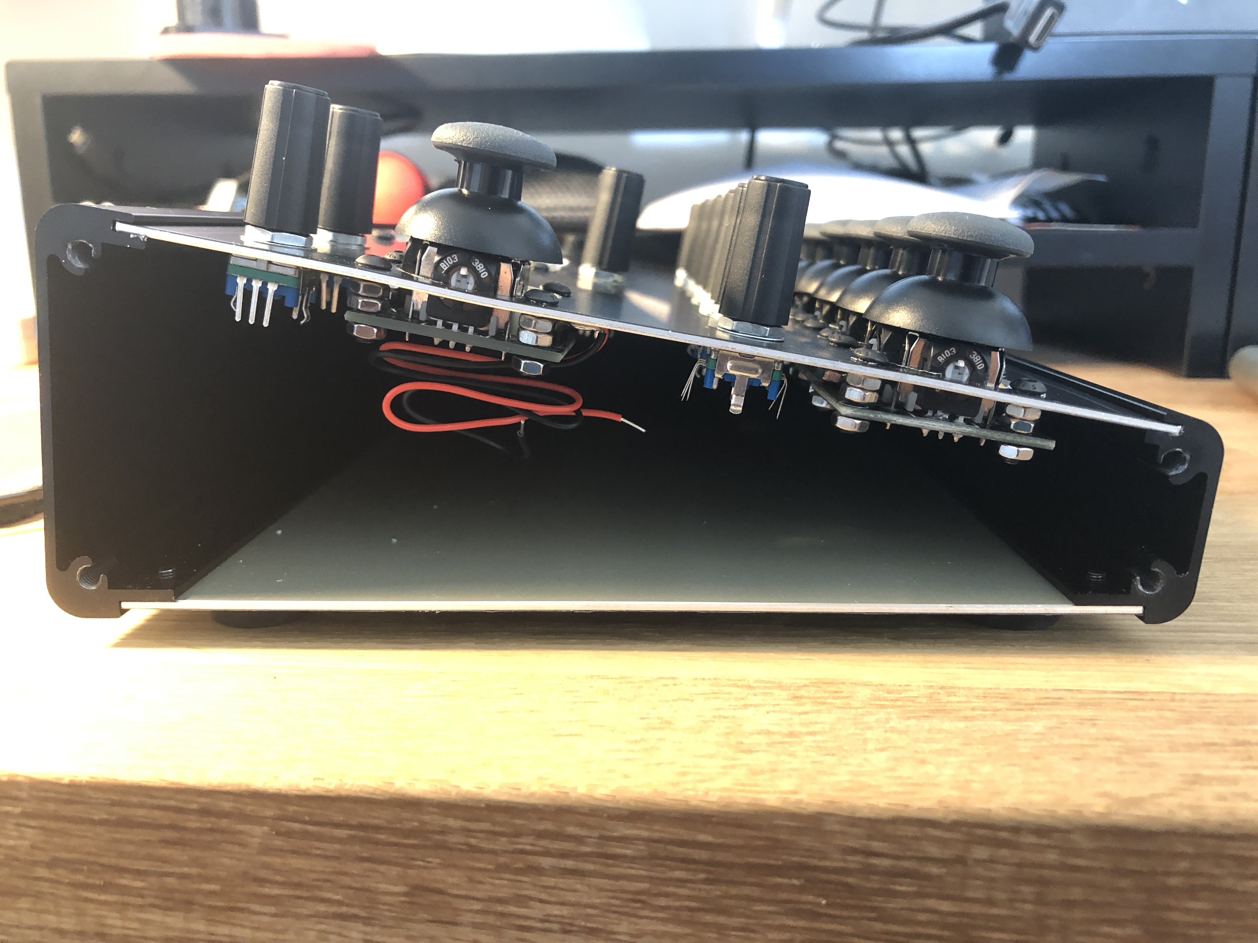
The controls are attached to the panel in the following ways:
- Joystick modules are attached via 4 x 12mm M3 screws, with two nuts on each screw used as spacers between the top of the PCB and the underside of the panel (see photo below). The spacing nuts were needed due to connectors and other parts being in the way.
- LCD module is attached via 4 x 10mm M3 screws with a single nut on each screw used as spacers, like with the joystick modules.
- Encoders are attached via nuts attached to the shaft on the topside of the panel
- Buttons are attached via nuts attached to the shaft on the underside of the panel
![]()
![]()
![]()
![]()
![]()
What's Left To Do
I've got a few things left to in regards to attaching controls to the enclosure:
- Add a laser cut frame around the LCD to tidy up the messing panel cutting
- Attach a USB socket to the rear of enclosure
- Possibly replace the knob caps to something smaller
-
Development of the LCD Menu
09/15/2018 at 09:49 • 0 commentsAfter getting started with developing test code for the ILI9341 TFT LCD I thought I'd continue along the same path and develop the LCD menu that will be used to configure the MIDI controller's settings. This implementation involved several elements - designing the menu layout, processing rotary encoder messages, creating a data structure for storing settings data, drawing to the LCD, and reading and writing to EEPROM - all of which I've described below.
First, here is a quick demo video of the LCD menu in action - using the three rotary encoders to navigate through the menu, change settings values, and showing the data being recalled after powering off the microcontroller:
(On a related note, I've now set up a GitHub repo for the project, which will include all code and design files of the project. I've made a good start on a lot of different elements of the software for the project - some of this I'll describe below, and some I'll talk about in later logs when relevant)
Designing the Menu Layout
As described in my design log of the project, the LCD menu is controlled by a set of three rotary encoders - one for selecting the settings category, one for selecting the category parameter, and one for adjusting the parameter value. Based on this, the most obvious layout choice is a three-column menu, which is the main reason why the encoders are positioned as they are.
Processing Rotary Encoders Message
To process rotary encoder messages I've created a RotaryEncoder class (see header file / source file) that uses the Teensy Encoder Library for processing encoder turns and the Teensy Bounce Library for processing the push switch messages. The classes uses callback functions to provides increment/decrement values. See the controls.h file to see how this class is used.
Data Structure for Storing Settings Data and Metadata
To store settings data as well as settings metadata (e.g. setting data min and max values), I've created a couple of structs:
- ParamData for storing data for a specific parameter
- SettingsCategoryData for storing data for a specific category
I've then created an array of SettingsCategoryData for storing all needed settings data and metadata for the device. This array will be used through the code - for setting the MIDI messages that the MIDI controls transmit, for displaying values on the LCD, and for loading and saving to EEPROM. All code relating to settings is in it's own Settings.h file.
Drawing to the LCD
I've created an Lcd.h file that includes all code for setting up and drawing to the LCD. The basic implementation of the menu is as follows:
- Text is drawn on the LCD using the LCD library's print() a println() functions, using the setCursor() function to position the text. For currently selected text, the text and background colours are reversed to highlight the text.
- All category names, parameter names and parameter values displayed on the LCD are accessed from the SettingsCategoryData array described above.
- If a new 'category' encoder message is received, it increments a 'currently selected category' value and redraws the menu's first column of text to visually update which category is selected, and then redraws the menu's second and third columns of text to show the list of parameters and their values for the new category.
- If a new 'parameter' encoder message is received, it increments a 'currently selected parameter' value and redraws the menu's second and third columns of text to visually update which parameter and value is selected.
- If a new 'value' encoder message is received, it increments the value of the currently selected parameter and redraws the value in the third column of text to visually update the parameter value.
See the Lcd.h file for the implementation of this.
Reading and Writing to EEPROM
In order for the settings to be recalled after the device has been powered off, the settings values need to be stored in the Teensy board's built-in EEPROM memory using the Arduino EEPROM library.
Each parameter value of each category is stored in it's own memory address (which stores a single byte). The memory address structure is grouped and ordered by category, with space for up to 16 parameters for each of the 13 categories. For example, addresses 0-15 and for the parameters of category 1, 16-31 for category 2, 32-47 for category 3, and so on.
All data is read from EEPROM when the Teensy is booted, being put directly into the SettingsCategoryData array.
As EEPROM has a limited write endurance (on Teensy this is 100,000 cycles) I've implemented writing to EEPROM to only happen periodically and only for parameter values that have changed (using a member of the ParamData struct to flag when a value has changed).
See the Settings.h file for the implementation of this.
-
Testing the ILI9341 TFT LCD with Teensy
09/10/2018 at 08:41 • 5 commentsI'm still waiting for the last few components to arrive before I can build the controller, however one thing I wanted to do first is test my chosen LCD with the Teensy microcontroller. I've never used a TFT LCD with Arduino or Teensy before, so I first wanted to make sure that I could get the desired functionality and performance out of the LCD.
The LCD I am using is a 2.4" 320x240 TFT LCD with a ILI9341 controller chip which appears to be based off of an Adafruit design, which can be used with a Teensy-optimised Adafruit_ILI9341 library for better performance.
Connections
To connect the LCD to the Teensy 3.6 board I followed the connections guide on the Teensy website:
ILI9341 Pin Teensy 3.x / LC Pin Notes VCC VIN Power: 3.6 to 5.5 volts GND GND CS 10 Alternate Pins: 9, 15, 20, 21 RESET +3.3V D/C 9 Alternate Pins: 10, 15, 20, 21 SDI (MOSI) 11 (DOUT) SCK 13 (SCK) LED VIN Use 100 ohm resistor SDO (MISO) 12 (DIN) Arduino Library
I decided to use the Teensy-optimised Adafruit_ILI9341 library over the standard Adafruit_ILI9341 library due to the demonstrated increased frame rate and performance of the former. I downloaded the library from the Github page and followed the provided instructions to install it into the Arduino software.
Using the library
After a quick online search I couldn't find any decent tutorials on using the LCD's Arduino library to draw shapes (which is mostly what I want the LCD to do), however after dissecting the example sketches that come with the library it became quite clear how to do it. The best source to find out what functionality is provided is the library's main header file, which shows all the functions that library provides such as drawRect, fillRect, fillCircle, and many more.
Test/Example Code
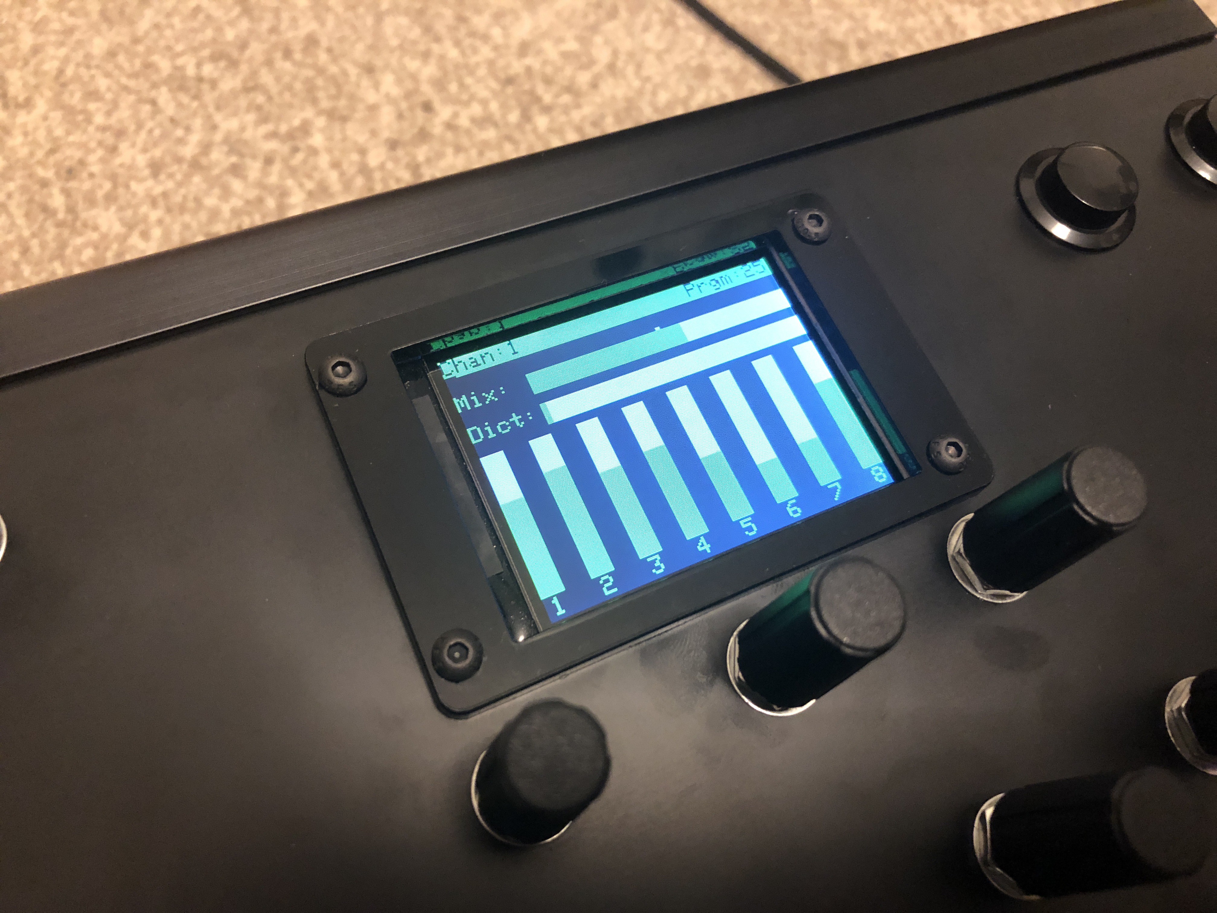
To test the LCD and Arduino library I decided to attempt to create a simple Teensy sketch that draws eight sliders on the LCD that each change their value from a MIDI CC message received over USB-MIDI - something that the final controller software will need to do.
Below is the code I created to do this. See the comments in the code to see how it works. The exact MIDI CC numbers I am using in this test code match the default CCs that the KORG nanoKONTROL MIDI controller sends from it's sliders (see the below example video). If you would like to upload this to a Teensy yourself, you'll need to set the 'USB Type' to 'MIDI' in the tools menu.
#include "ILI9341_t3.h"

// TFT pins
const uint8_t TFT_DC = 9;
const uint8_t TFT_CS = 10;

// Use hardware SPI (#13, #12, #11) and the above for CS/DC
ILI9341_t3 tft = ILI9341_t3 (TFT_CS, TFT_DC);

const int LCD_FRAME_RATE = 30;
long previousMillis = 0;

const int BCKGND_COLOUR = ILI9341_BLACK;
const int SLIDER_COLOUR = ILI9341_RED;
const int SLIDER_BCKGND_COLOUR = ILI9341_DARKGREY;

const int SLIDER_WIDTH = 20;
const int SLIDER_MAX_SIZE = 127;
const int SLIDER_SPACING = 40;

const uint8_t NUM_OF_SLIDERS = 8;
const uint8_t SLIDER_CC_NUMS[NUM_OF_SLIDERS] =  {2, 3, 4, 5, 6, 8, 9, 12};

int sliderValue[NUM_OF_SLIDERS] = {0};
int prevSliderValue[NUM_OF_SLIDERS] = {0};

uint8_t midiCcValue[NUM_OF_SLIDERS] = {0};
uint8_t prevMidiCcValue[NUM_OF_SLIDERS] = {0};

void setup()
{
  tft.begin();
  tft.setRotation (3);
  tft.fillScreen (BCKGND_COLOUR);

  //draw a vertical rectangle 'slider' at the bottom of the screen
  for (uint8_t i = 0; i < NUM_OF_SLIDERS; i++)
    tft.fillRect (i * SLIDER_SPACING, tft.height() - SLIDER_MAX_SIZE, SLIDER_WIDTH, SLIDER_MAX_SIZE, SLIDER_BCKGND_COLOUR);

  usbMIDI.setHandleControlChange(ProcessMidiControlChange);

}

void loop()
{
  //Read from USB MIDI-in
  usbMIDI.read();

  //update the LCD display at the set frame rate
  if ((millis() - previousMillis) > (1000.0 / (float)LCD_FRAME_RATE))
  {
    updateDisplay();
    previousMillis = millis();
  }
}

void ProcessMidiControlChange (byte channel, byte control, byte value)
{
  for (uint8_t i = 0; i < NUM_OF_SLIDERS; i++)
  {
    if (control == SLIDER_CC_NUMS[i])
    {
      midiCcValue[i] = value;

      if (midiCcValue[i] != prevMidiCcValue[i])
      {
        //set the new value for the slider
        sliderValue[i] = midiCcValue[i];

        prevMidiCcValue[i] = midiCcValue[i];

      } //if (midiCcValue[i] != prevMidiCcValue[i])

    } //if (control == SLIDER_CC_NUMS[i])

  } //for (uint8_t i = 0; i < NUM_OF_SLIDERS; i++)

}

void updateDisplay()
{
  for (uint8_t i = 0; i < NUM_OF_SLIDERS; i++)
  {
    //if the slider value needs updating
    if (sliderValue[i] != prevSliderValue[i])
    {
      if (sliderValue[i] > prevSliderValue[i])
      {
        //increase the size of the slider by drawing the value difference on the top
        tft.fillRect (i * SLIDER_SPACING, tft.height() - sliderValue[i], SLIDER_WIDTH, sliderValue[i] - prevSliderValue[i], SLIDER_COLOUR);
      }
      else
      {
        //decrease the size of the slider by 'clearing' the value difference from the top
        tft.fillRect (i * SLIDER_SPACING, tft.height() - prevSliderValue[i], SLIDER_WIDTH, prevSliderValue[i] - sliderValue[i], SLIDER_BCKGND_COLOUR);
      }

      prevSliderValue[i] = sliderValue[i];

    } //if (sliderValue[i] != prevSliderValue[i])

  } //for (uint8_t i = 0; i < NUM_OF_SLIDERS; i++)

}
Example Video
Below is an example video of the above code running on a Teensy 3.6, using a KORG nanoKONTROL USB-MIDI controller as the MIDI input device, with MIDI messages being routed from the nanoKONTROL to the Teensy using my MacBook running the MIDI Patchbay software.
Based off of the performance of this test code, I am confident that this LCD will be perfect for this project.
Turnado Hardware MIDI Controller
The development of a dedicated hardware MIDI controller for the Turnado audio FX software plugin.