Close
0%
0%

Boson Frame Grabber

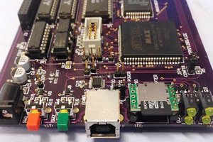
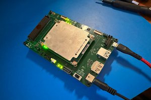
Simple FPGA based PCB to capture thermal images from a FLIR Boson camera on to a microSD.

Similar projects worth following
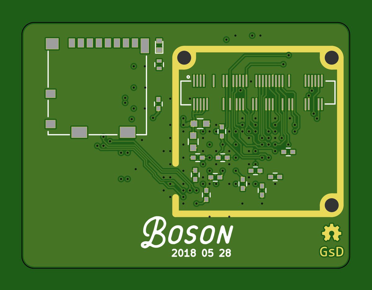
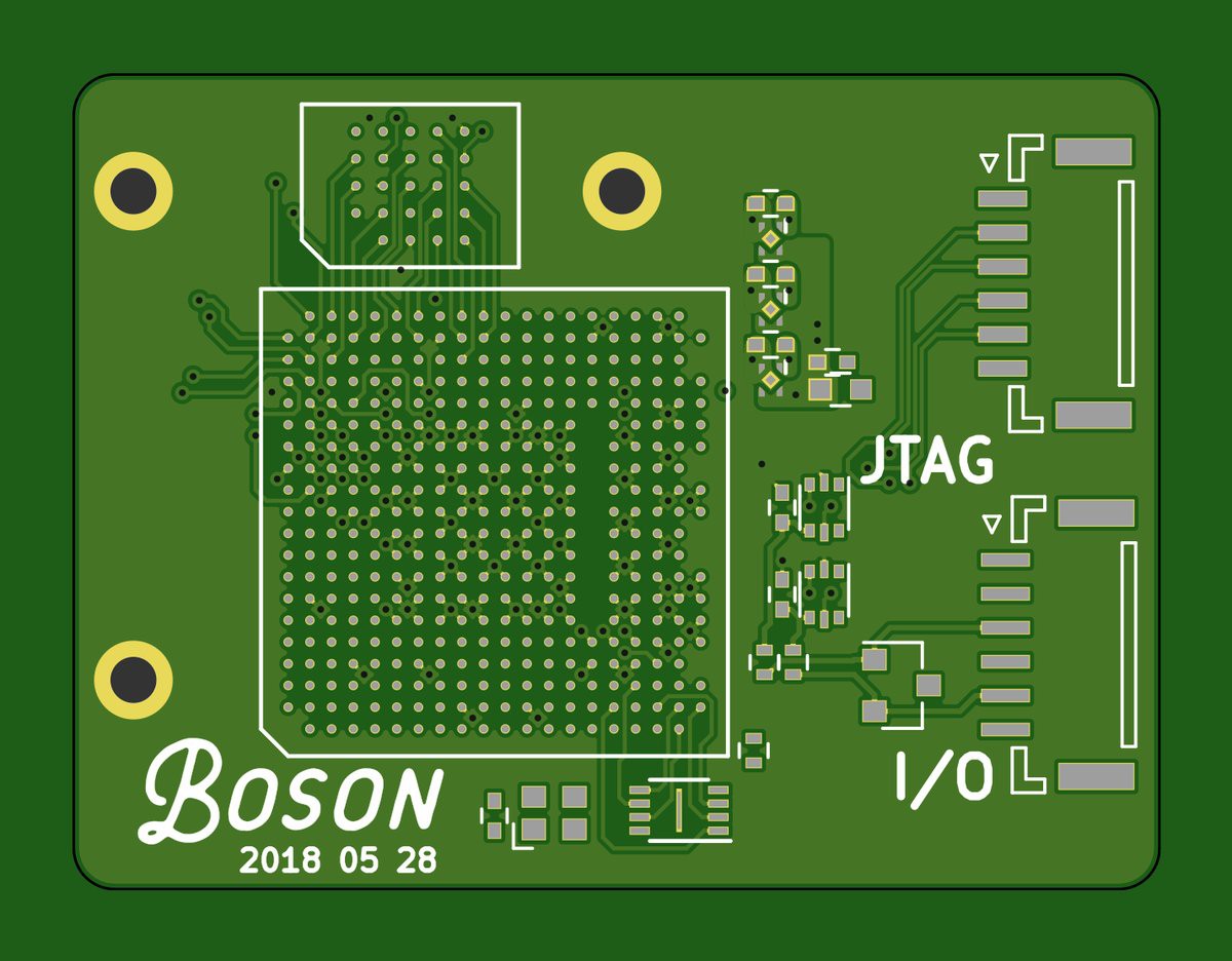
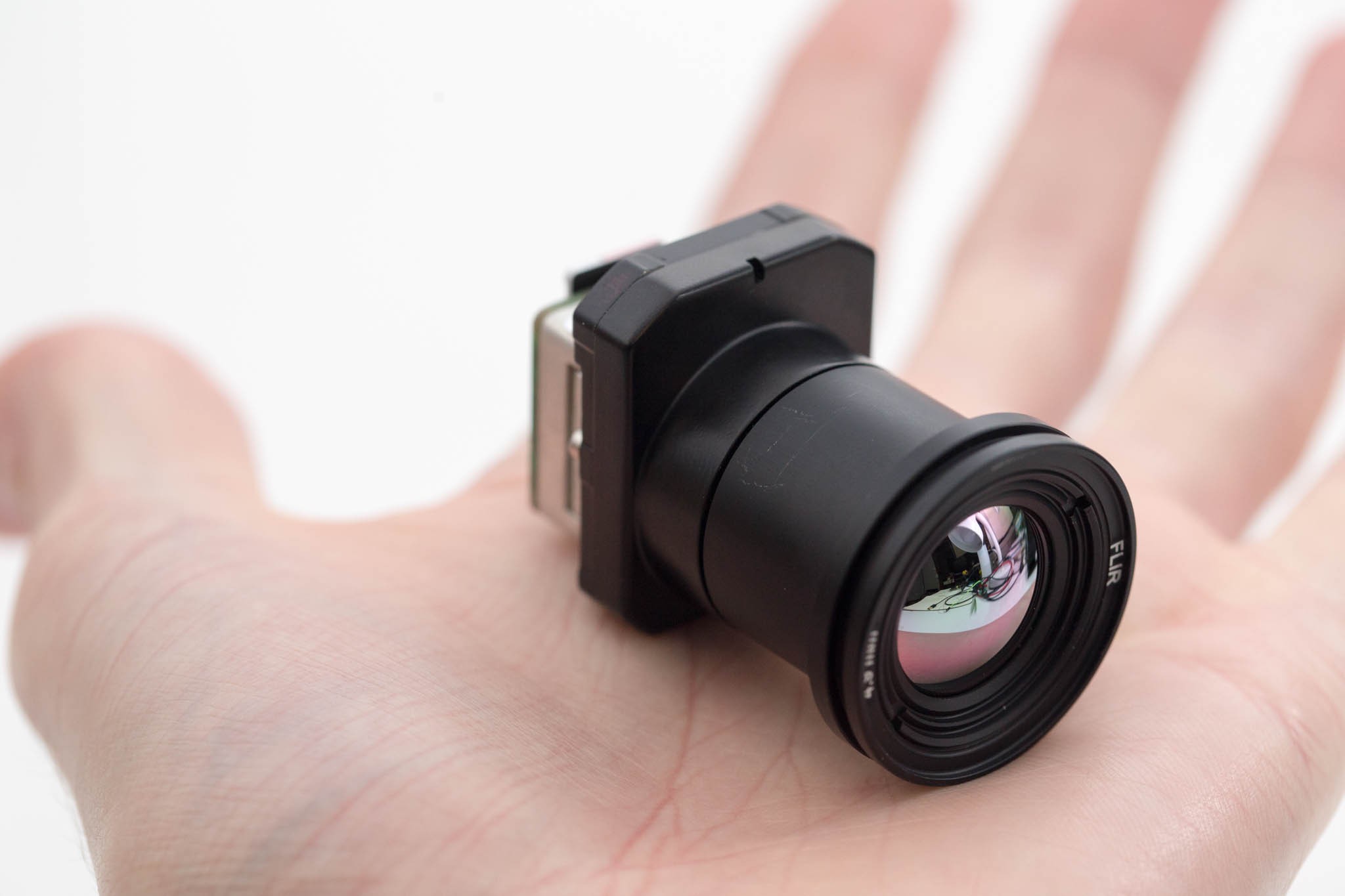
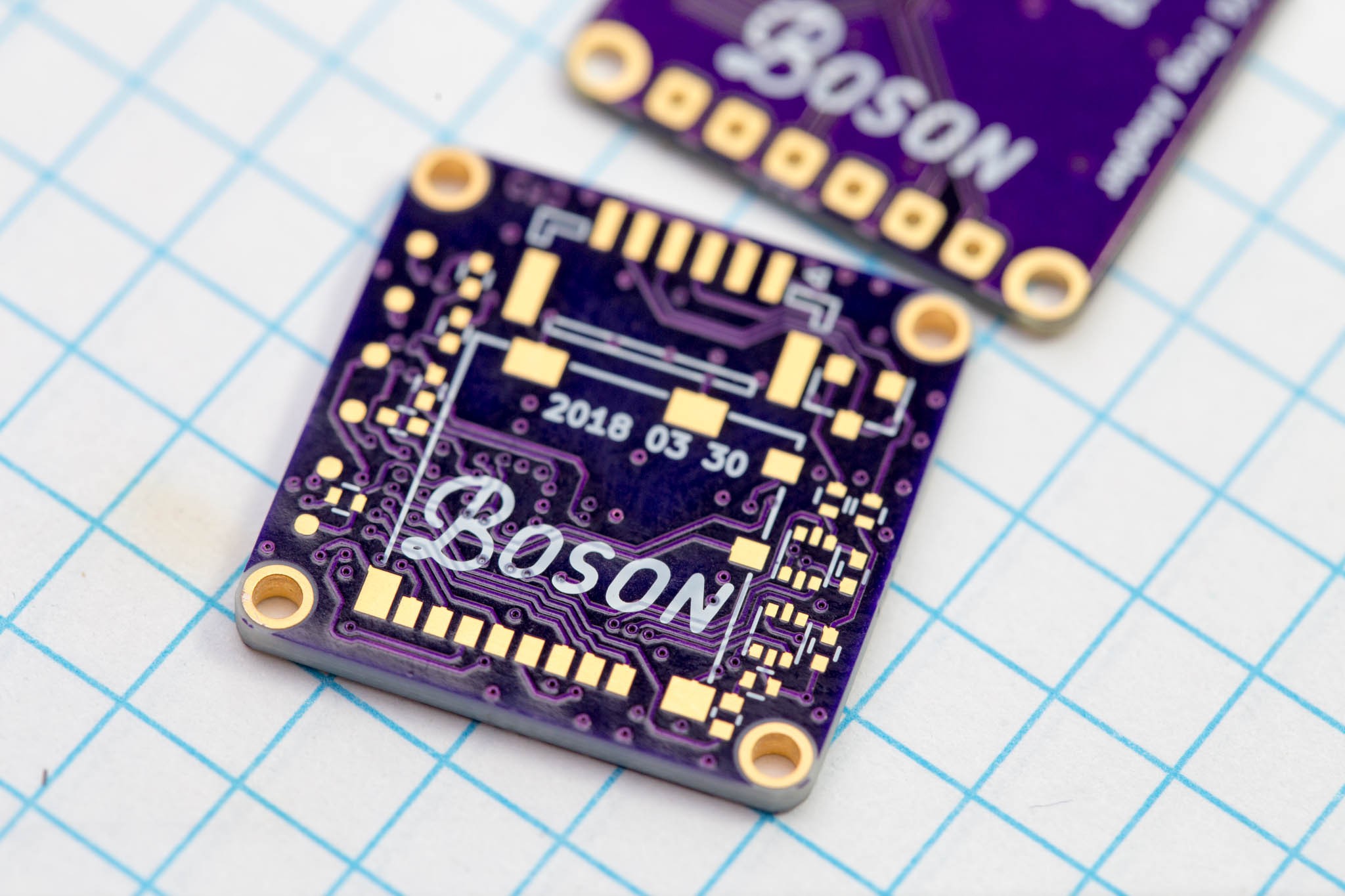
A small PCB designed to attach to the backside of the FLIR Boson Thermal Camera.
The PCB facilitates configuration of the camera along with capturing data to an SD card.

This project is mostly an exercise in project-based learning. Instead of researching and reading about FPGAs, I want to create a project actually using them. Of course, this means that I'll likely get things wrong, but that's just part of the learning experience.

A huge shoutout to Group Gets, without their support this project would not have made it this far! They are a FLIR Boson Distributor, check out their range here: https://store.groupgets.com/collections/flir-boson-accessories

This project is a miniature FPGA based PCB to capture and save images from a camera stream. The FPGA used in the lattice ECP5, the board has 64Mbit of RAM and 8Mbit of FLASH. It runs a RISCV CPU internally to handle the processor centric tasks (UART, state machine, FatFS), but has dedicated hardware to handle the video stream and communicate to the SD card using 4bit SD protocol.

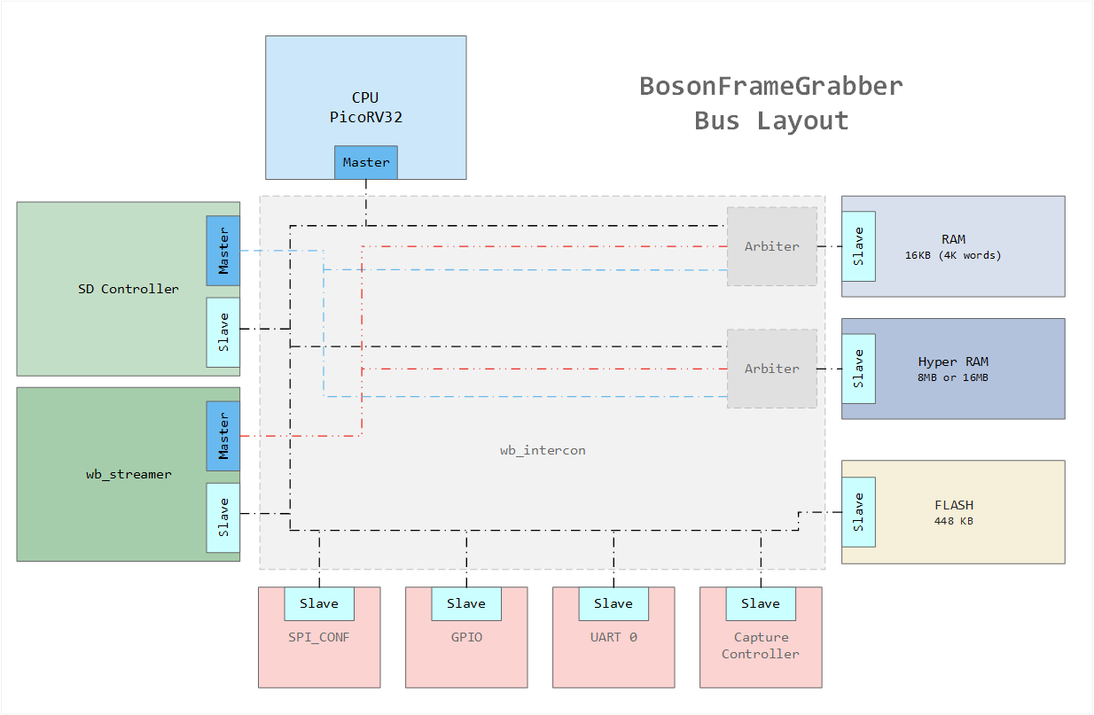
The modules inside the FPGA follow the following bus diagram. They all make use of a common wishbone buses.
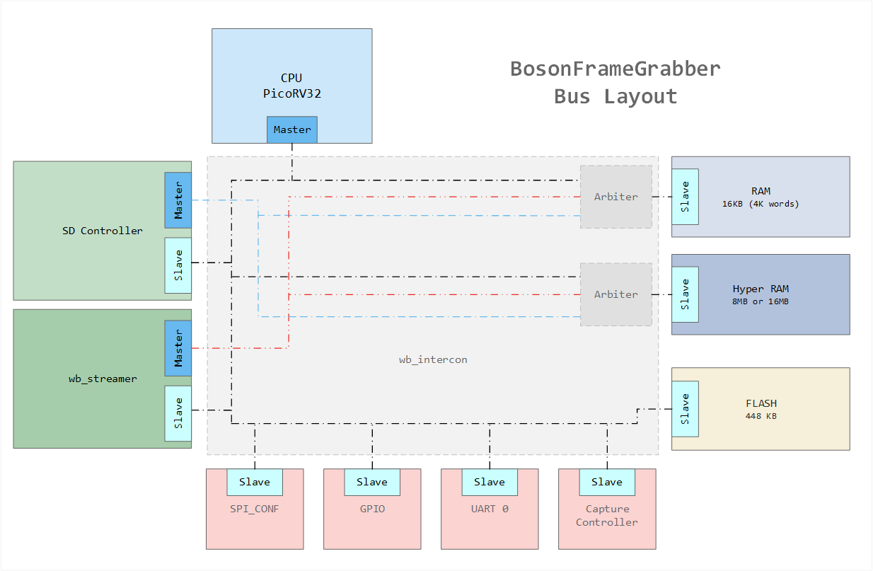
All bus connections are created by this project: https://github.com/olofk/wb_intercon. wb_intercon automates the creation of muxes and arbiters required to connect various wishbone components including multiple masters.

bosonFrameGrabber_sch.pdf

Schematic. (PDF)

Adobe Portable Document Format - 241.95 kB - 10/02/2018 at 00:20

Preview

bosonFrameGrabber_1_02_bom.csv

Bill of Material. (DigiKey P/Ns)

ms-excel - 1.78 kB - 09/10/2018 at 06:56

Download

bosonFrameGrabber_20180528_192938.zip

Gerber files

x-zip-compressed - 171.77 kB - 09/10/2018 at 06:43

Download

  • 1 × LFE5UM-25F-6MG285C Lattice ECP5 FPGA 25k LUT
  • 1 × S27KS0641DPBHI020 64Mbit PSRAM HyperRAM 1.8V
  • 1 × BM06B-GHS-TBT(LF)(SN)(N) 6 pin JST GH series, Top entry.
  • 1 × DF40HC(4.0)-80DS-0.4V(51) Hirose DF40 80pin Connector
  • 14 × CL05B104KP5NNNC 100nF 0402 Capacitor

View all 18 components

  • Boson 640 working.

    greg davill10/01/2018 at 06:46 2 comments

    After working on updating the verilog module used in my camera to support the HyperRAM using DDR modules and the PLL of the ECP5 FPGA I'm using.

    The change increased the performance by 4x. This enables us to capture the datarate from the Boson 640 cores.

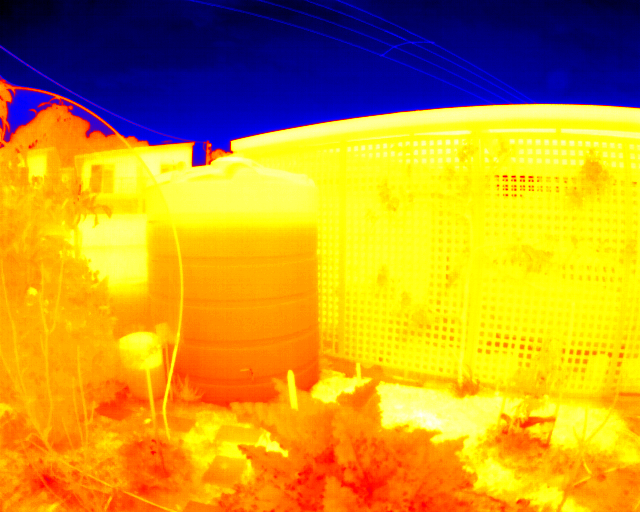
    Here is a photo of the water tank ~80% full.

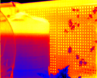
    For reference here is the same tank using the Boson 320 core.

    There are still many performance improvements I have on a list to work on.

    But the major functionality of the device is working. We can capture Images at about 3 FPS.


    Here is the layout of the internal modules in the FPGA

    All the components make use of a common wishbone bus. There are 3 masters that enable data-flow through the device without requiring the CPU. Basically these are simple DMA controllers.

    Everything is wired together using wb_intercon (https://github.com/olofk/wb_intercon). This package automatically creates a verilog file with muxes/arbiters/address decoders based on a simple config file.

    I'm using picoRV32, as this worked very well on the HX8K hardware I started with. I studied RISCV in a computer architecture class, so I have a good base of knowledge when debugging issues. The CPU handles the filesystem using FatFS. This enables us to access FAT, and exFAT formatted SD cards.

    The firmware is still very basic. It's operation is as follows
    • Prime wb_streamer to capture the camera stream into HyperRAM.
    • Wait for vsync signal from the camera.
    • Capture 1 frames worth of data.
    • The RISCV handles creating and allocating a new file. (IMG_0001.RAW)
    • The DMA of the SD controller writes the file contents from HyperRAM into the SD card.
    • We Finally blinks a LED and repeat.

    To the user once powered all they see is the LED on the back of the camera blinking away.

  • SD optimisations

    greg davill10/01/2018 at 06:29 0 comments

    When working with low level SD drivers, there are few things you need to do in order to get anywhere near the actual write speeds advertised on cards.

    MULTIPLE_BLOCK_WRITE (CMD25) is probably the most important things you can do. This needs to be combined with SET_BLOCKLEN (CMD23) in order to tell the internal logic in the SD card about our intention to write more than 1 block.

    Here is an example of writing a 512kb file to an SD card. (1 bit mode, 12MHz clock, exFAT FS)


    About 2.5s, this results in a write speed ~204kBytes/s. When running in 1bit at 12MHz our bus speed is ~1500kBytes/s. Even with overhead of filesystems we should be able to do better.

    Lets switch to using CMD23 and CM25.

    For clarity the scale remains to same. This time it took 0.45s, which results in ~1100kByte/s write speed. MUCH better!

    You will notice that the CMD line is active during the transaction, this indicates a start/stop of dataflow. Why? This is due to the structure of the file system. By default FatFs will only write continuous streams until you hit a cluster boundary. In this case this card was formatted with a 32kb clusters. this results in 16 separate transactions.

    Every one of these transactions incurs a 1ms write time when the card is busy, and can't be used. FatFs includes a command that lets you pre-allocate continuous space for a file. f_expand. If we use f_expand then we can perform all our filesystem tasks in one go. then have a free-run to write the file out.

    Total time 0.42 = 1200kBytes/s

    We are still operating in 1bit mode, 12MHz. All we have done is alter the firmware. I'm using high quality Samsung cards that have a stated max write speed of 60MB/s. You can see that we don't incur any delays while writing all the main data for the file.

    In order to reach a 60MB/s write speed you require hardware that can switch the signalling to the SD card into UHS mode. This uses 1.8V signaling, instead of the standard 3.3V.

    As my hardware does not contain this additional hardware, so I'm limited to using HS mode. 50MHz 4bit which should enable near to 25MByte/s.

  • First Image captured!

    greg davill09/27/2018 at 00:45 0 comments

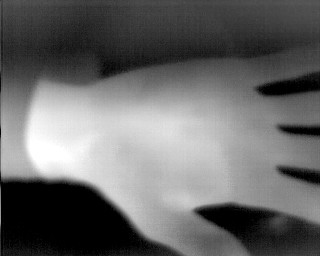
    After spending a few weeks tracking down a bug caused by a bad reset circuit and incorrect PLL usage. I've finally captured an image using the new hardware!

    It appears that I've lost the first pixel in the frame somewhere into the ether. This results in the single pixel band down the left side of the image.

    Still some more work to do in terms of performance. Almost every part of the design can be improved in same way to improve the speed at which I can record these images from the camera module to the SD card.

    • SD multiblock write
    • SD 4bit mode
    • Burst read from HyperRAM -> SD controller
    • Use PLL for HyperRAM (4x speed increase)
    • Set HyperRAM latency to lowest speed + variable latency (~2x speed increase)
    • FatFS f_expand() + single low-level multblock write

    The next stage in the project is working on the SD low level drivers to support CMD25 (Multiple block write). When combined with CMD23/ACMD23 (Number of blocks to erase) we can really boost the write speed of the SD card. At this time the image is written in 512 byte blocks to the card, the card accepts this block and performs an erase/write on its internal FLASH. I'm using high quality Samsung  cards, and I see this process takes ~1ms

    You can see the start of the image being written to the card. The first reads/writes are dealing with the exFAT filesystem, the regular pattern on the right side is the image data written in 512byte blocks, and subsequent busy cycle from the card. The SD card indicates it is busy by holding the DAT line LOW.

    You can see that our data cycle and busy cycle are pretty even right now. Data cycle takes ~0.7ms, busy: ~1ms. If we enable 4bit mode now we can decrease the data cycle by 4, but the busy cycle remains unchanged. This results in very little overall speed improvement.

  • Not another PCB.

    greg davill09/09/2018 at 07:09 0 comments

    The thought of shelving this project for 8 weeks waiting for the FPGA left me discouraged. What if after 8 weeks I assemble the board and it doesn't work?

    I decided to create a new PCB, this time using an ECP5 in a larger 381 ball (17x17) package.

    Read more »

  • Performance, a new camera, another revision?

    greg davill09/09/2018 at 06:36 0 comments

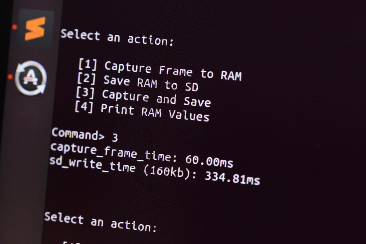
    With v1_01 working. I now had a better understanding of working with verilog, and a much better understanding of LUT utilization and timing closure. I'd managed to fit in a hardware SPI module, with DMA. with these improvement and the system running at 24MHz (max frequency of my design typically sat around 30MHz for the iCE40HX) the 160Kb images from the camera took around 300ms to capture. Not bad!

    But the iCE40HX8K, while a great little chip is too small and under powered to really push this project to the next level. I had designed the PCB to accommodate a 4bit SD interface, I had wired CMD,DAT0-3,CLK to the FPGA. Using SPI mode was easy to validate that the hardware was working. But for a notable performance increase I'd need to switch to a real SD controller. The controller I wanted to work with (https://github.com/mczerski/SD-card-controller) did not fit in the remaining space of the iCE40HX8K.

    Around this time I was contacted by GroupGets. a distributor of the FLIR Boson. They were very impressed with the work I was sharing on twitter, and donated a Boson 640 for me to test with and ensure everything worked.

    This Boson 640 is a beast! 640x512 pixel resolution, 60Hz update rate, and this has the widest angle lens: 95 degree FOV.

    Unfortunately the added pixels (4x an many!) and the added frame rate means this camera uses a 27MHz pixel clock. This did not play well with my 24MHz capture hardware. I needed to rebuild it. Better, faster....(stronger?)

    Read more »

  • Prototypes 1,2,3...

    greg davill09/09/2018 at 04:29 0 comments

    I had mentioned in the last log that I created the footprint wrong for the HyperRAM device. Well my first bosonFrameGrabber PCB had the same errata.

    Read more »

  • Project Goals and Motivation and Background

    greg davill09/09/2018 at 03:44 1 comment

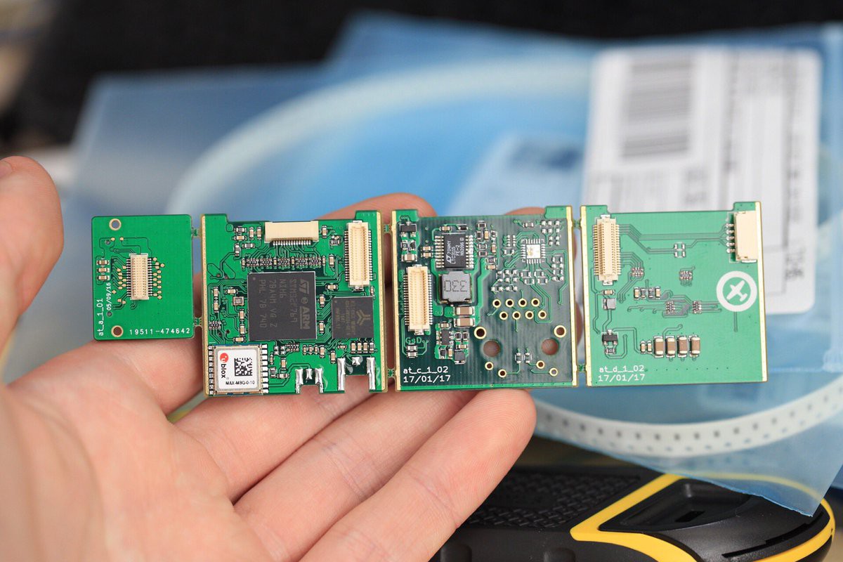
    At my day job a few years ago I designed a reasonable small product that attaches to the back of a FLIR Tau2 thermal camera core. The product takes the digital video stream from the camera and saves this information to an SD card, it also included an ethernet 100MB/s interface. Since the Tau2 is a small camera, so the electronics in this product is made up of a "stack" of boards.


    The Tau2 outputs a 14bit video stream of it's 640x512 pixel array. This stream needs to handle upto 60Hz on some product variants, so it features a 27MHz pixel clock. In order to ensure a frame from the camera was successfully captured I designed in enough memory to fully buffer a frame (> 640kb). It's design was based around an ARM M7 microcontroller. Utilizing external DDR memory and it's included 14bit Digital Camera Module Interface (DCMI).

    At the time I knew this was the perfect application for an FPGA, but having no hands on experience with them I decided it was too risky at the time.

    Read more »

View all 7 project logs

Enjoy this project?

Share

Discussions

Vitalii S. wrote 08/13/2020 at 19:56 point

that's really cool!
lots of questions..

1. what's the power consumption;
2. do you plan to add a display to output the realtime image?

  Are you sure? yes | no

agate17 wrote 07/18/2019 at 00:08 point

I did similar project. It run into limitation of SD write speed. So I end up using low power ARM A7 with DDR in one package.    Video is going  to parallel CSI. It solves almost all issue. uSD write speed is 22MB/s and for uncompressed 640x480 30Hz we need only 18.5MB/s.  The bonuses are streaming to Ethernet , sound recording and reuse of all wonderful things made for Linux.

  Are you sure? yes | no

kozuch wrote 10/12/2018 at 22:59 point

Marvelous project! I am completely new to Boson, but is FPGA really necessary? Would a microcontroller (STM32 etc.) not do the job? STM32duino (STM32F4) is capable of handling parallel image sensor interface... Would be much simpler than FPGA probably?

  Are you sure? yes | no

Jan wrote 10/01/2018 at 13:37 point

Amazing build! Always fascinated by stuff like this, especially FPGAs. But after all I'm just a mechanical engineer, not a embedded hardware engineer like you. You know your stuff :)

  Are you sure? yes | no

greg davill wrote 10/02/2018 at 00:26 point

Thanks for the kind words!

  Are you sure? yes | no

tfischer wrote 09/17/2018 at 11:43 point

How did you solder the bga: oven, reflow station, etc...?

  Are you sure? yes | no

greg davill wrote 09/19/2018 at 00:56 point

The top-side (BGAs) was done with a desktop reflow oven. It's too difficult for the paste I own to apply through a stencil onto a 0.2mm BGA pad, so I applied only flux underneath the main BGA. For the bottom side (0402 passives, SD, connectors) I hand soldered.

  Are you sure? yes | no

RUN.CAM wrote 09/11/2018 at 04:58 point

Hi, great job! What is the file format saved on SD card?  Any file system implement in your FPGA?

  Are you sure? yes | no

greg davill wrote 09/11/2018 at 05:18 point

Thanks! I am still working on the firmware. The FPGA contains a softcore RISCV processor that can currently handle FAT32/exFAT filesystems. The images are stored as RAW or TIFF.

  Are you sure? yes | no

Similar Projects

Does this project spark your interest?

Become a member to follow this project and never miss any updates