 bornach

I wanted to explore using addressable LEDs to visualize orientation data, however the NeoPixel rings one can buy from Adafruit or from Ebay sellers tend to max out at 60 LEDs. I'd have to sacrifice resolution if the LEDs could not somehow be made to rotate. I also considered mounting an LED strip on some sort of gimbal machanism. The problem with this is approach is that unless the Raspberry Pi is mounted with the LEDs, there would need to be a highly reliable slip ring between them to communicate the RGB data.
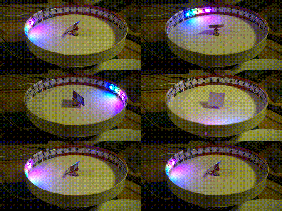
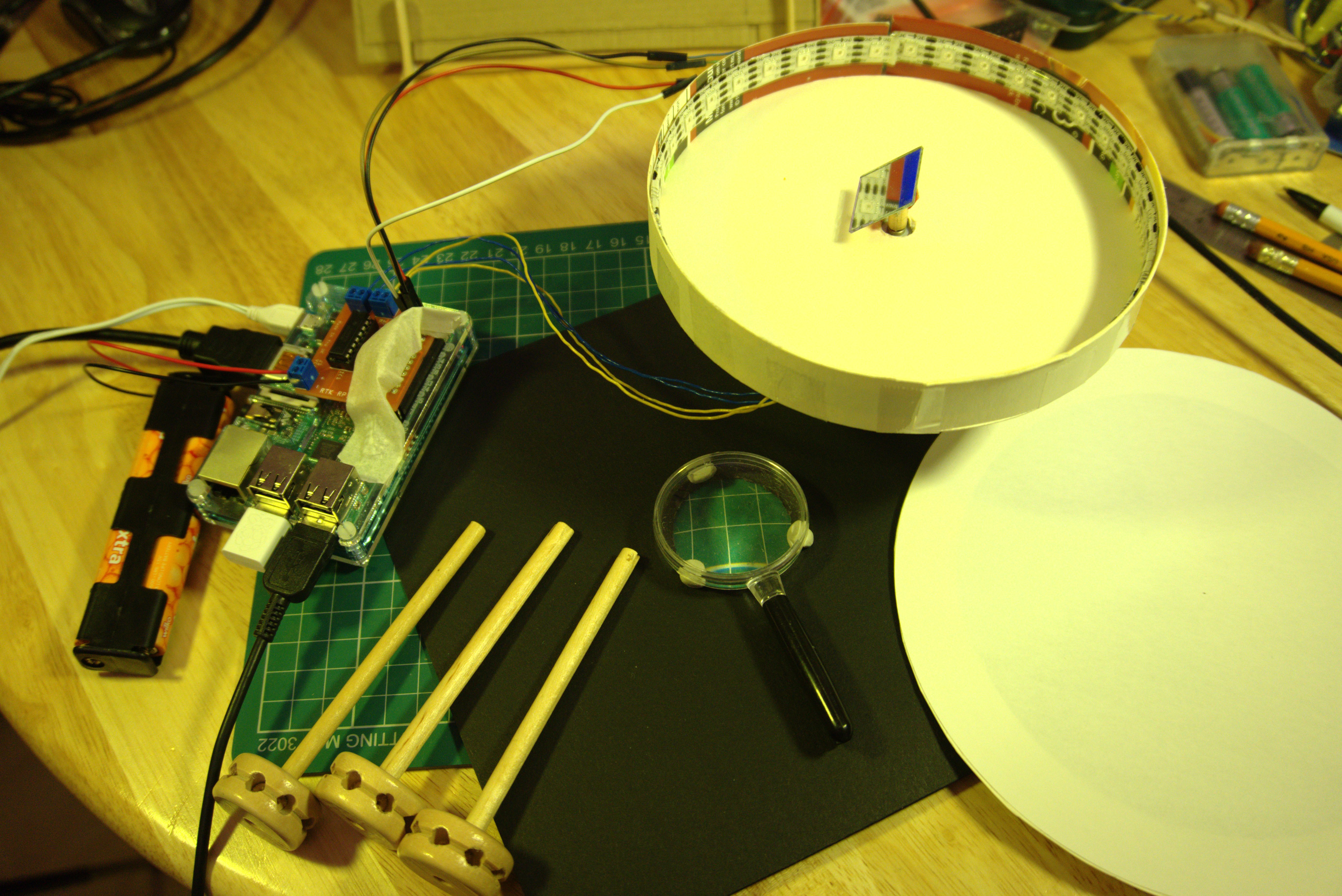
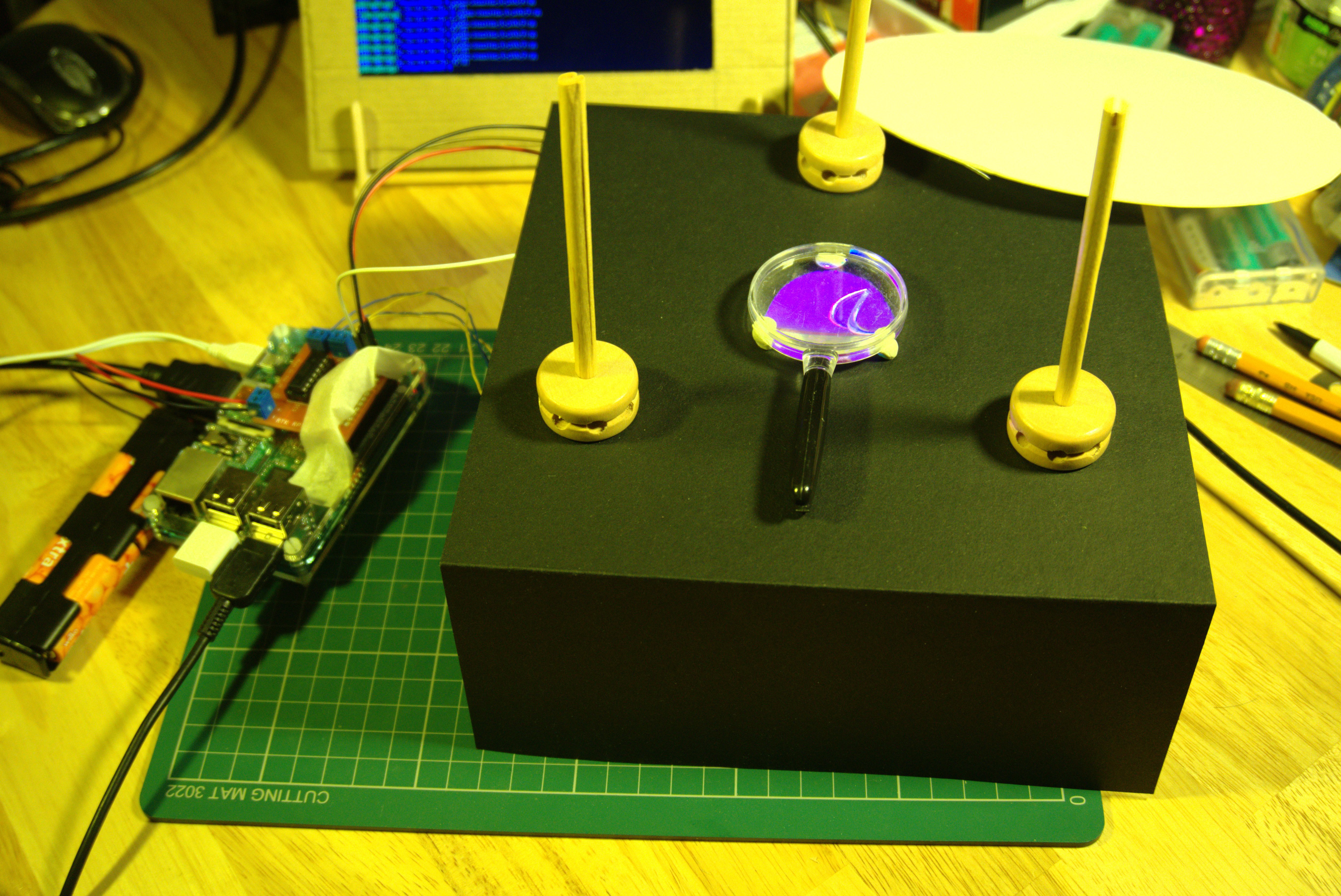
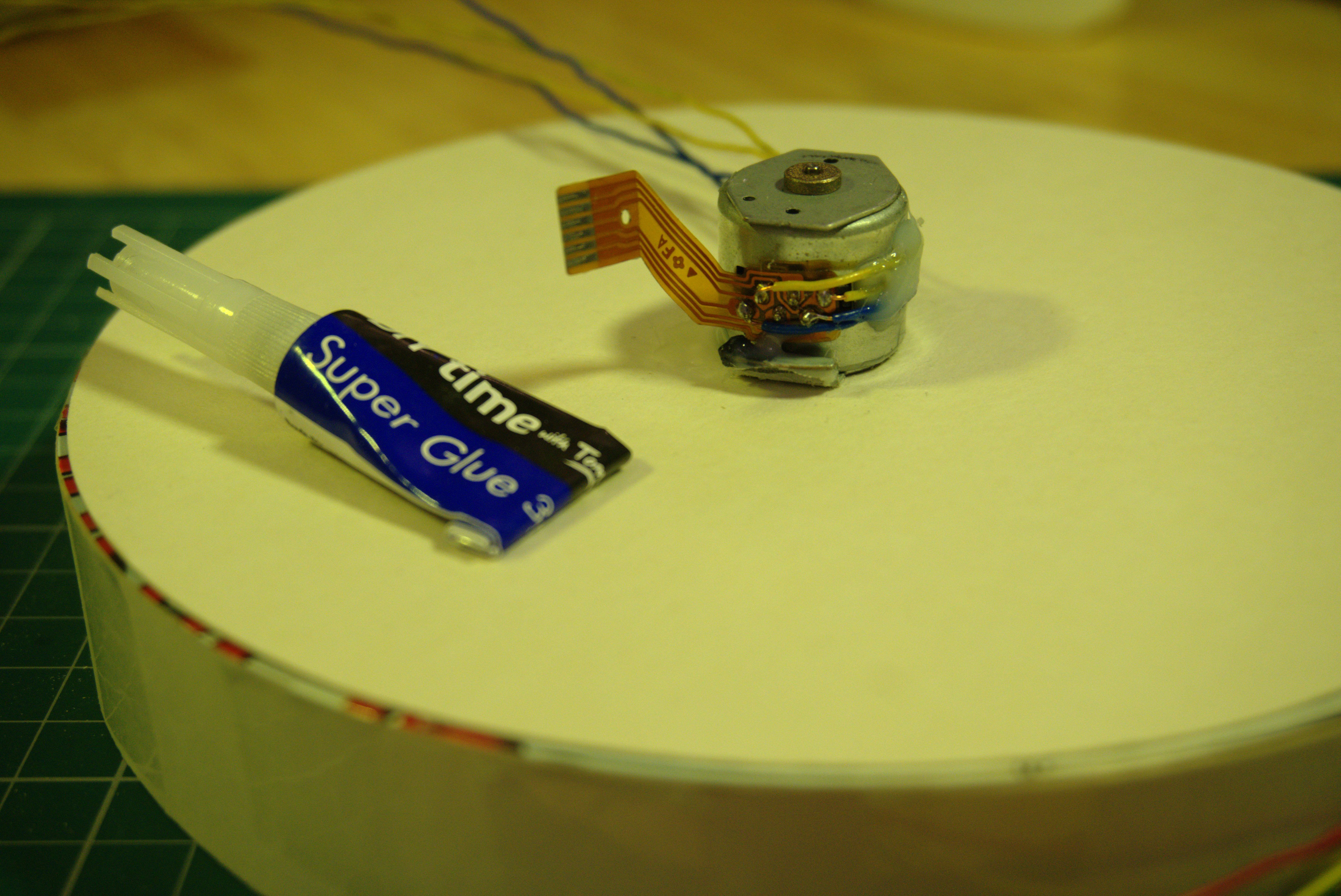
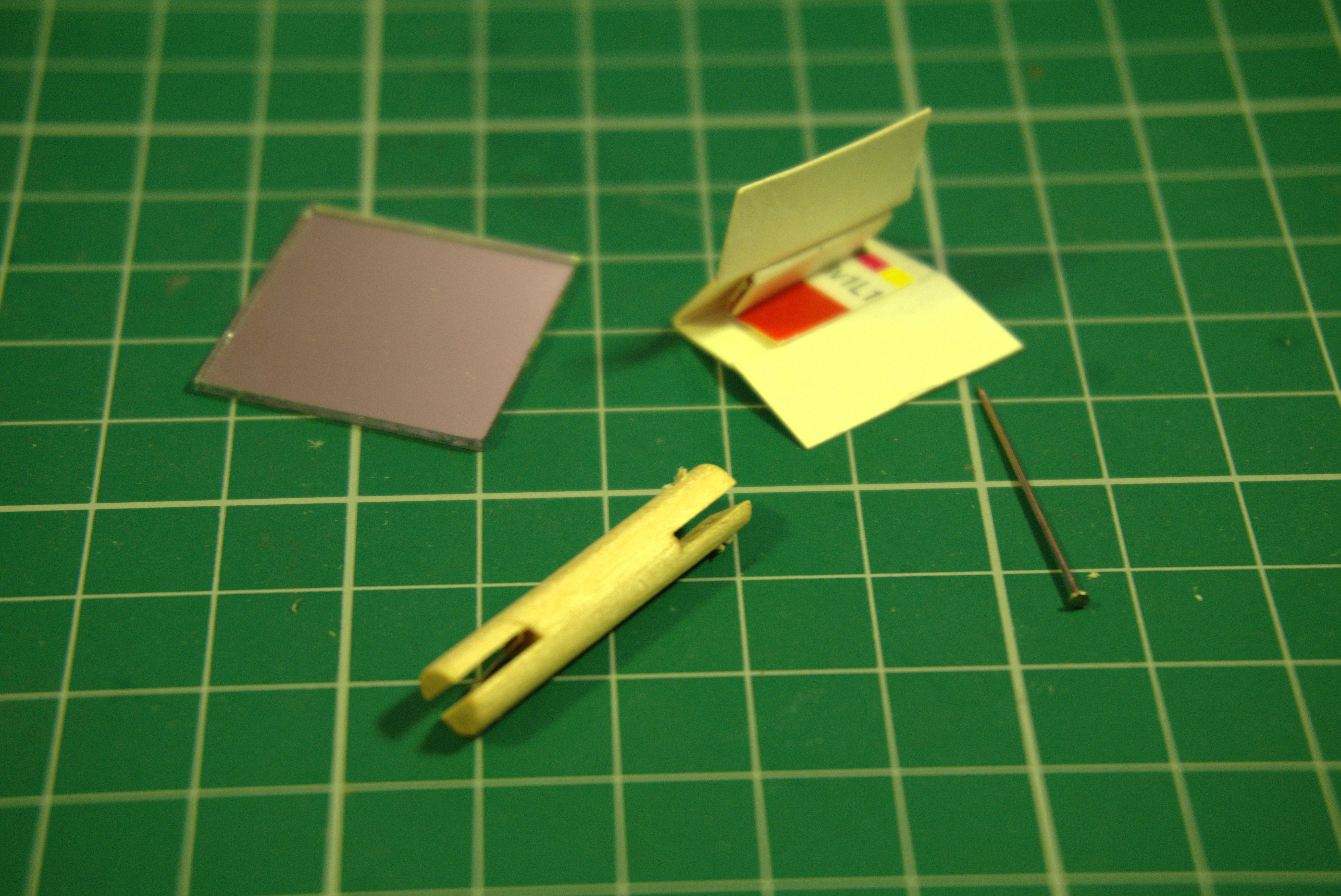
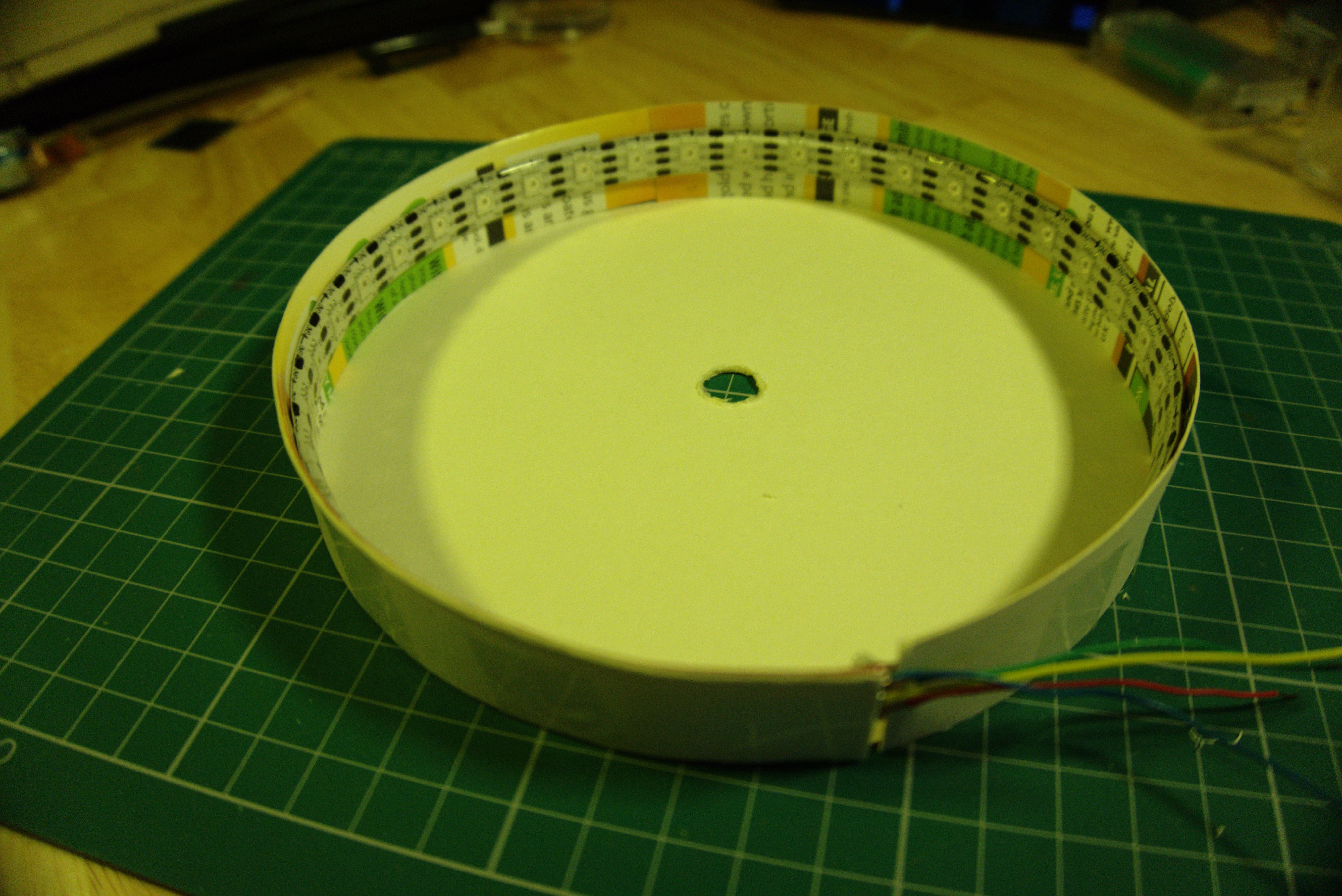
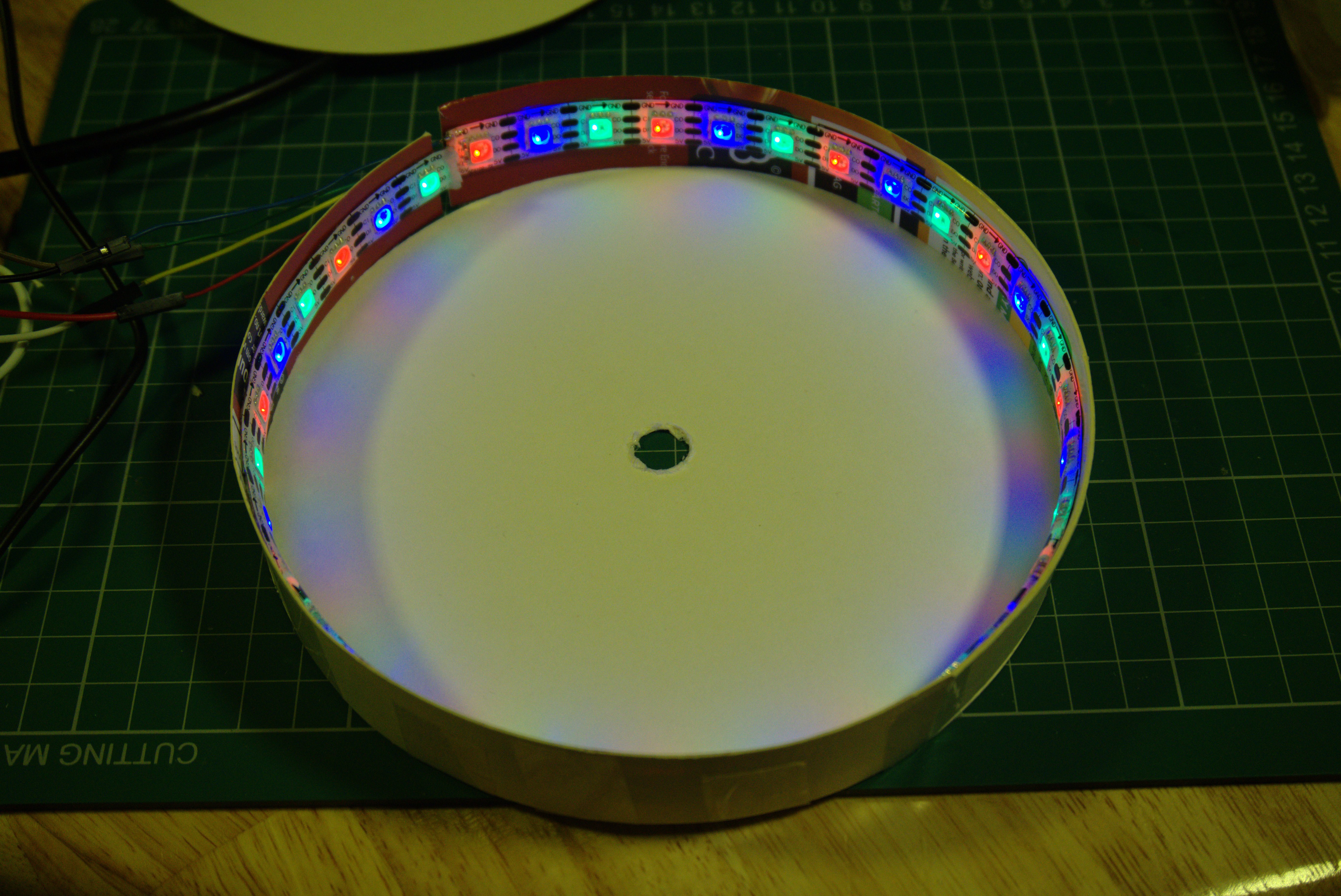
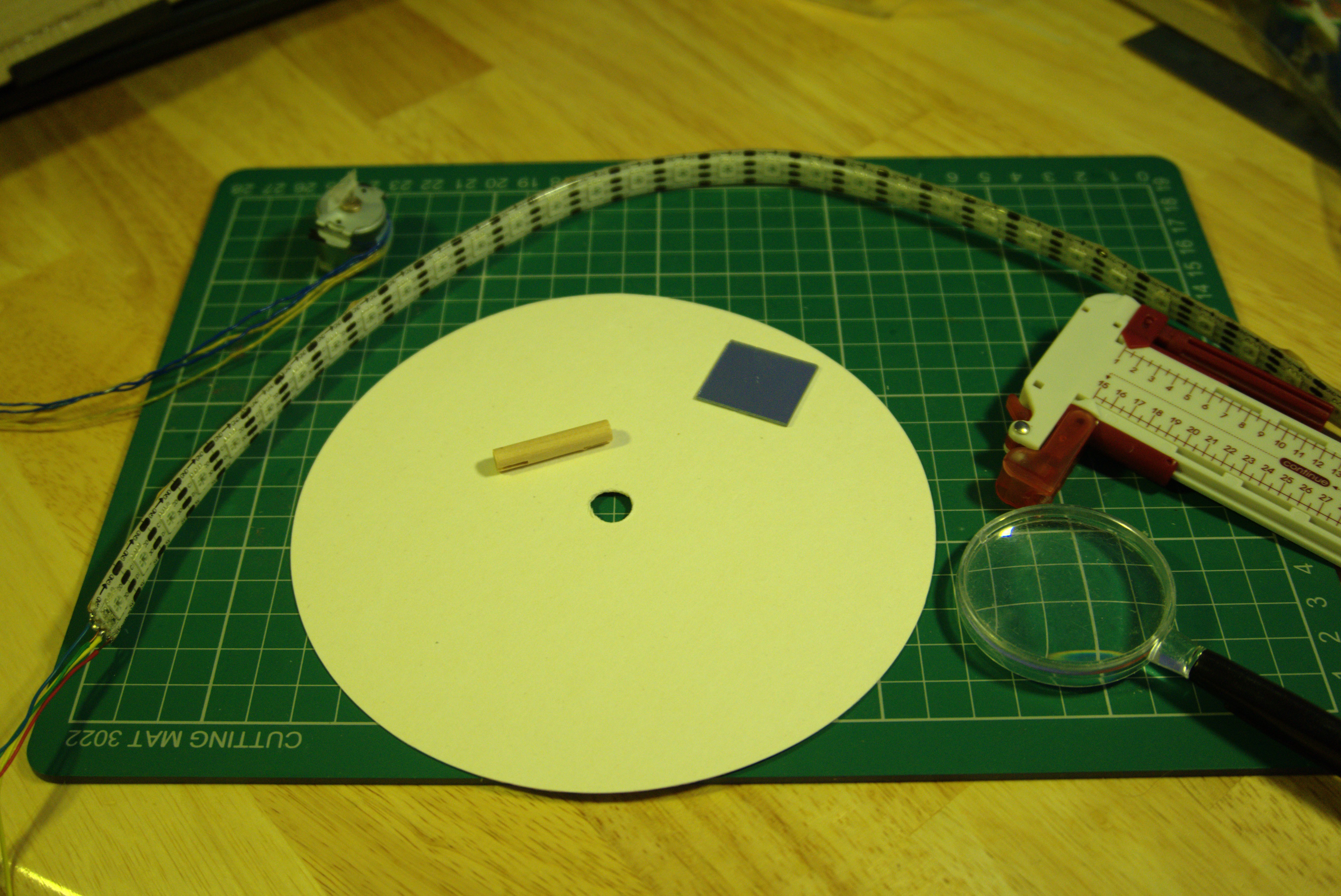
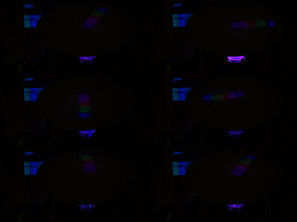 Instead this project explores using a spinning mirror to reflect the light from the LEDs in different directions to visualize the orientation data. There is a trade-off with this approach. While the angular resolution is limited only by the microstepping resolution of the stepper motor used to spin the mirror, the information conveyed in the radial direction is of very low resolution. I've used only 36 APA102 RGB LEDs, or which only 9 or fewer are visible to the mirror at any one moment. The radial displacement of each projected LED also depends on the angle of the mirror. Although this problem can be reduced using a higher density of LEDs per strip, the issue never goes away entirely.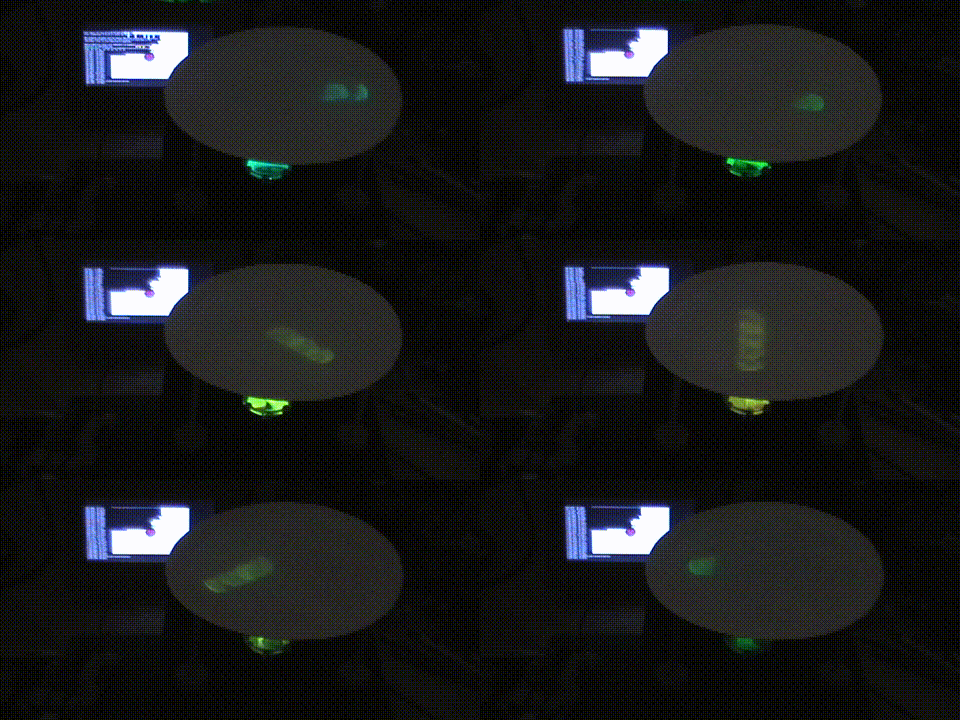
To visualize the location of the International Space Station, the longitude was mapped more or less directly to the rotation of the mirror. Latitude was mapped to the number of LEDs lit (i.e. one LED illuminates a spot on the circular paper screen for every 15 degrees of latitude between the ISS and the equator). The colour of the LEDs was also made to depend on the latitude. 90 degrees south (blue), 0 at the equator (green), 90 degrees north (red), with smooth linear colour transitions between those points. The ISS never goes further north or south than around 50 degrees, so the colours projected tend to sway between yellow and bluish-green as shown in the (x 200) time lapse gif above.
The are many directions in which I've considered taking this project:
- Different input data sources - I've been planning to add ratiometric Hall effect sensors to estimate the direction of the magnetic fields in the vicinity of the device. The projected row of LEDs would then act like a compass needle.
- Explore different surfaces on which to project: a sphere, a cone, the ceiling or a wall.
- Spin the mirror much faster for persistence-of-vision effects
- Instead of just one LED strip, try three or more LED strips along side each other in the cylinder.
- Use more than one mirror so that all the LEDs can participate all the time, instead of less than a quarter being active in the current prototype.



 blinkingthing
 Evan
Evan
 John Opsahl
 swimmingthestyx