bornach
-
Keeping it all in sync for final assembly
09/29/2018 at 19:03 • 0 comments![]()
The challenging part was microstepping the stepper motor so that it stayed in sync with the APA102 strip.
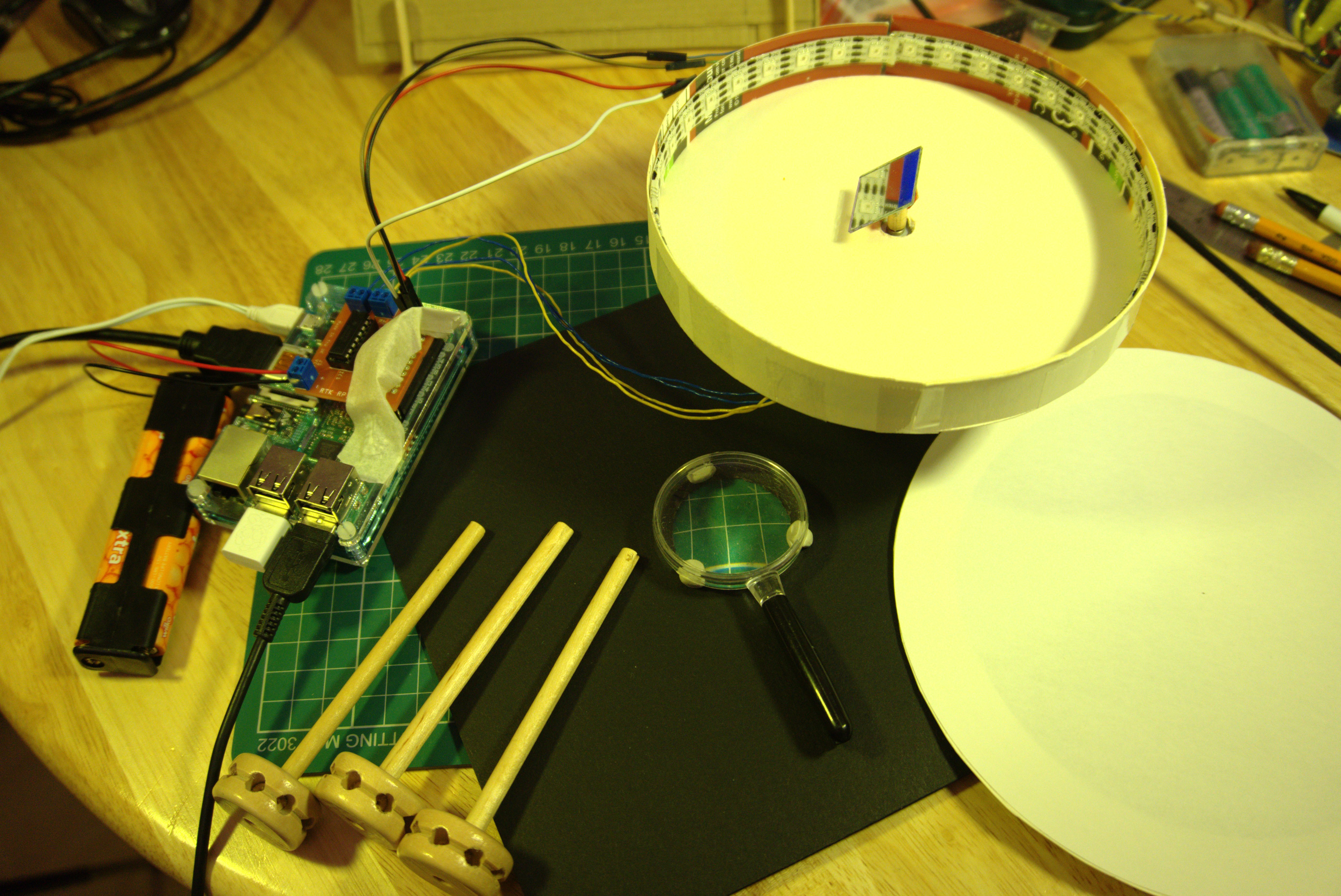
This stepper motor only has 20 steps in full rotation. If I had limited the motor control to full or half stepping, it would mean the orientation resolution would have been a 9 or 18 degrees. So I had to implement microstepping that would output a PWM to the GPIO pins controlling the SN754410NE. I couldn't use the built-in PWM of the RPi.GPIO library because it seems to be unstable and segmentation faults whenever I tried to use it for microstepping. So far I have it set to 2 degree resolution. Now for final assembly:![]()
The light from the portion of the LEDs that are illuminated should be redirected upwards by the rotating mirror that has been tilted at 45 degrees. This will need to be collimated using a hole cut in cardboard and focused with the help of a cheap magnifying glass.
![]()
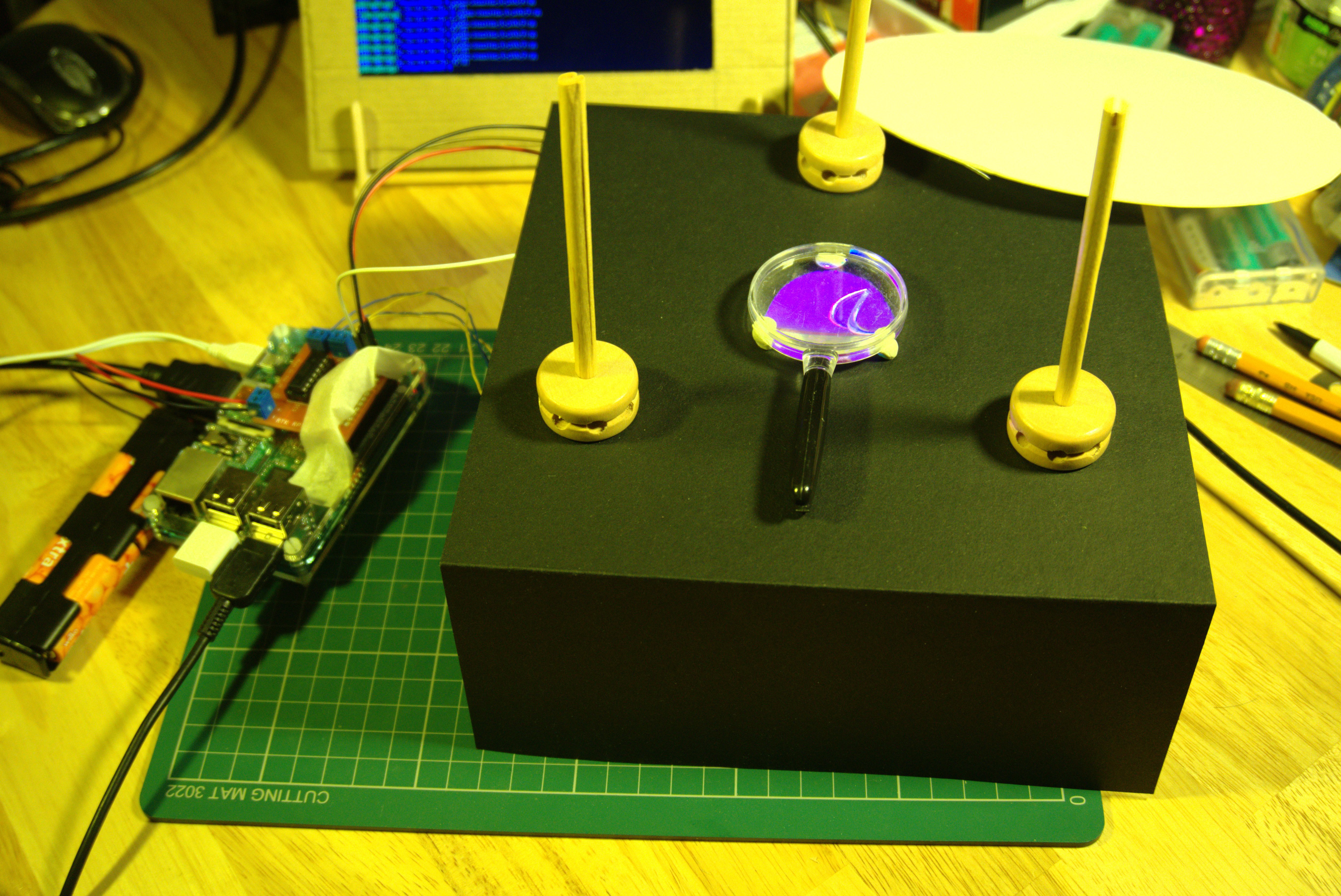
The exact geometry and lens focal length will ultimately determine how far to place the paper screen onto while the LEDs will be projected. This was also done with trial and error.
The image shows the Raspberry Pi 2 with motor driver hat -- I've taken the precaution of using masking tape to avoid accidentally shorting the pins when I attach the LED strip. -
Attaching Stepper Motor and Mirror
09/29/2018 at 18:45 • 0 comments![]()
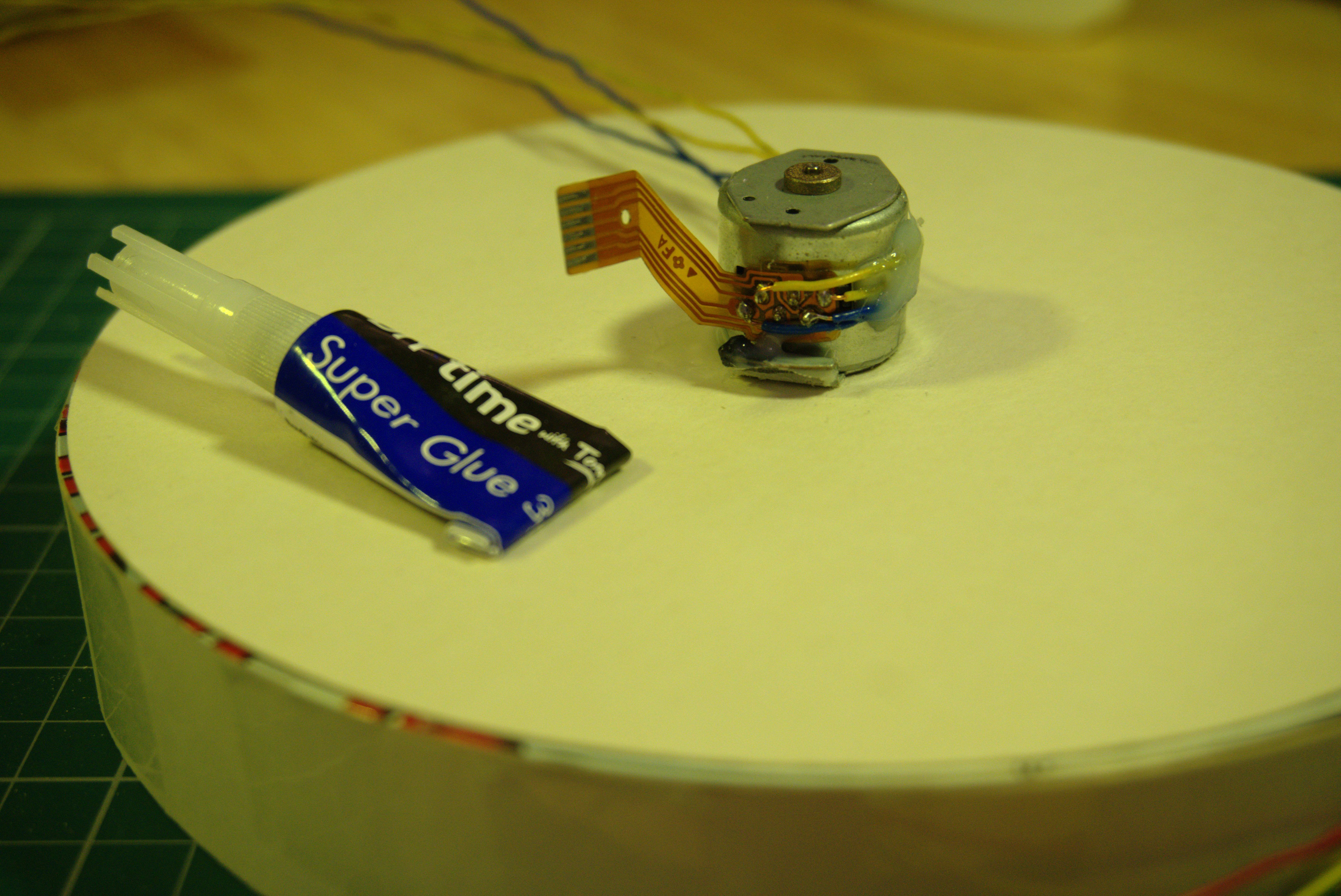
I had initially tried a more complicated motor mounting method in order to accommodate the length of the wooden shaft, but then opted to glue the stepper motor directly to the cardboard disc, and instead just trim the wooden shaft down. Had I committed to doing this from the start, I would have trimmed the shaft down first before attaching the mirror to it.
![]()
Drilling a small hole into a wooden shaft would have been much easier to do if it didn't have a breakable mirror glued to it.
-
Spinning Mirror Assembly
09/29/2018 at 18:37 • 0 comments![]()
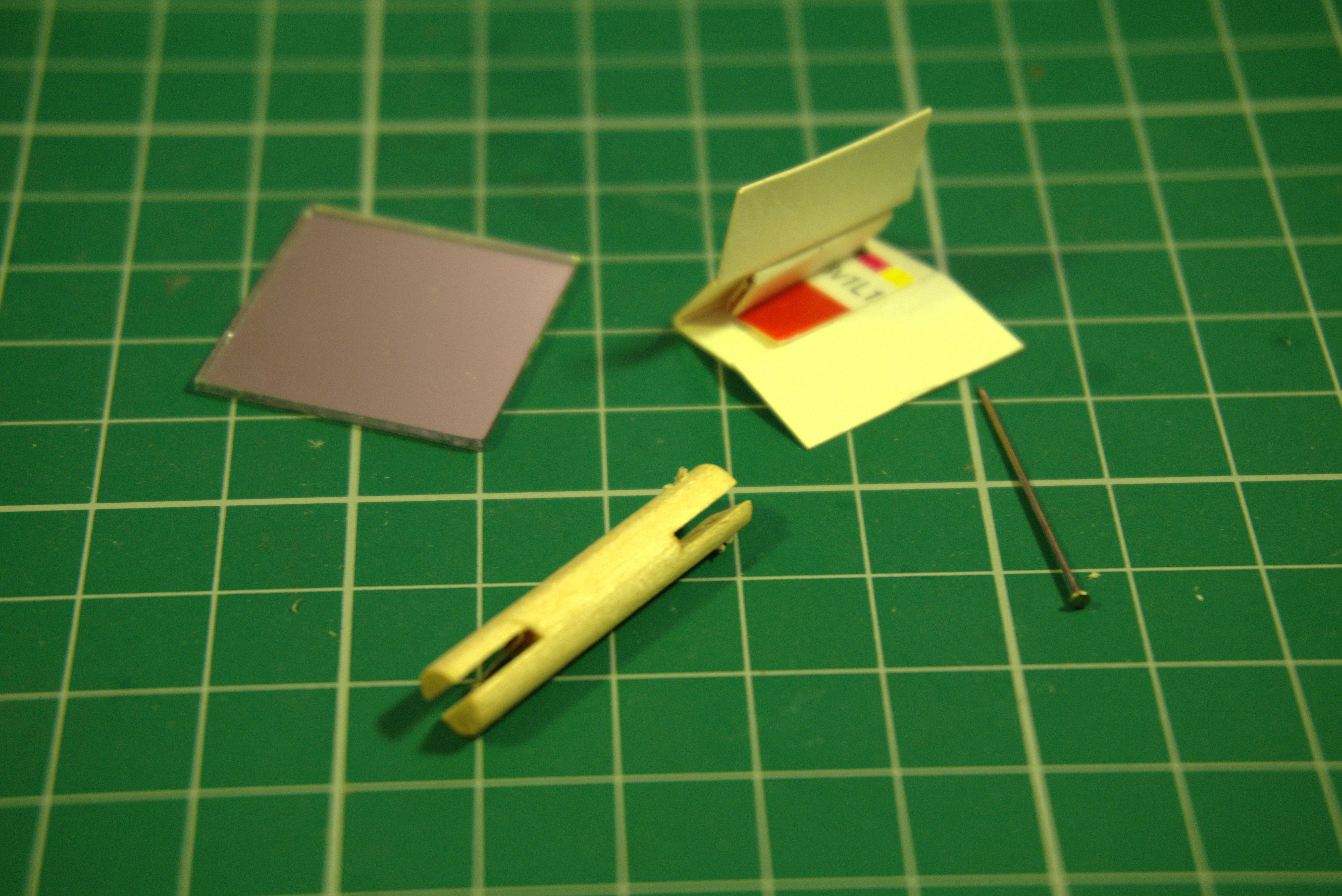
The wooden shaft already had two slots. All I had to do was drill a hole perpendicular to one slot to fit the pin that would allow the mirror to pivot.
![]()
A little trimming of the cardboard was needed to make sure that the mirror could be tilted to at least 45 degrees to the shaft. Everything is held together with two-part epoxy resin.
-
Testing the LED strip cylinder
09/29/2018 at 18:26 • 0 comments![]()
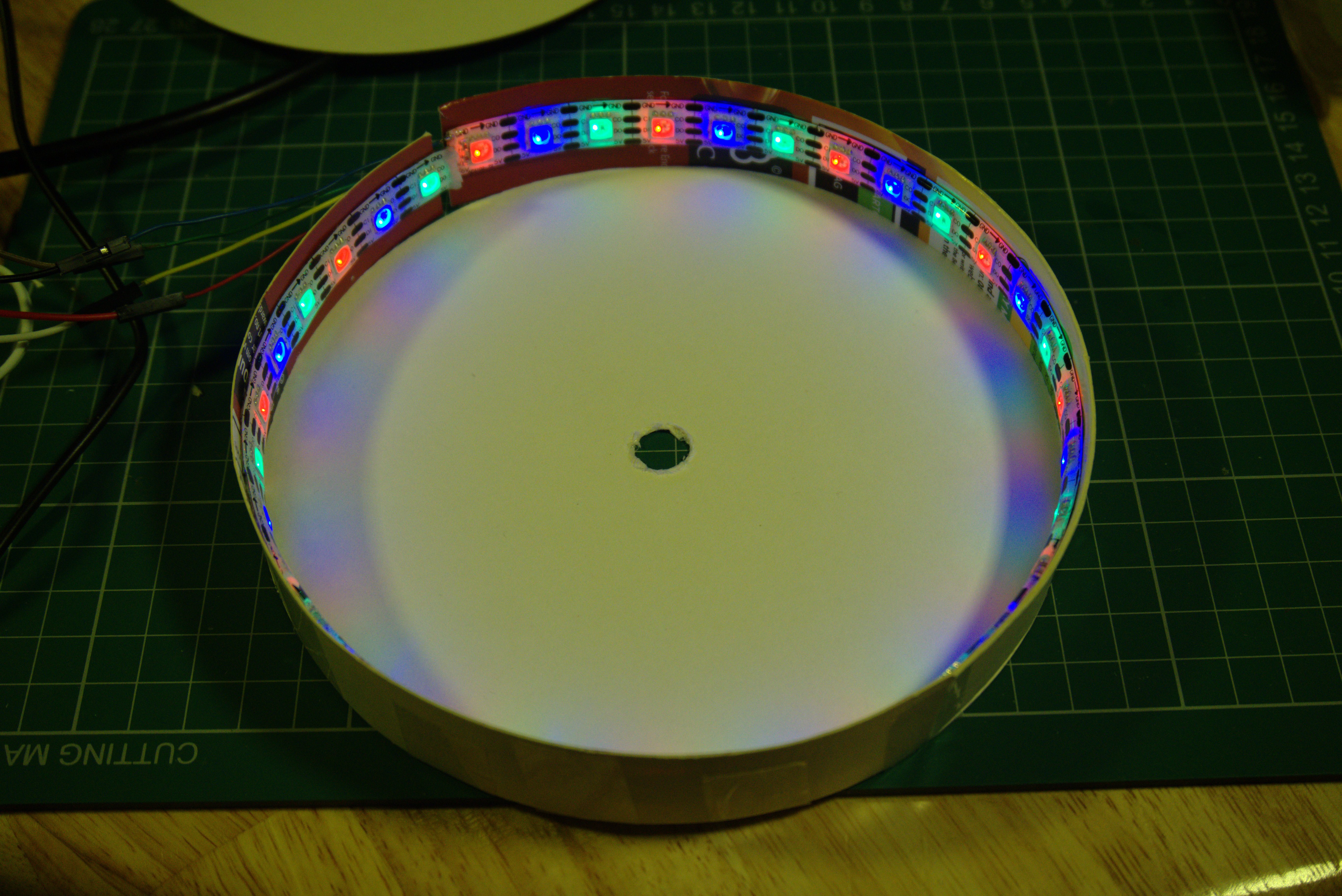
This step took a bit of trial and error. My first cylinder was too small and the beginning and end of the LED strip overlapped too much. I measured the overlap and remade a slightly bigger cylinder.![]()
It is a good idea the test the LED strip frequently after each step in the build to make sure I didn't damage anything. Here I wrote a simple APA102 test program in Python to run on the Raspberry Pi that toggles the GPIO pins to send the RGB data to the strip. This would have been more difficult to do with a WS2812 NeoPixel without the use of a prepackaged neopixel library. -
Cylinder walls
09/29/2018 at 18:15 • 0 comments![]()
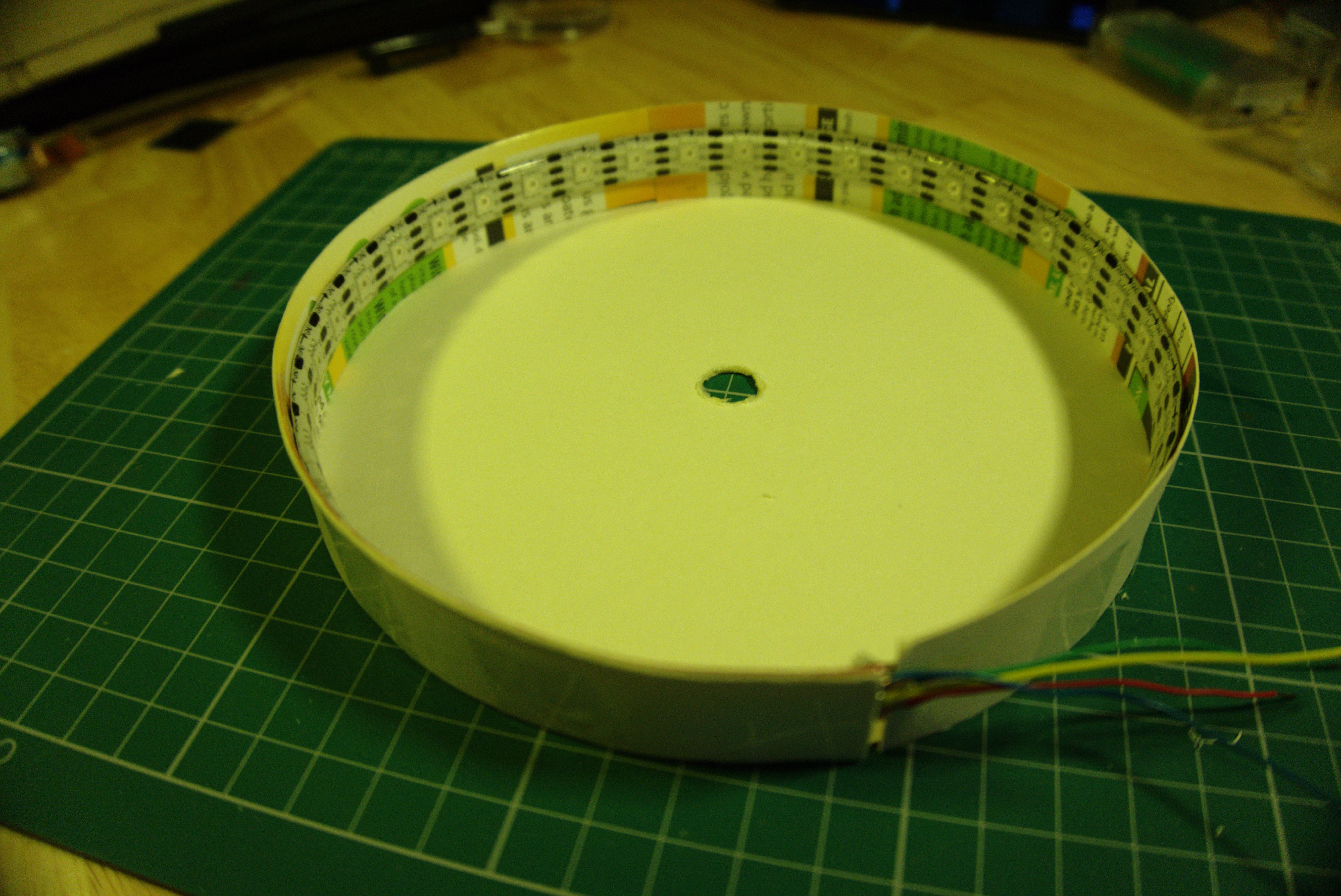
I didn't have a strip of cardboard long enough for the circumference of the disc, so taping two pieces together. The APA102 strip has an adhesive backing and will be stuck to these cardboard walls after they are taped to the disc to make a short open cylinder. It will look not very different from a Zoetrope
-
Sizing the disc
09/29/2018 at 18:04 • 0 comments![]()
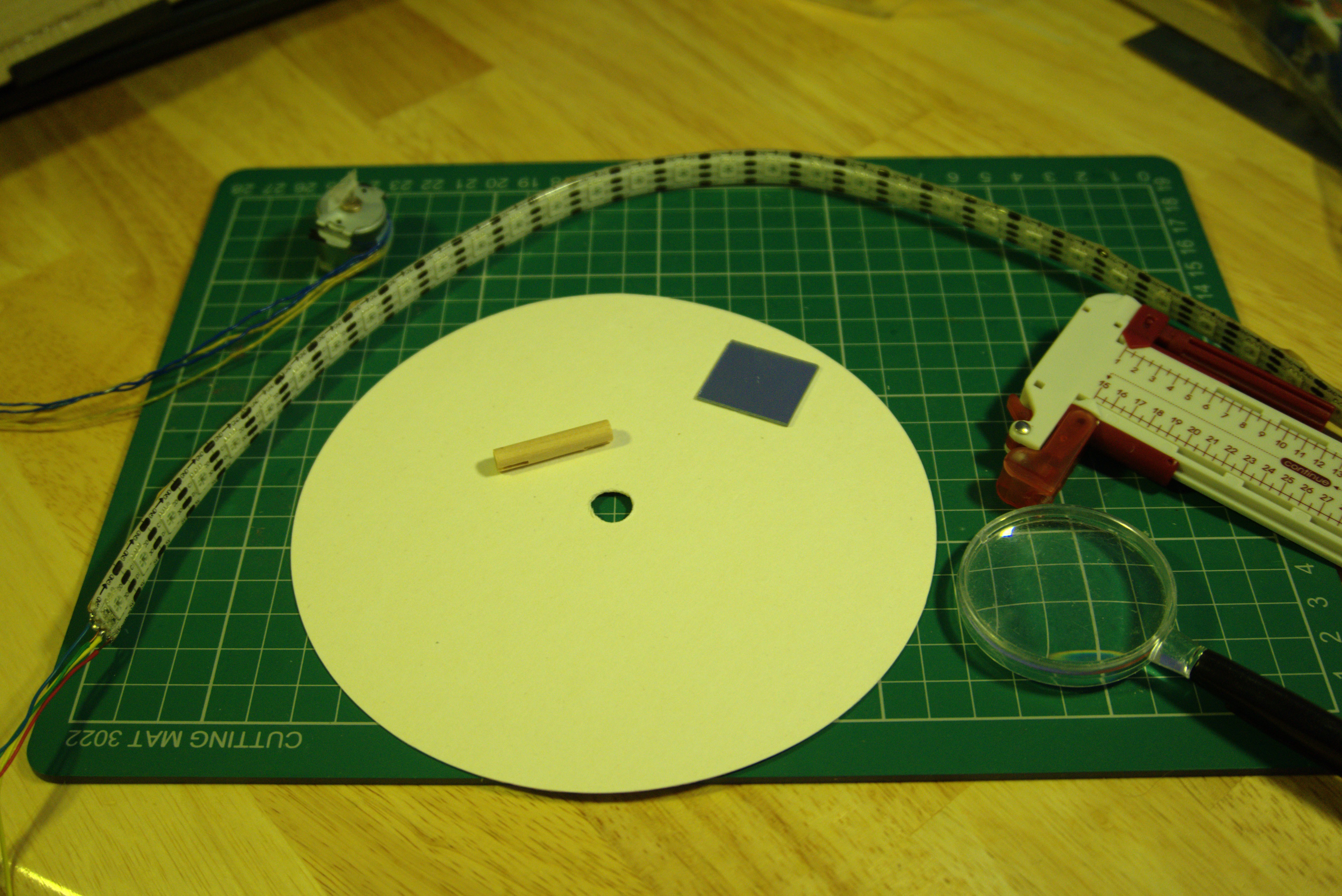
I started by measuring the length of the LED strip to figure out size of the circle. It so happened that this APA102 strip I bought on Ebay years ago had 36 LED chips. The circumference of the circle had to chosen so that LED spacing was as even as possible -- 10 degrees between LEDs. This took a bit of trial and error.
The hole in the center of the disc should be big enough to accommodate the stepper motor shaft but not too wide as the motor had to be glued to the disc.
I've soldered the wires to the stepper motor -- this is recovered from a CD-ROM drive. I had the option of wiring it as unipolar or bipolar. I chose the latter because I was going to use an H-bridge motor driver to make it spin.
Radial LED Projection ISS Tracker
A demonstration of an efficient way to use a fairly small number of addressable LEDs to convey polar coordinate information