Christoph
-
PWM works on the FPGA!
12/07/2018 at 20:55 • 0 commentsSo I managed to write a top module for the PWM module I came up with. Here it is:
module top(
  input i_clk12,
  output o_led);

reg reset = 0;
wire pwm_out;

wire clk_dc;
reg[15:0] dc = 0;
clockdivider clkdiv(i_clk12, 12000000, clk_dc);

pwm #(.bits(16)) pwm0(i_clk12,reset,16'd15999,dc,pwm_out);
always @(posedge clk_dc)
begin
  dc <= (dc == 16000) ? 0 : (dc + 4000);
end

SB_IO #(                // IO IP instance
  .PIN_TYPE(6'b011001)  // configure as output
) pin_out_driver (
  .PACKAGE_PIN(o_led),  // connect to this pin
  .D_OUT_0(pwm_out)     // output the state of "led"
);

endmodule
It cycles through 5 duty cycle levels (on per second). Reset isn't used, but that's not too critical here I guess.
This is the pwm code:
module pwm #(
  parameter bits = 4
  )(
  input clkin,
  input reset,
  input[bits-1:0] max,
  input[bits-1:0] compare,
  output out
);

reg[bits-1:0] count = 0;
reg[bits-1:0] compareLatched = 0;

always @(posedge clkin)
begin
  if(reset == 1)
    begin
      count <= 0;
      compareLatched <= 0;
    end
  else
    begin
      if(count == 0)
        begin
          count <= max-1;
          compareLatched <= compare;
        end
      else
        count <= count-1;
    end
end
assign out = count < compareLatched;

endmodule
Pins:
set_io i_clk12 21
set_io o_led 96
This is for #ICEd = an Arduino Style Board, with ICE FPGA
-
PWM
12/05/2018 at 21:24 • 0 commentsAfter some discussions in the hack/fpga chats I was able to come up with a PWM module that does what I wanted to do - in a simulation.
pwm_dn.v (the sync reset is subject to change)
module pwm #(
  parameter bits = 4
  )(
  input clkin,
  input reset,
  input[bits-1:0] max,
  input[bits-1:0] compare,
  output out
);

reg[bits-1:0] count = 0;
reg[bits-1:0] compareLatched = 0;

always @(posedge clkin)
begin
  if(reset == 1)
    begin
      count <= 0;
      compareLatched <= 0;
    end
  else
    begin
      if(count == 0)
        begin
          count <= max-1;
          compareLatched <= compare;
        end
      else
        count <= count-1;
    end
end
assign out = count < compareLatched;

endmodule
Regarding reset: there seems to be a lot of discussion about sync vs. async reset, and I haven't made up my mind about what I'd actually like. One thing that is pointed out regularly is that some FPGA prefer one over the other, behavior-wise. I don't know what the case is for the iCE40 series.
@Frank Buss pointed out this topic on stack exchange, which includes further reading:
https://electronics.stackexchange.com/questions/21696/reset-synchronous-vs-asynchronous
Then there's the assignment of out, which is not a register in the above code. A variant that was discussed is to assign the comparison result to a wire, and update that in the always block. This would make sure that it's always updated on a rising clock edge. However, it would also be delayed by one clock. All that probably doesn't matter for PWM which would usually be connected to some external device anyway.
The testbench, pwm_dn_tb.v:
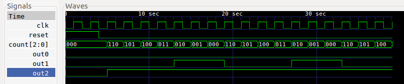
`default_nettype none

module test;

reg clk = 0;
reg reset = 0;
wire out0,out1,out2,out3,out4,out5;

always #1 clk=~clk;

pwm #(.bits(3)) dut0(clk,reset,3'd7,3'd0,out0);
pwm #(.bits(3)) dut1(clk,reset,3'd7,3'd3,out1);
pwm #(.bits(3)) dut2(clk,reset,3'd7,3'd7,out2);
pwm #(.bits(1)) dut3(clk,reset,1'd1,1'd0,out3);
pwm #(.bits(1)) dut4(clk,reset,1'd1,1'd1,out4);

initial
  begin
    $dumpfile("dump.vcd");
    $dumpvars(3);
    reset = 1;
    #4
    reset = 0;
    #35
    $finish;
  end

endmodule
and some simulator output in gtkwave:
Reset is apparently handled correctly, the counters count down, and full-off and full-on work ok as well as intermediate values.
The other two dut's (for out3 and out4) are 1-bit devices just to see if the code even works with 1 bit resolution (on/off) - and it does.
So far I'm happy with this.
-
clock divider, makefile, simulations and gtkwave
12/03/2018 at 21:55 • 0 commentsI found a great makefile in the icestorm examples. It can do synthesis, place and route, packing, run a simulation (pre- and post-synthesis) and program your board. Since users and hardware are different, it might need some adjustments here and there. The original file is here: https://github.com/cliffordwolf/icestorm/blob/master/examples/icestick/Makefile
It's actually pretty simple and saves a ton of work on the command line - just like it's supposed to.
I decided to take my simple clock divider code to see what it actually does (because I really don't remember exactly): write a test bench, run a simulation and look at the results in gtkwave.
Again, the clockdivider.v code I used earlier (and we'll see why it might be bad code):
module clockdivider #(
  parameter bits = 32
  )(
  input clkin,
  input[bits-1:0] div,
  output clkout
);

reg [bits-1:0] count = 0;
always @(posedge clkin)
begin
  if(count == 0)
    count = div;
  count = count - {{bits-1{1'b0}},1'b1};
end

assign clkout = (div == 1'b0) ? 1'b0 :
                (div == 1'b1) ? clkin :
                (count == {bits{1'b0}});

endmodule
Let's put this under test with 4 bits, and divide the clock by 4.
clockdivider_tb
`default_nettype none

module test;

reg clk=0;
wire clkout;

always #1 clk=~clk;

 clockdivider #(.bits(3)) dut0(clk,3'd4,clkout);

initial
    begin
    $dumpfile("dump.vcd");
    $dumpvars(3);
#20
    $finish;
    end

endmodule
Now, with the makefile from the icestorm toolchain, getting simulation output is as simple as
make clockdivider_tb.vcd
gtkwave dump.vcd &
The makefile rules used here are:
%_tb: %_tb.v %.v
    iverilog -o $@ $^

%_tb.vcd: %_tb
    vvp -N $< +vcd=$@
The first one will use the %.v and %_tb.v files (where % is "clockdivider") to build the testbench executable (clockdivider_tb), using iverilog. This executable is then run by vvp using the second rule. This second rule is the one we triggered on the command line. I'm not sure what vvp actually *does*, because simply running the testbench executable will also generate the desired vcd file (unless it causes subtle changes that I'm not able to spot).
The testbench dumps values in dump.vcd, which can be viewed using gtkwave. The result:
The signals can be dragged into the waves window for inspection. The first pulse on clkout was a bit unexpected, but that's probably because we don't have a proper reset for the device. Anyway, it seems to divide the clock by 4, which is what I wanted to achieve. There's probably a lot of room for improvement, but I'm a mechanical engineer - cut me some slack.
-
#2: still blinky, but now adding a PLL clock
11/30/2018 at 20:22 • 0 commentsSo with the first blinky test behind me, I wanted to get away from the fixed 12 MHz external oscillator. The HX1K has a PLL for that! For someone with a background in mechanical engineering, the act of creating a faster clock than we originally had is somewhat mind-blowing, so let's go for 24 MHz.
Instead of making the mistake of reading the datasheet and then failing to make sense of it, let's use icepll to create code for the PLL:
icepll -i 12 -o 24 -f pll.v -m
here's the output, which also kinda describes what the command line requests:
F_PLLIN:    12.000 MHz (given)
F_PLLOUT:   24.000 MHz (requested)
F_PLLOUT:   24.000 MHz (achieved)

FEEDBACK: SIMPLE
F_PFD:   12.000 MHz
F_VCO:  768.000 MHz

DIVR:  0 (4'b0000)
DIVF: 63 (7'b0111111)
DIVQ:  5 (3'b101)

FILTER_RANGE: 1 (3'b001)

PLL configuration written to: pll.v
The file that was created contains a ready to use PLL module.
pll.v
/**
 * PLL configuration
 *
 * This Verilog module was generated automatically
 * using the icepll tool from the IceStorm project.
 * Use at your own risk.
 *
 * Given input frequency:        12.000 MHz
 * Requested output frequency:   24.000 MHz
 * Achieved output frequency:    24.000 MHz
 */

module pll(
	input  clock_in,
	output clock_out,
	output locked
	);

SB_PLL40_CORE #(
		.FEEDBACK_PATH("SIMPLE"),
		.DIVR(4'b0000),		// DIVR =  0
		.DIVF(7'b0111111),	// DIVF = 63
		.DIVQ(3'b101),		// DIVQ =  5
		.FILTER_RANGE(3'b001)	// FILTER_RANGE = 1
	) uut (
		.LOCK(locked),
		.RESETB(1'b1),
		.BYPASS(1'b0),
		.REFERENCECLK(clock_in),
		.PLLOUTCORE(clock_out)
		);

endmodule
I can now use pll.v in my top-level module.
Since I now have two clocks, I also want two LEDs. Since there's an RGB LED on my board, let's go for that.
top.pcf
set_io clk_12M 21
set_io pin_ledr 97
set_io pin_ledg 99
So there's still the input from the external oscillator, but this time I have two pins for - well - two LEDs.
The top level module now contains
- two pin drivers
- a pll
- two clock dividers (see https://hackaday.io/project/162557-fpga-dabbling/log/156515-1-blinky for clockdivider.v)
- and some glue code to put everything together
To me it's pretty obvious that a slightly different structure would have made it easier to read.
top.v
module top (
  input clk_12M,
  output pin_ledr,
  output pin_ledg
);

reg led_r = 0;
SB_IO #(
  .PIN_TYPE(6'b011001)
) pin_ledr_driver (
  .PACKAGE_PIN(pin_ledr),
  .D_OUT_0(led_r)
);

wire clk_r; // for pin_ledr
clockdivider #(.bits(28)) div_r(
  .clkin(clk_12M),
  .clkout(clk_r),
  .div(28'd12000000)
);

always @(posedge clk_r)
led_r = ~led_r;

wire clk_24M;
pll pll(
  .clock_in(clk_12M),
  .clock_out(clk_24M)
);

reg led_g = 0;
SB_IO #(
  .PIN_TYPE(6'b011001)
) pin_ledg_driver (
  .PACKAGE_PIN(pin_ledg),
  .D_OUT_0(led_g)
);

wire clk_g; // for pin_ledr
clockdivider #(.bits(28)) div_g(
  .clkin(clk_24M),
  .clkout(clk_g),
  .div(28'd12000000)
);

always @(posedge clk_g)
led_g = ~led_g;

endmodule
synthesize, place&route and pack:
yosys -p 'synth_ice40 -top top -blif top.blif' top.v clockdivider.v pll.v
arachne-pnr -d 1k -o top.asc -p top.pcf top.blif
icepack top.asc top.bin
download:
iceprog -S top.bin
Double blinky indeed! Two LEDs are now blinking at two different frequencies, and they're so bright that I unplugged the board again. I'll need some sort of PWM to dim that. An obvious choice for the next experiment.
-
#1: blinky
11/30/2018 at 19:38 • 0 commentsAfter installing the icestorm tools, arachne-pnr, nextpnr and yosys (which all worked out of the box, apart from some more packages to download), I modified some very old blinky verilog code that was originally written for #DIPSY to work with the board at hand. It was mainly just a bunch of pin assignment changes and using a different clock source.
My blinky code consists of two modules:
clockdivider.v
module clockdivider #(
  parameter bits = 32
  )(
  input clkin,
  input[bits-1:0] div,
  output clkout
);

reg [bits-1:0] count = 0;
always @(posedge clkin)
begin
  if(count == 0)
    count = div;
  count = count - {{bits-1{1'b0}},1'b1};
end

assign clkout = (div == 1'b0) ? 1'b0 :
                (div == 1'b1) ? clkin :
                (count == {bits{1'b0}});

endmodule
This creates a down-counter with given bit count and reload value. When it reaches zero, it reloads the internal counter with the reload value and starts over. I have no idea if this is good code, or if it's even off by one or whatever. But it seems to do the job.
Next is the top-level module that takes an input clock, feeds it into a clockdivider (see above) and outputs the divided clock to an output:
top.v
module top (
  output pin_led,
  input clk_12m
);

reg led = 0;
SB_IO #(             // IO IP instance
  .PIN_TYPE(6'b011001)  // configure as output
) pin_out_driver (
  .PACKAGE_PIN(pin_led), // connect to this pin
  .D_OUT_0(led)           // output the state of "led"
);

wire clkout;
clockdivider #(.bits(28)) div(
  .clkin(clk_12m),
  .clkout(clkout),
  .div(28'd12000000)
);

always @(posedge clkout)
led = ~led;

endmodule
Again, no quality claims here. But - again - it does the job!
My board has a 12 MHz oscillator and an LED connected like so:
top.pcf
set_io clk_12m 21
set_io pin_led 96
With icestorm, synthesis, placie&route and "packing" (I don't know what the correct technical term is) are three command lines:
yosys -p 'synth_ice40 -top top -blif top.blif' top.v clockdivider.v
arachne-pnr -d 1k -o top.asc -p top.pcf top.blif
icepack top.asc top.bin
Now there's a bin file to be downloaded to the FPGA's config memory. I couldn't figure out how to program my board's flash chip, so this is for SRAM config:
iceprog -S top.bin
I have this dev rule:
/etc/dev/rules.d/53-lattice-ftdi.rules
ATTR{idVendor}=="0403", ATTR{idProduct}=="6010", MODE="660", GROUP="dialout"quality level: does the job on my laptop.
And I had blinky!
FPGA dabbling
I don't need an FPGA for anything but the fun of experimenting with it.