shane.snipe
-
Reving up for Version 17 - A fix list
06/17/2019 at 02:03 • 0 commentsWell our laser cutter at the Fox.Build makerspace in St. Charles went sideways for a while and I did not have confidence that I could make good parts. It seems to be back on line so I am going to take another swing at this. The items I had concerns about are:
1) Too much friction. Mostly because the gears are too wobbly. The 3D printed axles worked pretty well but the pin to hold them in place was never done right.
--- To reduce part count, I will look at making a 3D printed axle which collapses on it self to get through the hole and then splays out to keep it in place on the other side. It may take some cut and try as my old Japanese boss used to say but I could save 8 parts and make assembly as snap, (Pun intended.)
2) More could be done to lock the board in place.
3) I am considering the worth of using better drivers. The L293D are the cheapest drivers on the planet at 0.25 but I think I am losing a volt. I might pay $0.75 extra to have a snappy robot. Maybe the mechanics can make it efficient enough that I will not need it but it is on the radar.
4) I want to implement a BMS. I am always concerned about running my expensive batteries into the ground. If you deplete the Li ion batteries too much, they will stop working or possible explode when charged.
-
Version 16 Prebuild Fixes
02/16/2019 at 15:26 • 0 commentsElectronics
Tested the photo diode sensors on Version 15 and was not seeing a high enough voltage for the ESP8266 to get the high input. Decided to run the the resistor before the sensor instead of after. Breadboarding it showed promise and so I redid the board. I also had the wrong pitch on the motor connectors so I changed it from 1.25 pitch to 1.5 mm pitch. OSH Park set a notice that they are shipping so I need to get the rest of the changes implemented.
Acrylic laser cut parts
Our laser seems to be losing a little steam. Unfortunately everything was dialed in for 10mm/s and 80%. I need to find the new sweet spot. The areas of poor fit from V15 that I will fix and release a new dxf are as follows:
1) Shaft fit for the motor gear and space was too tight. Add a 0.1 negative sew compensation to see if it helps.
2) Make the board holder z height line to line instead of the 0.3mm clearance.
Lastly, I still have not figured out how to manage the laser cut files well. I like to modify in Fusion 360 because the push pull feature is cool, even if there is no design history. However, they can not output a full assembly drawing to a DXF. It can output an individual sketch in DXF but I want to keep the relative spacing for he assembly.
So the workflow is to make the adjustments in Fusion and then expect the Step file. Import it to Onshape, make a drawing and then export the DXF. Here is the link.
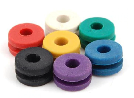
Grommets
The tatoo grommets I used for feet are awesome. I tried to replace the drive gear clip with them and it seams to be working very well. This will be one of the main none electronics parts.
or Allexpress
The new axle/gear holders are working great. We just reverted our Prusa MK2.5S to direct drive so I hope the holes do not get filed in like last time. The shape is perfect though so I hope I the print better.
-
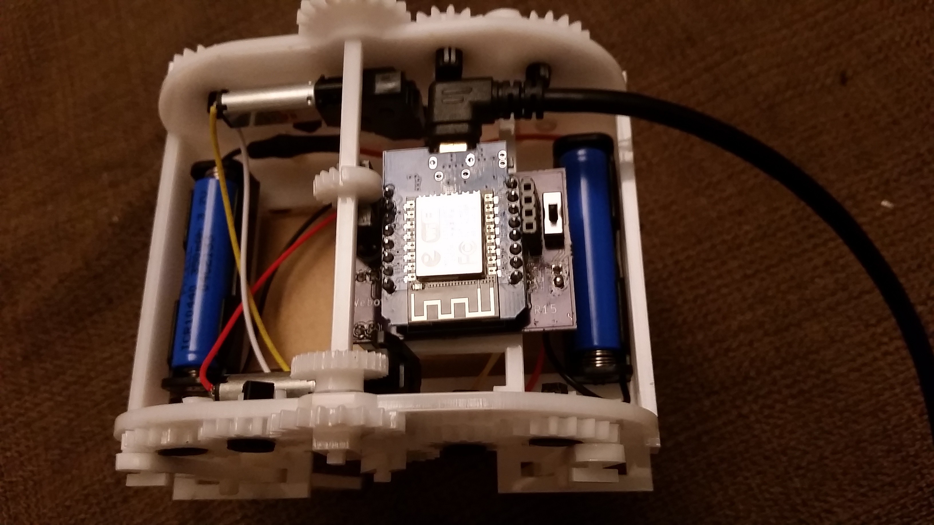
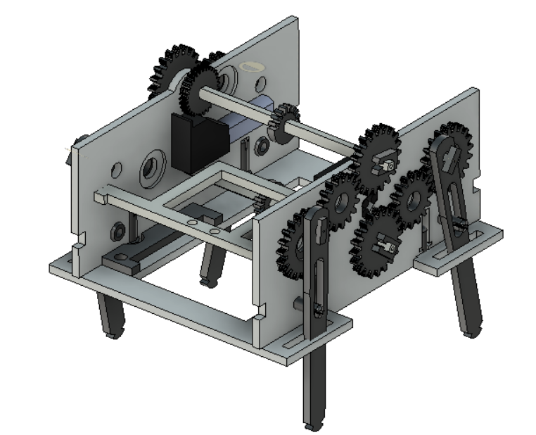
Build Report Version 15
02/04/2019 at 05:50 • 0 commentsOverall it has been a success. I tried Kicad for the first time and the board is largely functional. The new 3D printed fastener concept is working well and the gears are held in better than they have ever been.. But as I mentioned before, it is all in the tenths of a mm and here are things that need to be changed for version 16.
![]()
![]()
PCBI have gotten the 1.25 pitch instead of 1.5 pitch for the connector. It kind of works but I have to bend the pins to force it. I will fix it today.
However, the big success was the 7805/2 Li ion battery combination. The motors now have just the right speed. It is awesome.
It looks like i may need to put the resistor before the photodiode instead of after. This will allow a higher voltage when the photodiode provides a high signal.
Acrylic Frame
Our laser cutter seems to be losing some steam. I cleaned the lens but could no longer cut at 10 mm/s. This means all of the dialed in parts get a little wonky.
1) Shafts were a little tight for the motor gear and spacer. Need to open it up by a tenth.
2) Encoder is a little loose on the shaft. Tighten it by a tenth.
3) Motor fit in the wall was awesome.
4) Board holder was too loose in the vertical direction. I had 0.3mm slop. Combined with 0.2 mm
kerf it was sitting on a 10-20 degree angle and I had to glue it. Will go back to line to line.
Fasteners
This was my second round with the 3d printed gear axle/holders.
The play in the axial direction is perfect.
The window in the 3D printed parts to fit in the clip is getting covered over in the print and I need to file it. I works pretty good after filing but that is not idea. Maybe I will make the window bigger in the radial direction by 0.4mm.
The shaft clips are breaking. There is not enough flex. Increase the radius at the root of the U by 0.2mm. Replaced it with a foot (tatoo grommet) and it seems to work well. Might be a permanent fix.
Here's to round 16!
-
Battle of the tenths
01/22/2019 at 02:32 • 0 commentsCan you believe tenth of a mm can make a huge difference. It will make the difference between a loose fit and that satisfying perfect press.
So I tried out my new fasteners and they worked better than my creations usually do without tweaking. The holes were to small because 3D printed holes shrink more than I ever compensate for so I will just make them bigger. To test the pieces I used some 1.8 instead of 2.7mm acrylic and the gears spun really well. They could be a half mm more snug to the face.
The battery holding scheme is awesome. One plastic rivet and a fence. Perfectly satisfying design.
Here is a list of tweaks for this next run:
1) 0.15 mm offset for the clips to hold on the gears.
2) 0.1mm wider ledge for the T-Clips to hold the legs in place.
3) 1mm bigger holes in the 3D printed axles.
4) Added the straps to the dxf.
5) Rounded the sharp corners on the walls for fun.
I also started to get the Fusion 360 part tree. To move or copy a component you need to highlight it on the tree not the screen. Make a sketch, then a component and copy the component for multiple copies that can be edited from one sketch and moved independently. I was making multiple sketches for multiple parts. I meant lots of work if I wanted to change something.
One more item was that I found a dxf converter so at least i do not have to go back to onshape.
https://cloudconvert.com/dwg-to-dxf
Here is the latest update. I will put it in the files as Version 15.1
-
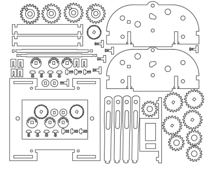
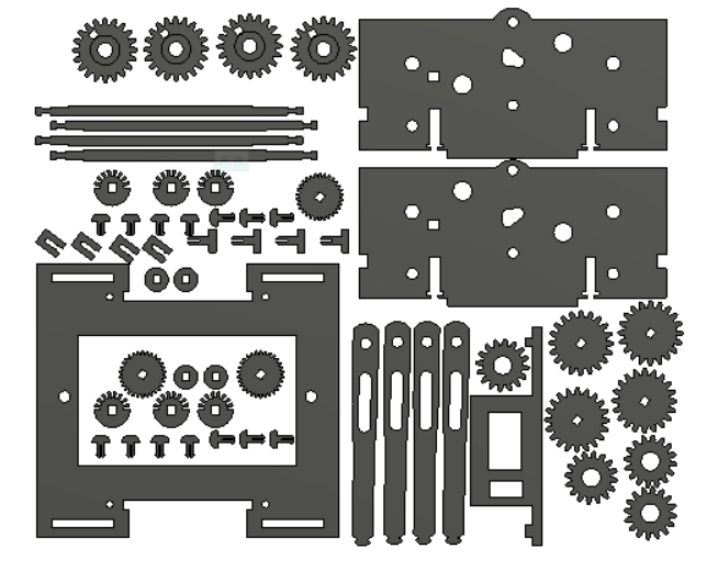
Version 15 Laser Trial
01/20/2019 at 17:49 • 0 commentsI have completed my CAD to do list. I like the way I can work in Fusion but I have not found a good work flow to get the parts into a sheet form for laser cutting. I ended up exporting a DXF of each part, saving them all in one sketch. Extruding them all. Making a drawing. Saving the dwg. Not being able to save the dxf. Export the step file of the extruded drawing. Importing it into ONSHAPE. Making a drawing and saving the DXF. THERE HAS GOT TO BE A BETTER WAY!!!! In Solidworks I had an assembly of the laser cut layout. If I changed something in the model, it would change in the laser cut assembly and I would just output a dxf. The drawing would update automatically.
In any case, here are the changes I made. It is a big rev so I hope it works.
1) Changed from proprietary hardware to 3D printed axles and laser cut spring clips. I printed out the parts but my printer was not having the best of days. We will change the Prusa back to direct drive and I think it will do better. I may need to open up the holes. I had to do a fair bit of filing to get in the spring clips.
2) Added holes for plastic rivets to hold down the batteries.
3) Change the board holder. Thanks to Kicad's mechanical output, I think it is in the perfect place.
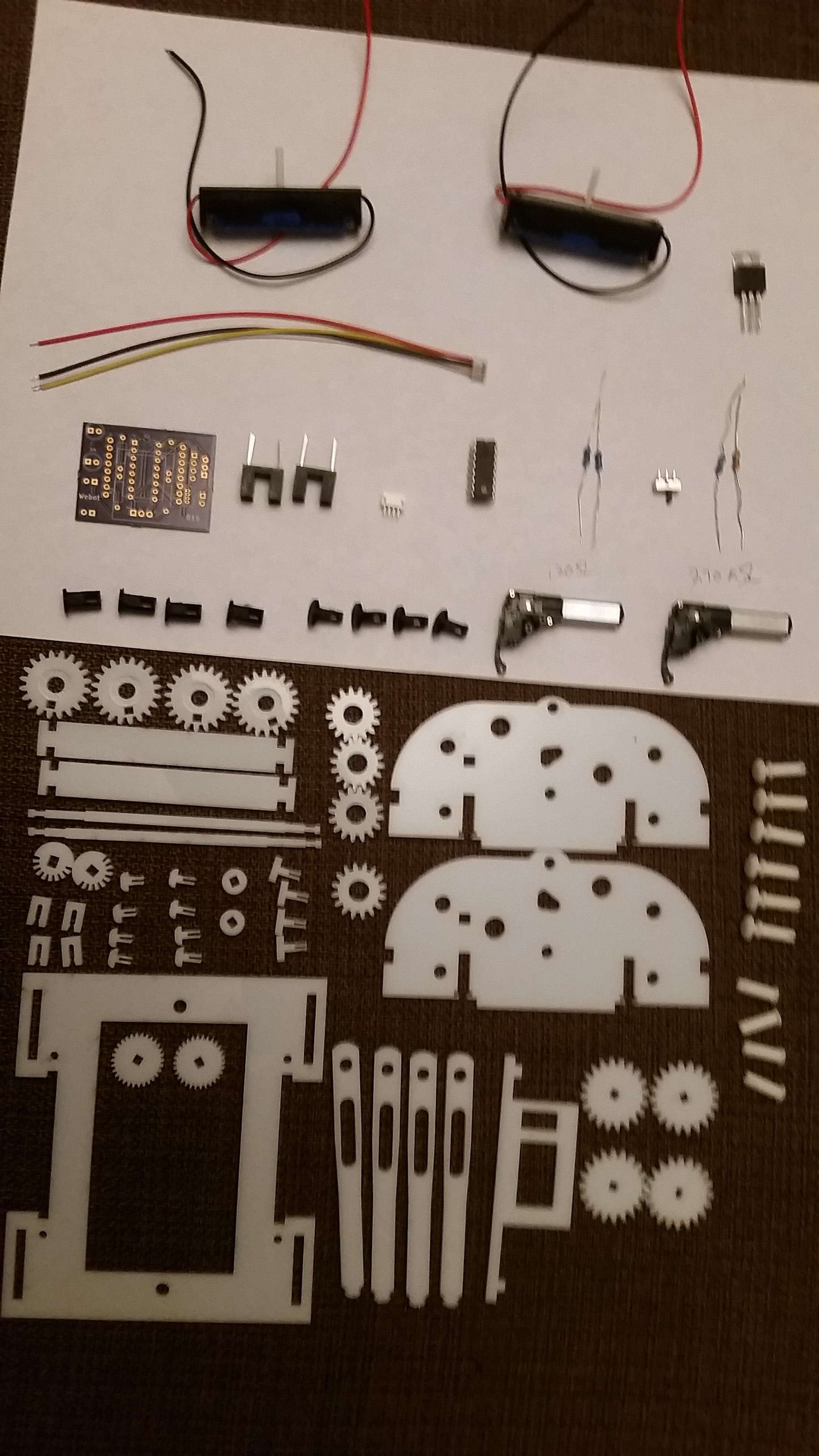
Today I will laser cut the 2.7mm acrylic I buy at Menards and see if I can get some nice friction free walking. I have the new Li Ion batteries. (10440 x2) and the new board that will work with the higher voltage from these batteries is being fabbed at OSHPark.
Here is what the layout looks like. Some how it is much sharper in real life.
-
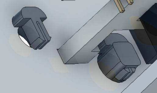
Fasteners
01/15/2019 at 04:25 • 0 commentsI had planned to use Chicago screws or book binding rivets. However, not only are they an additional cost and a impediment for someone to reproduce my work, the were binding when it was walking. The Chicago screws would come unscrewed and crash into the leg. Although I liked the feature that the robot could be disassembled, the has got to be a better way.
So after a few days of head scratching, I came up with a 3D printed and laser cut hybrid. First of all, this is more square pegs in round holes to try to reduce the points of friction. This robot does not go fast enough to worry about friction welding but the motors do not have enough juice to overcome a lot of friction.
The second feature is the super low profile and simple to print shape. There is a bit of bridging but I think the Prusa will print it like a charm. I went line to line on the vertical walls and gave it and extra 0.3mm on the overhang length. Lets see if my estimation is good.
The other great thing is that this removes 4 of the 8 counterbores from the laser. It will speed up the cut by a few minutes because it takes a long time to scan. I hand added the counterbores to adjust to a specific rivet width.
Here are some pictures.
-
Fusion and Non-Native Geometry
01/13/2019 at 15:11 • 0 commentsI am new to Fusion 360. I started working with it 45 days ago. However, I am blown away buy the ability to work with non-native files like step files. On Solidworks or Onshape, at Step file is just a piece of material. It does not recognize any features so you do not have much flexibility.
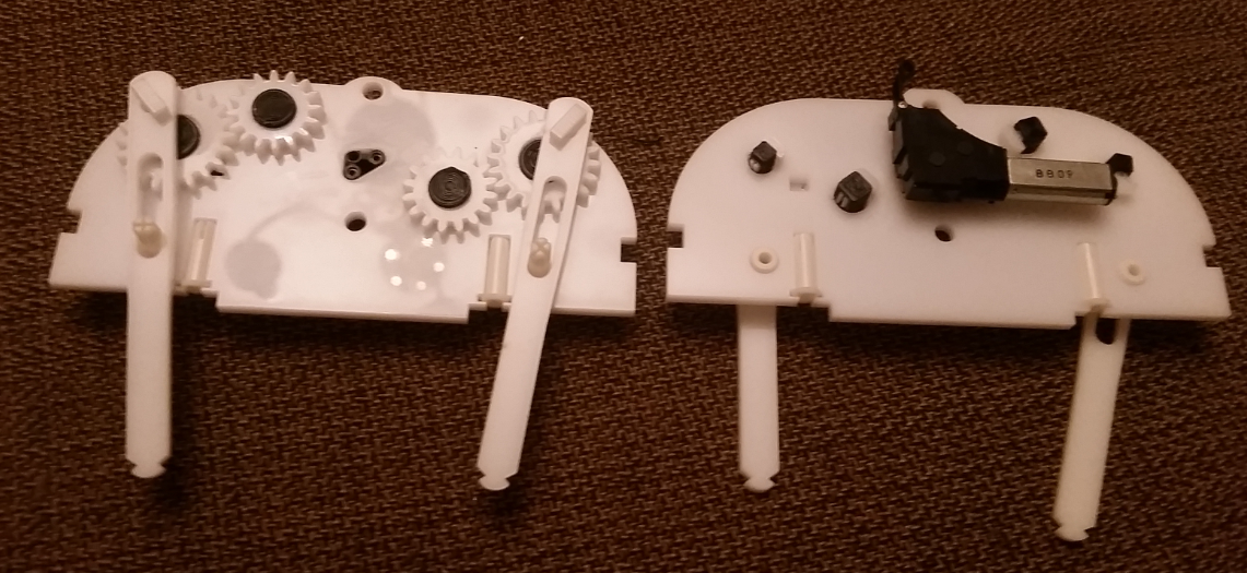
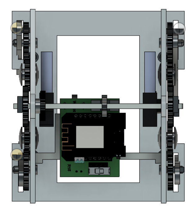
With Fusion, you can click on a hole and delete it. You can click on surface and type Q for push pull and you can move it around. Thanks to this flexibility, I already have my PCB mounted and the pcb mount reworked. Thanks to KiCad spitting out the the file, I know exactly where it is rather about where it might be. Here is the top view.
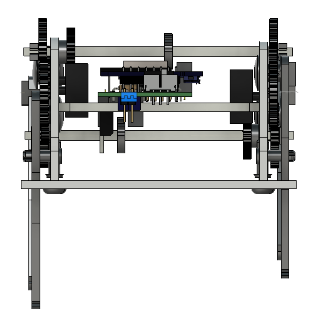
And from the back.
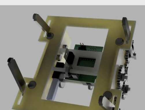
From the bottom.
-
CAD to do list
01/13/2019 at 12:16 • 0 commentsI have moved from Solidworks to Onshape and now to Fusion 360. I am struggling greatly with the pin and slot joint in Fusion even though I got it to work in Onshape and Solidworks. It works sometimes with contact surfaces but then it breaks. In any case, here are updates need to do for version 15.
1) I added 2 10440 Li ion batteries. One on each end. Some fastening method for the battery holder needs to be developed.
2) I am not happy with the Chicago screws that hold on the gears and I want to design a 3D printed alternative. It will take $0.75 out and make the walking smoother if I do it right. I am thinking about a type of friction weld to hold the 3D printed rivets in place for the gear axles.
3) Solidworks has the concept of parts and I could change the parts and the separate assembly that is all ready for laser cutting changed as well. Fusion is not set up like this. I read that people make a separate components for laser cutting using the same sketches. That way they update automatically. This makes sense and I want to try it.
4) I need to hold the board in place better. Now that I have the 7805 dropping below the board have something to hold on to so I may be able to hold it in place so the encoders actually work.
-
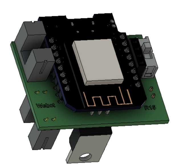
ECAD to Fusion 360
01/13/2019 at 11:30 • 0 commentsI have always kept my PCBs and electrical parts separate from my models. With KiCAD I learned how to output the 3D board with any components that were in the system. The output is an easily editable step file and I can add the component that were not in the library in Fusion 360. Here is a picture of my new board.
-
Battery Power 2
01/12/2019 at 12:00 • 0 commentsToday ordered 4 AAA Li Ion batteries and a charger from Amazon.
https://www.amazon.com/gp/product/B06X9TZ1CG/ref=ppx_yo_dt_b_asin_title_o00__o00_s00?ie=UTF8&psc=1
I also bought some single battery holders.
https://www.amazon.com/gp/product/B07C2XT5C5/ref=ppx_yo_dt_b_asin_title_o00__o00_s00?ie=UTF8&psc=1
By distributing the weight front and back, the balance will improve and the robot will not fall over while taking a step.
By using the 2 Li Ion I will get 2 benefits. Reduced weight over 4 regular or NiMH batteries and the combined higher voltage will give me more speed for my motors.
The down side is I will have to modify my circuit to add a 7805 voltage regulator. Maybe I can use the 7805 part as a battery stop hanging below my board.
In my circuit, to make the motors go faster, more than 5V is helpful. 7-8 V might be idea. However, the Wemos can only handle around 6 V before letting out its magic smoke. I have a diode in the circuit now to reduce the voltage by 0.6V but I think I will replace the diode with the 7805 voltage regulator to allow the 2 Li ion batteries to be used at their full charge of 8.4V to their depletion charge of about 6V.