 Mime Industries
-
1Step 1
You can also check out a video of the build
-
2Step 2
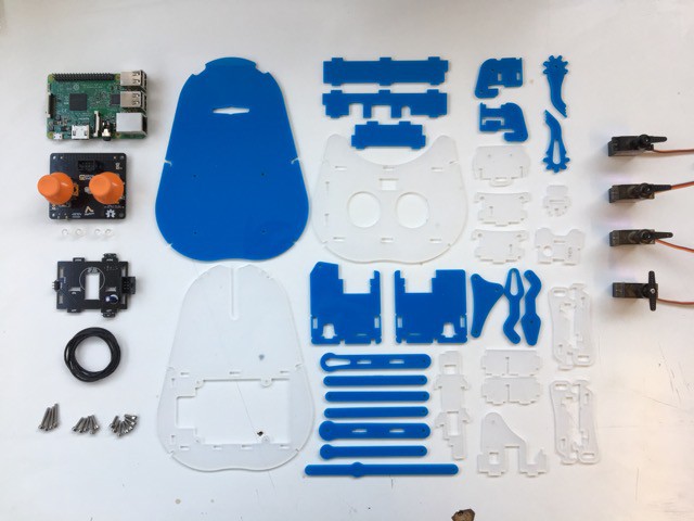
Cut the mechanicals - use the DXF file in the files section to cut out the different parts from 3mm perspex
![]()
-
3Step 3
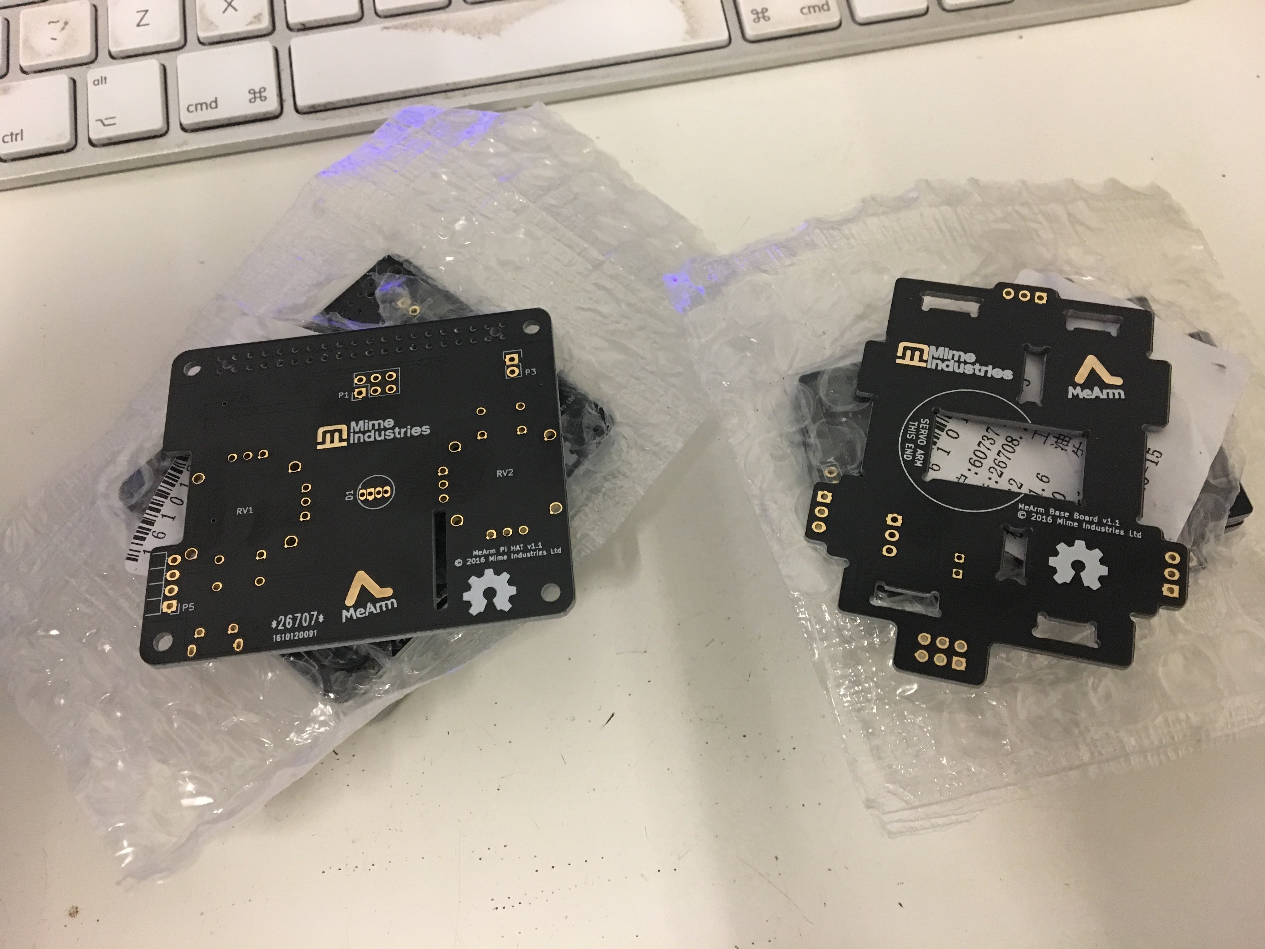
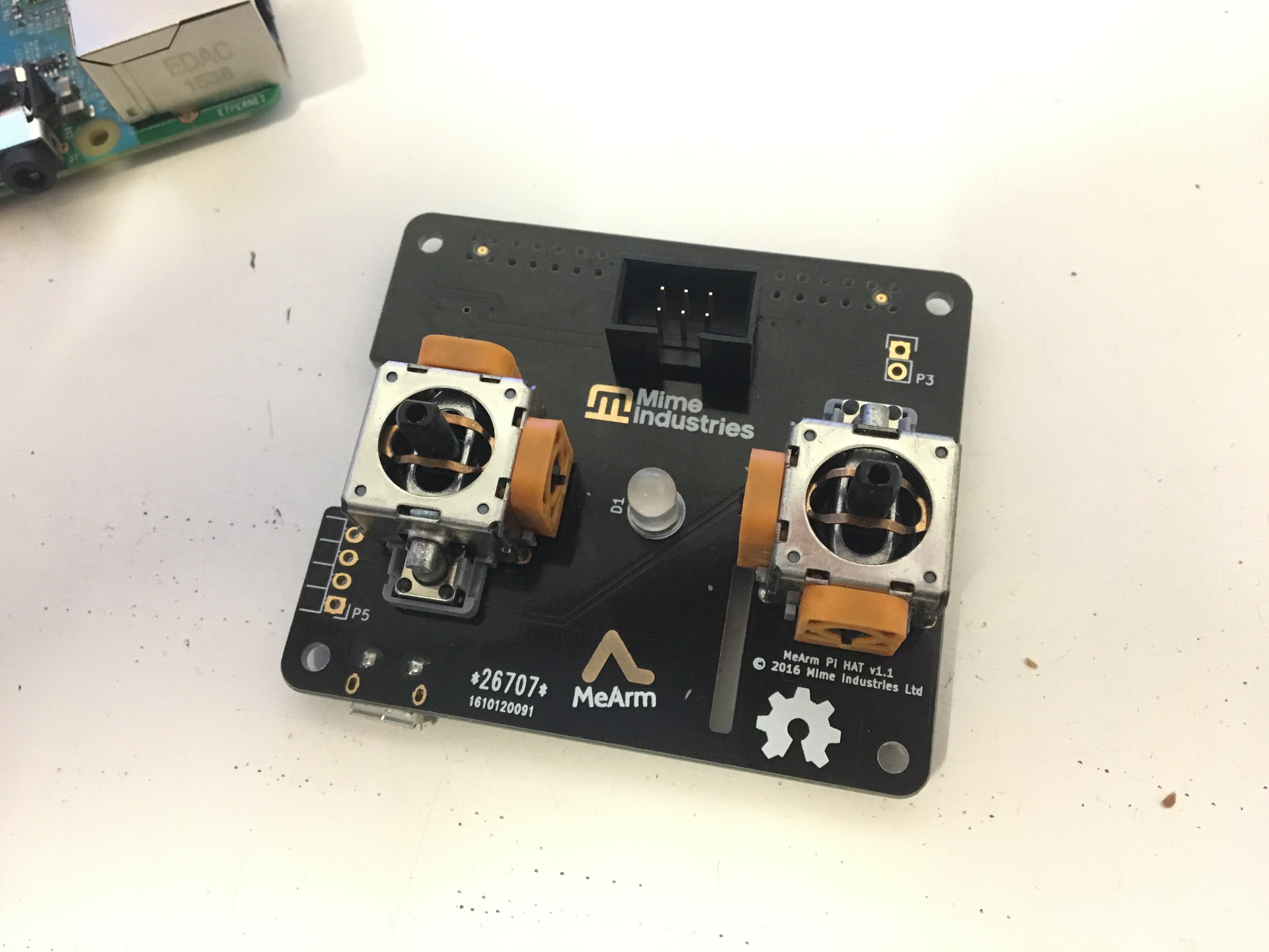
Make the PCBs.
![]()
I tend to use Dirty PCBs for this. You'll need to use the production files in the GitHub releases for each board to get these made. Once you've got them back from the PCB manufacturer you'll need to solder all of the components in place. There aren't too many of these and whilst some are surface mount they aren't too bad to do by hand.
![]()
-
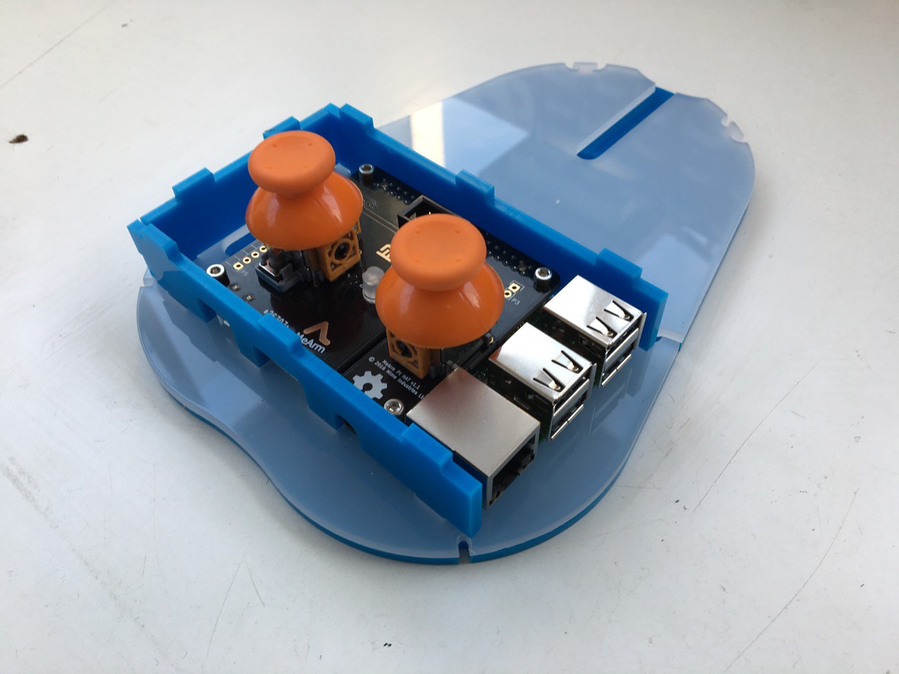
4Step 4
![]()
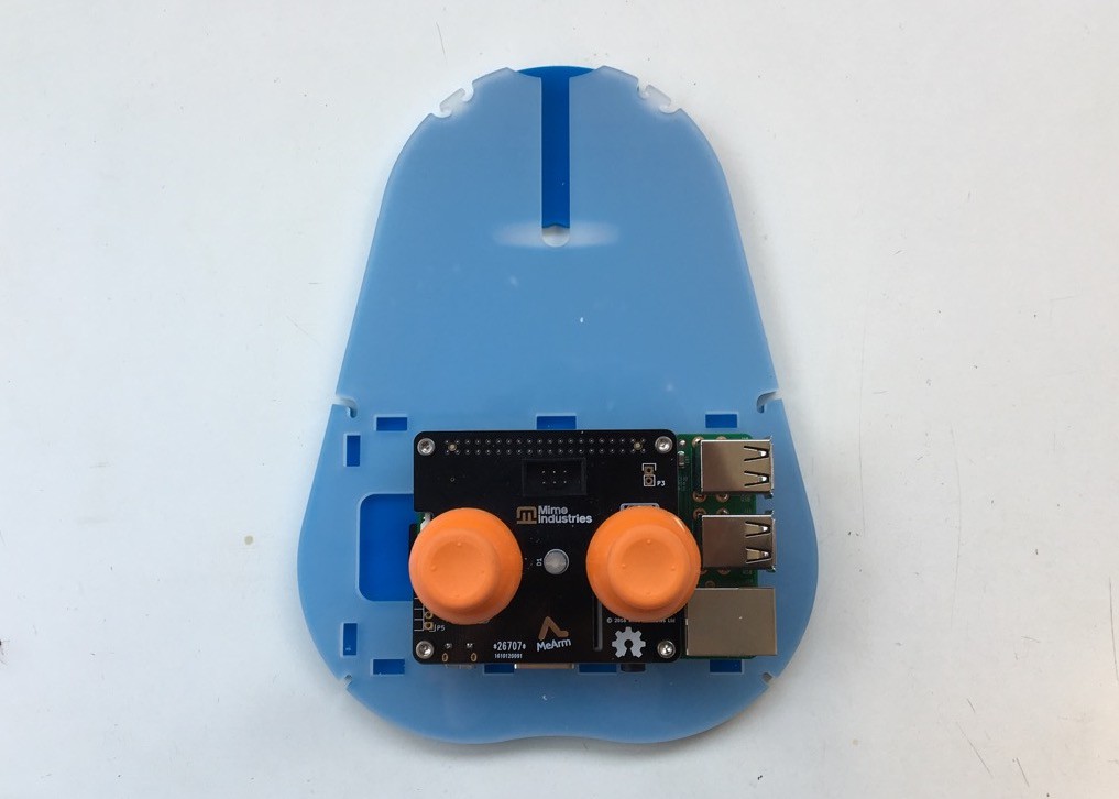
Put the two halves of the base together then screw the Raspberry Pi (with the HAT on) in to place using the M2.5 screws so that the two halves are held together with the spacers inbetween
-
5Step 5
Put the sides on to the Pi base as shown
![]()
-
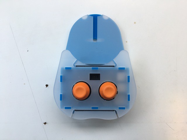
6Step 6
And finally put the top on and hook it in place with the elastic bands. You can also add the joystick covers (I couldn't find my matching blue ones!).
![]()
Once you've done this part you can put this to one side for later.
-
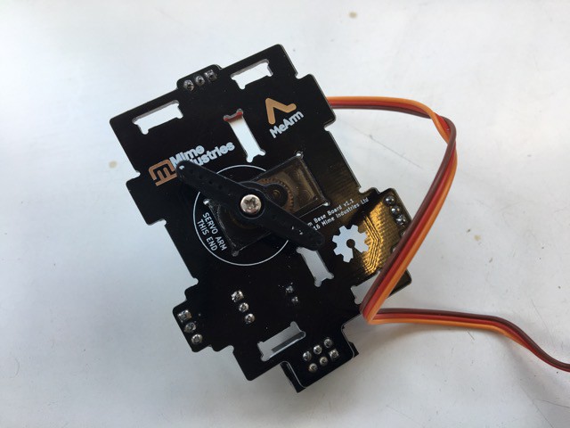
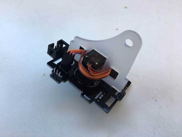
7Step 7
Slot the servo with a double-ended horn in place in the base PCB as shown. Make sure it's the right way round by aligning the horn with the circle.
![]()
-
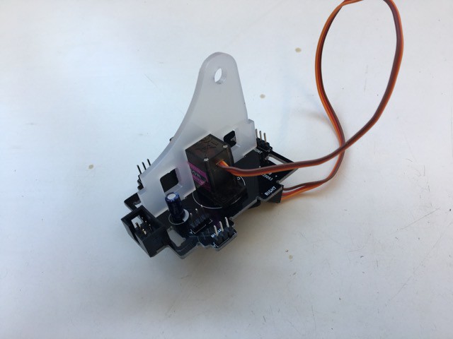
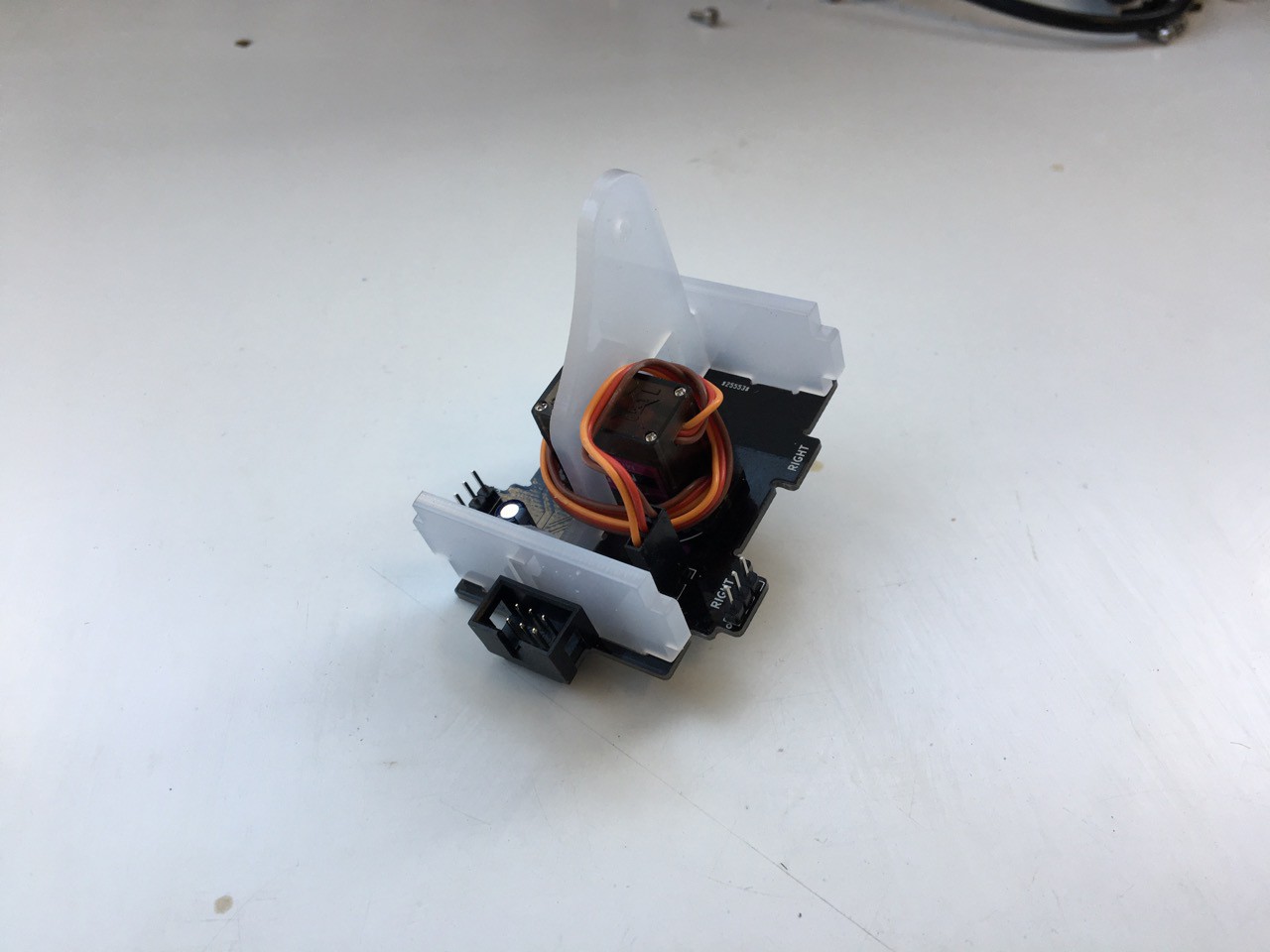
8Step 8
Slot the centre piece over the servo to hold it in place. It will only go one way round.
![]()
Then wind the cable around through the two holes to keep it tidy (we like tidy cables)
![]()
-
9Step 9
Put the two end pieces on as shown in the photo. Again, they will only go on one way round
![]()
-
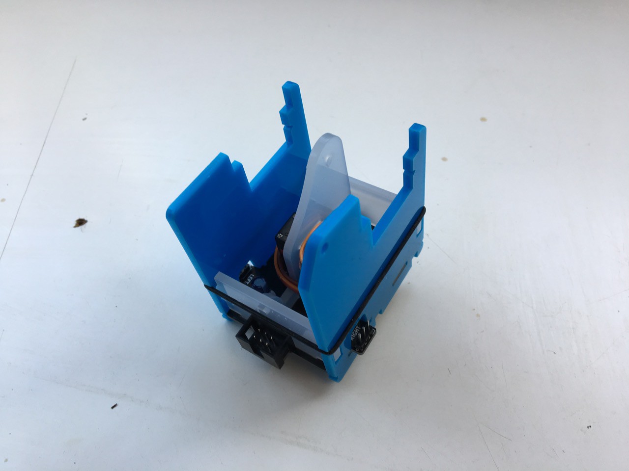
10Step 10
Put the two side pieces on (they'll only go on the right way - stuck record!) and then put an elastic band around them to hold them in place while you're working with them
![]()
MeArm Raspberry Pi Edition
A robot arm kit that works with the Raspberry Pi
Discussions
Become a Hackaday.io Member
Create an account to leave a comment. Already have an account? Log In.