A gif is worth more than 1000 words:
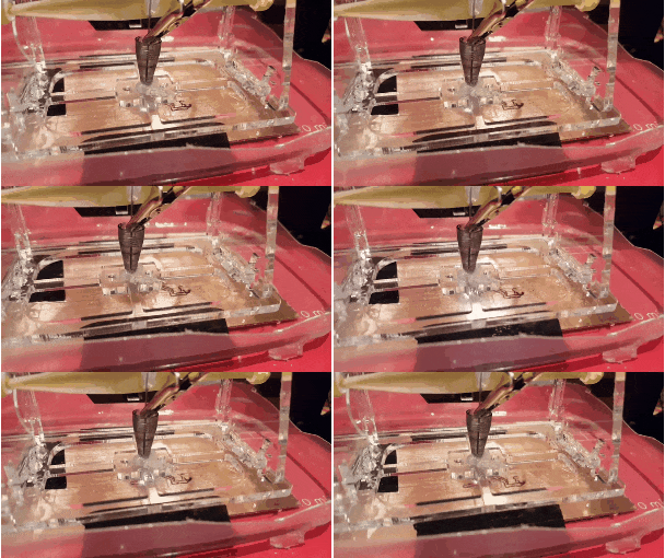
Like you, we dream of being able to make PCBs fast, since it is 100% impossible to get it right the first time. We've done etching, but got low yield and the chemicals are kind of nasty. Milling is slow, and requires expensive hardware. The tiny mill tooling needed are brittle and require slow movements so they don't break. The electrodes used here do not need to support basically any loading, so you can cut faster, holding the workpiece is easier (we used tape), the machine structure itself does not need to be very stiff, and we can use really thin electrodes. In addition, pencil lead is a whole lot cheaper than mill tooling. There is also no worry about fiberglass dust from milling FR4. We think this idea has promise, but there's a ways to go still.
We've learned a few major things about trying to do this:
- Of all materials we tried, graphite electrodes worked best. Metals will tend to weld to the PCB, as you might expect.
- Between 30-60V is sufficient for cutting, so you can use your power supply easily.
- There needs to be a light touch between the PCB and the electrode for the cutting to succeed. If you push too hard, it just shorts and won't cut. By hand it is easy to get the pressure right, but with CNC it is much harder.
- Pencil lead from 0.4-0.8mm all seem to work fine.
- Cutting underwater (distilled ideally, although our tap water was non-conductive enough) cleans up the cut drastically. Distilled water or oil is typically used in industrial EDM and serves as a dieletric which helps control the spark and helps clear away the EDM chips.
There are some hard problems to solve before this is useful:
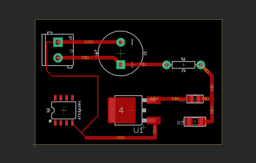
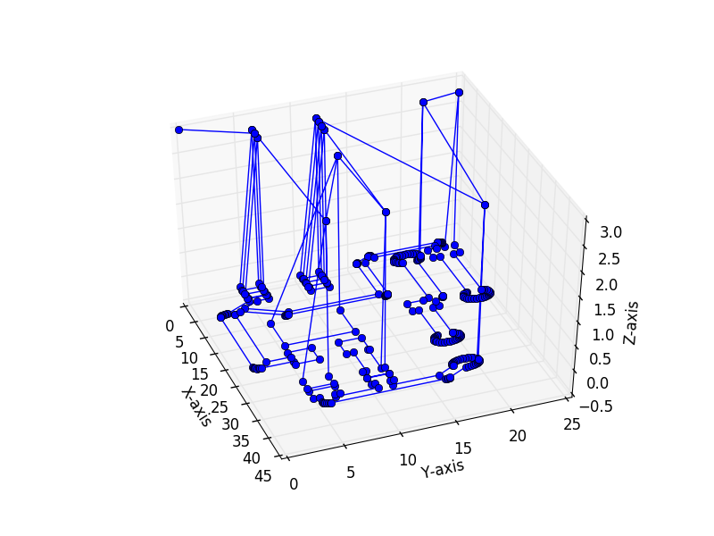
- Need to be able to create the tool-path to cut from the gerber files. There are open source tools for doing this for milling, and the problem here is close. However, with this setup a circuit must be maintained, so if you were to cut a full loop and then try to cut inside of that, it would not work. Therefore we either need:
- Tool-path generation that accounts for the need for continuity throughout the process. This may be theoretically impossible, or NP hard, we don't know.
- Raster across and cut from one side to the other. This probably would produce lower quality cuts, but we haven't tried it.
- Have the negative electrode able to move and somehow guarantee continuity.
- PCB blanks (at least the cheap ones we used) aren't very flat. Combined with the consumption of the graphite, the motion needs some closed loop control to ensure cutting continues. Could also use this control to ensure a "light contact" to the PCB.
There are also some things to be aware of and careful about:
- There is clearly electrolysis between the electrodes in water. The O2 and H2 productions are too small to matter in a ventilated area, but don't try this enclosed.
- The sparks are VERY bright and should not be looked at without eye protection. It should probably be treated like welding from a vision protection point of view.
- The continuous sparking are spewing EM radiation, so probably should be shielded to not potentially interfere with other things.
- This is relatively high voltage and power (and very high heat at the electrode), so don't try this unless you know what you are doing.
Note: it looks like another Hackaday member was working on this idea years ago but seems to have stopped working on it, and it's not clear how far he got.
Project Logs:
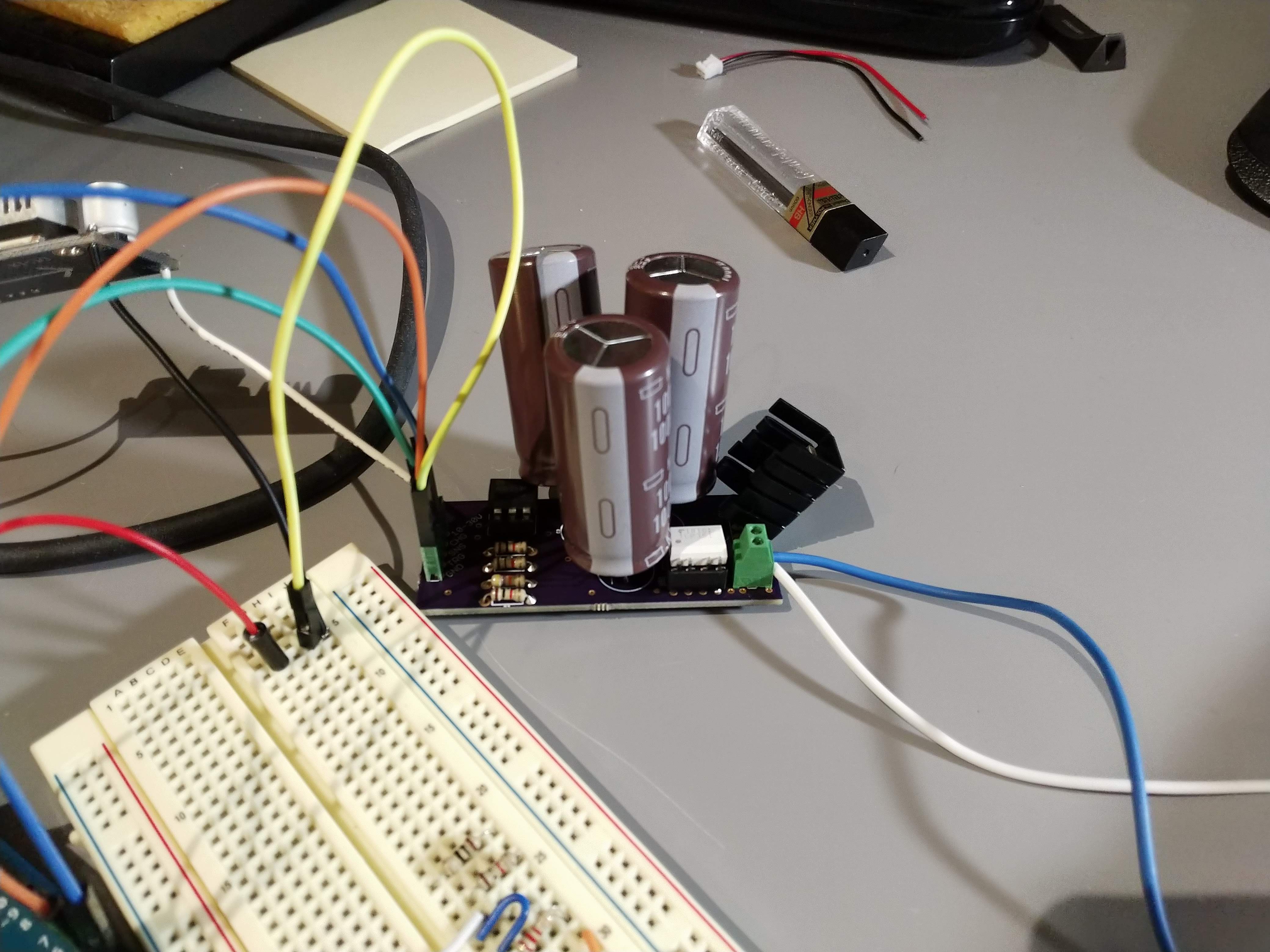
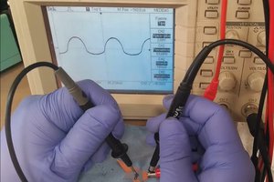
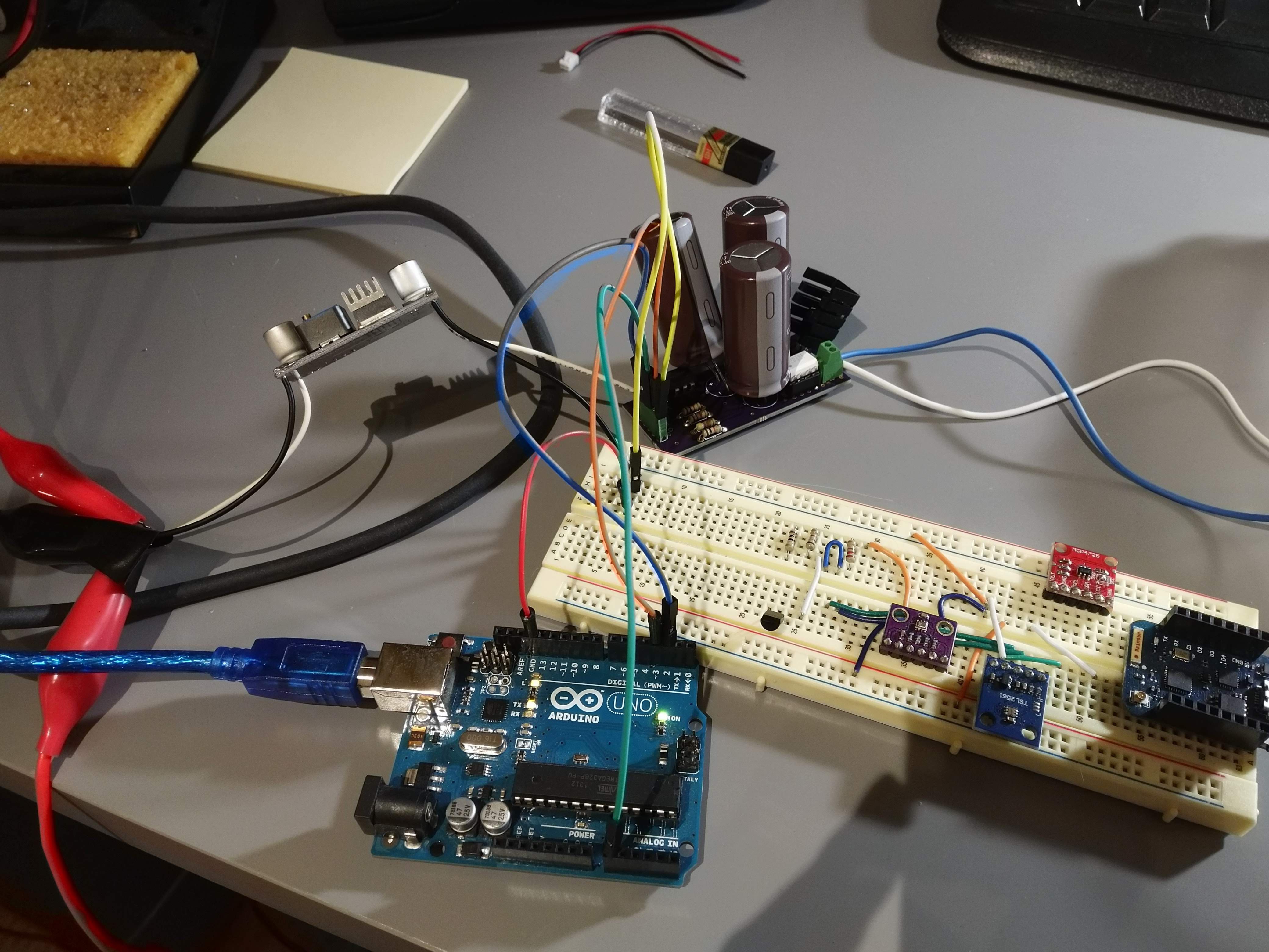 Even my prototype shows why I need this system. I somehow messed up sizing the capacitors and bought much too large versions. Each capacitor is 1mF, 100V rated. All in parallel there is a total of 3mF. I used three in parallel to lower the overall ESR so they can discharge fast. I charged them up to 37V with the boost converter. The Uno first charges up the capacitors until they reach some voltage. Then, it disconnects the charging circuit and switches the mosfet to discharge the capacitors. The average power needed by this system is not very high (seems <3W), but peak power is high. By alternating, the hope is this will shift the peak power handling to the power MOSFET and capacitors that can handle it, and away from the power supply.
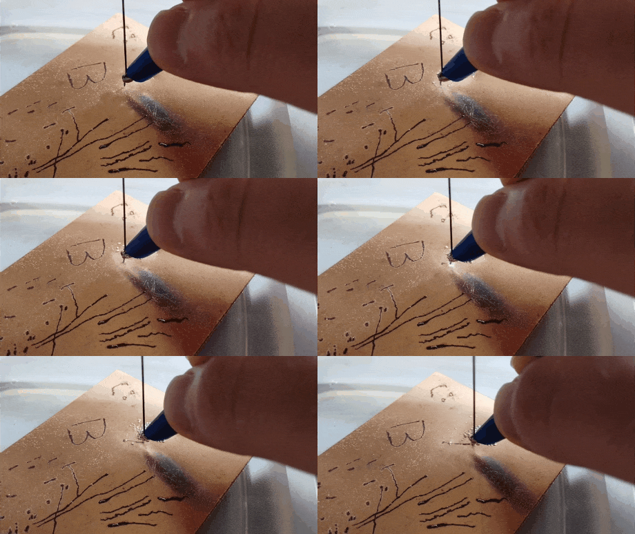
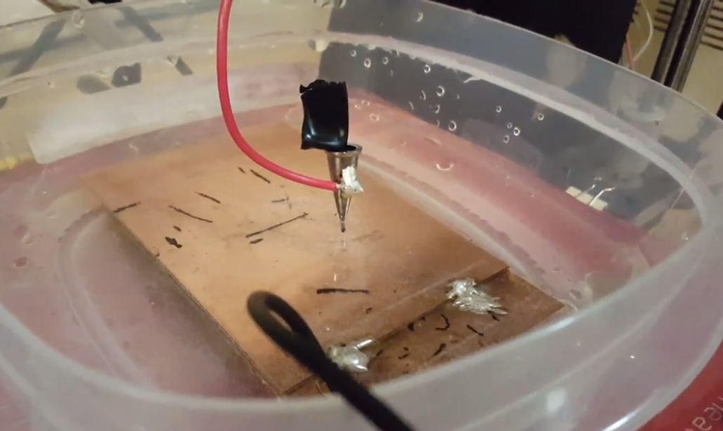
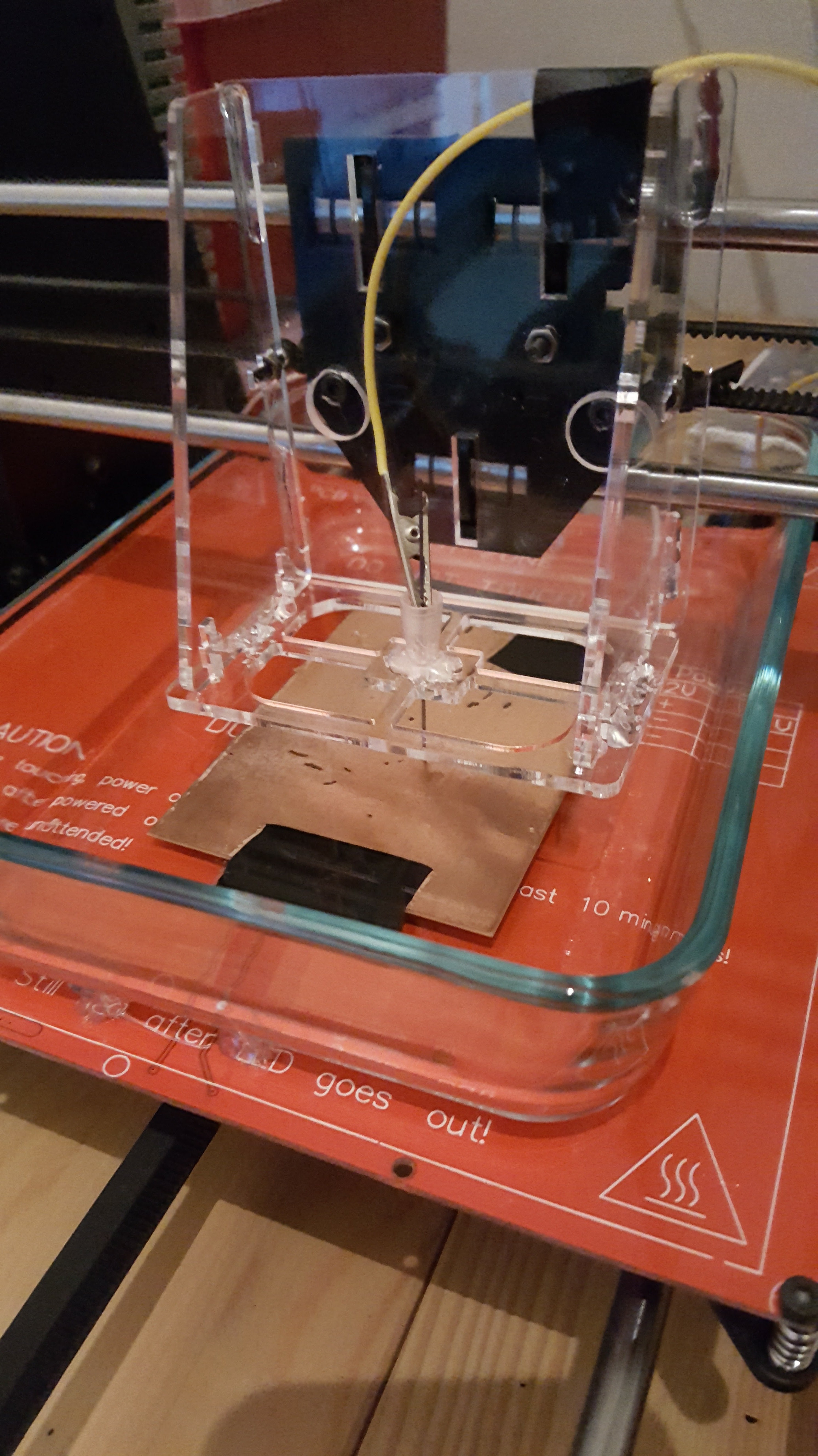
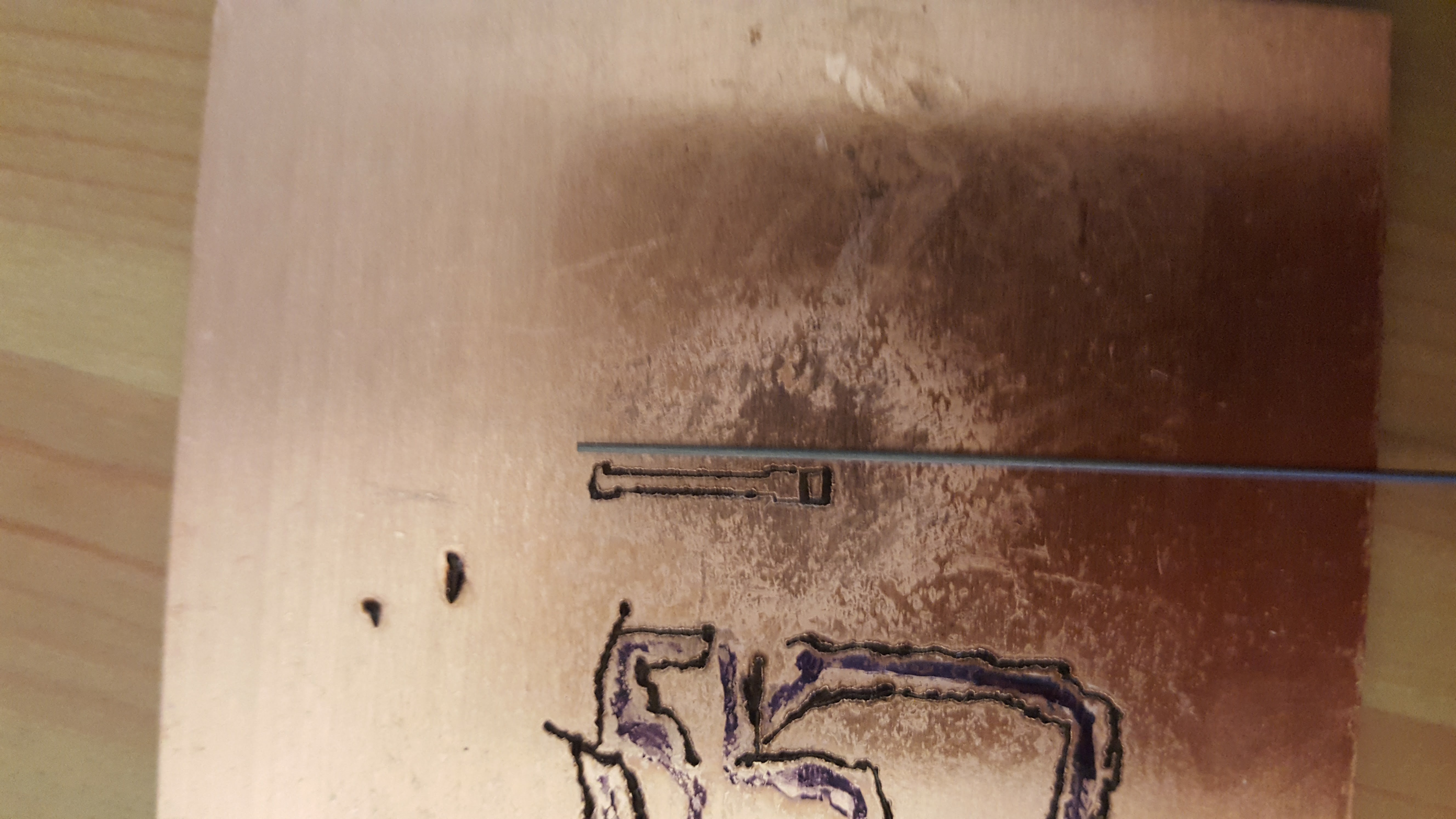 Finally, some video of the cutting process. The cutting is pretty fast, but obviously there are sections where it pulls away from contact and stops cutting.







 CriptasticHacker
 mosaicmerc
 Bob Baddeley
 Nixie
Nixie
Love this project the implications can be fantastic for at home pcb manufacturing. If the substrate material was say aluminum it could do holes and vias with the same setup.