Close
0%
0%

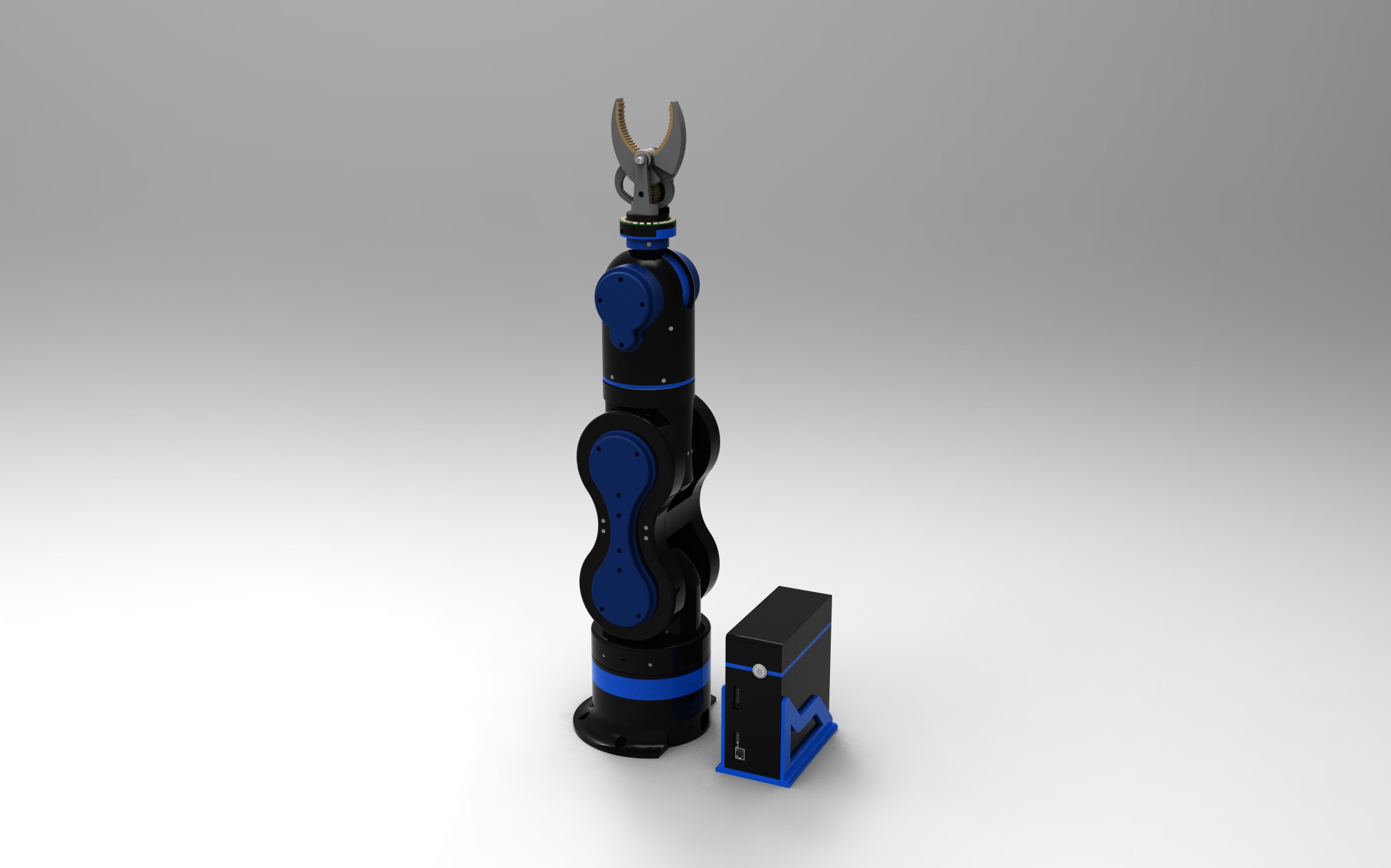
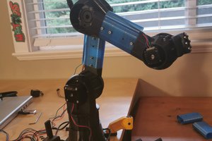
'Thor' robot with addons and GUI

Thor robot based on the author AngelLM

Similar projects worth following
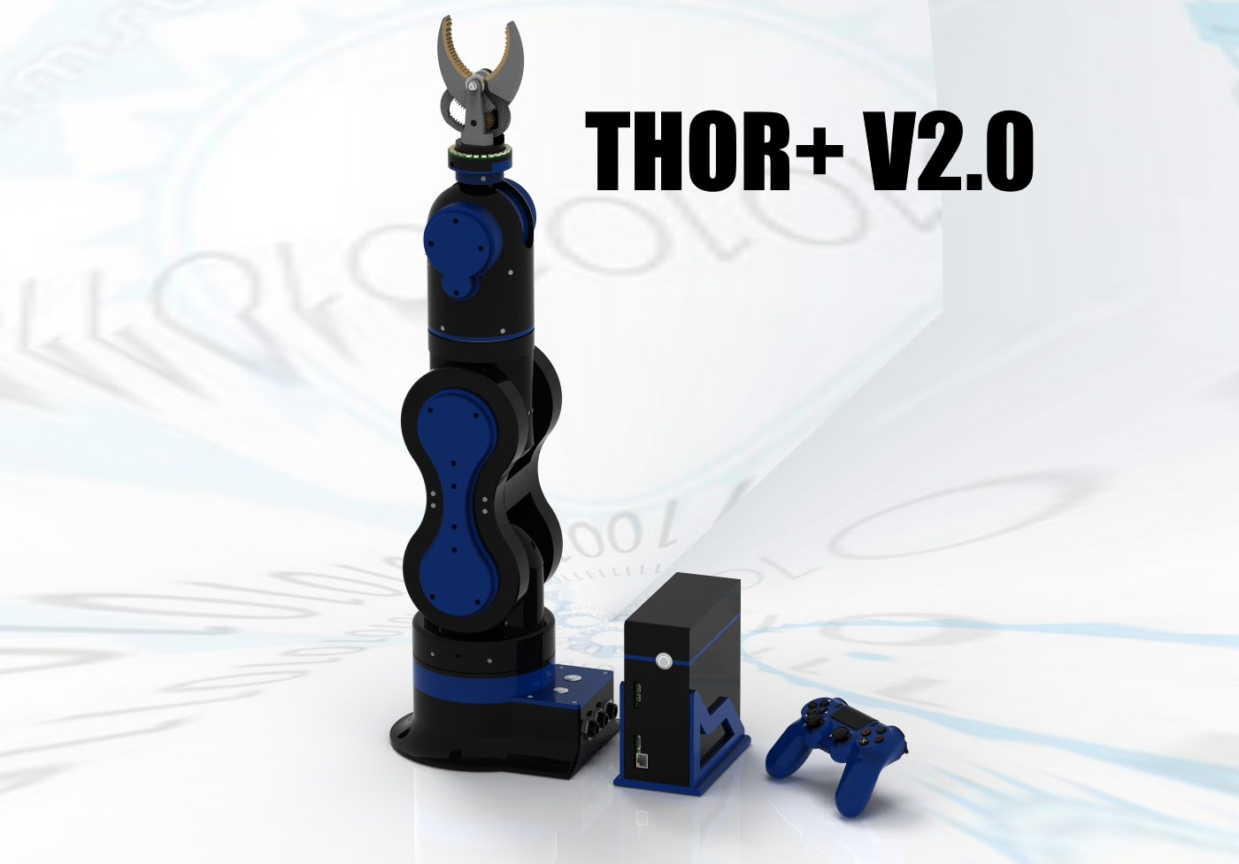
THOR robotic arm with some extra's :) based from the original design of AngelLM, thanks mate for this nice piece of work!
Trying to do something more... follow me to see the addon's and lots of improvements.

This project is based on the THOR robotic arm project from AngelLM and will be a version with lots of add-ons and especially modified for a wide range of 3D printers with a smaller print area.
Also it is my intention to improve a lot of things to the robot his hardware and software.

I am working on a graphical controller that works on PC,MAC and later on mobile devices.
You will have the possiblity to make al the movements on the controller without the need of the robot.
Ones everything is working on the GUI controller it can be transfered to the robot arduino controller
board, with the press of a button and some digital inputs you can run the sequences you programmed in the GUI controller.
There will be a hand controller to move the robot manually and store the points, afterwards you can send these points to the graphical controller. It will be bi-directional programming.
In a further stage the axis will be recorded into the controler so movements can be simulated be moving the robot by hand and can be replayed afterwards.
It's a lot but this will be my challange in the next comming days...months :-)

Any feedback is welcome!

I will send my regards to AngelLM for the original nice designed robot called 'THOR' , without him I could not started this SUPER project!

Everything stays open source, like everything should be...One for All, All for One
All software programs to build the robot are free to download

STL_V2.04.rar

Upgrade STL parts from V2.03 to V2.04 Overall stability feedback add-ons, extra fans added and design improvements.

RAR Archive - 3.17 MB - 09/24/2017 at 08:27

Download

ROBOT_THOR_V2.04.rar

Step design Thor+ V2.04

RAR Archive - 10.31 MB - 09/24/2017 at 08:26

Download

STL_V2.03_BASE-VERTICAL-HOLES.rar

Base with fan and vertical hols Thor+ V2.03

RAR Archive - 292.74 kB - 09/02/2017 at 00:05

Download

THORV2_03.rar

Step design file Thor+ V2.03

RAR Archive - 10.26 MB - 08/29/2017 at 05:48

Download

STL_V2.02.zip

THOR+ V2.02 All STL Files Feedback sensors add-on

Zip Archive - 40.59 MB - 08/05/2017 at 20:39

Download

View all 22 files

  • 1 × 3D printer to print the parts UPrint SE plus Stratasys
  • 1 × GUI software controller Unity personal
  • 1 × Ultratronics V1.0 Pro main board The main controller for the robot
  • 1 × Arduino mini board The controller inside the robot Art2 to control IO/Gripper/Leds/Feedback sensors, etc...
  • 1 × Programming software arduino arduino plugin + visual studio community 2015

View all 6 components

  • UPGRADE THOR+ V2.04

    dannyvandenheuvel09/23/2017 at 20:27 7 comments

    Upgrade Thor+ V2.04 ... Feedback stability improvements, Added extra fans and changed some design. (By Sepio & Danny)

    All STL and STEP files online!

  • VENTILATED BASE

    dannyvandenheuvel08/15/2017 at 13:28 6 comments

    Add some cooling ribs in the base and added fan 40x40x10 inside

  • THOR+ V2.02 WITH FEEDBACK SENSORS!

    dannyvandenheuvel08/05/2017 at 21:07 11 comments

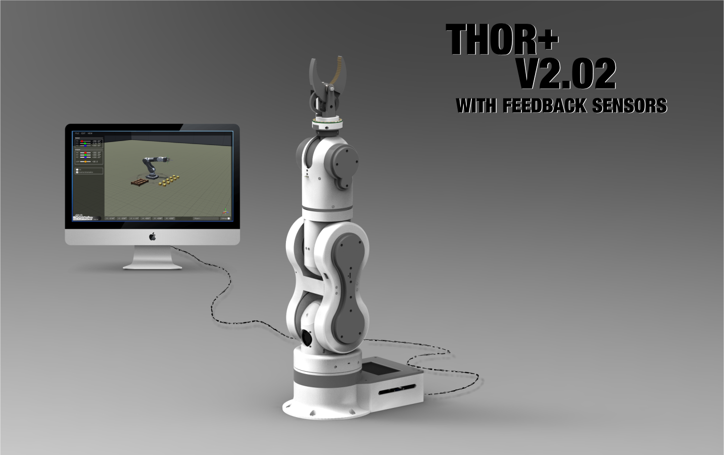
    Finally! It's here, Thor+ V2.02 with integrated feedback sensors :-)

    STL files all online.
    For users how have printed V2.01 all files marked with a leading underscore are new or changed in V2.02.

    Happy printing!
    Thor+ V2.02 is based from the original idea & design of AngelLM

    The difficult part in assembling the robot parts will be the feedback sensor joints, be carefully how they have to rotate around there axis. I will make a manual later on. All the rest is very clear the same as AngelLM his version.


  • Robo GUI controler 'Progress status 07-2017'

    dannyvandenheuvel07/07/2017 at 21:18 3 comments

    I wasn't prepared enough, so sorry for my bad english :-( , I hope you understand it a little bit, anyway it's funny...

  • UPDATE THOR+ ROBOT_GUI CONTROLLER

    dannyvandenheuvel04/30/2017 at 12:54 3 comments

    Now loading and saving opportunities. Playing has been more fun now because we can save and load! Yeahhh.

    Now you can play with it! Next will be save and load senarios and connection with real robot arm through ethernet. Try to upload new version in a couple of days :)


    Some progress Thor robot arm embedded, almost running inverse kinematics routine :)

    At this moment I build a recorder into the Thor robot gui controller, following will be save and load recorded movements. Then TCP socket to communicate with the real robot arm! will be continued :) I used a other model to test the routine, it's temporary :). Thanks to Luca Filippini for helping me with the Inverse kinematics scripting!

  • UPCOMMING THOR+ V2.02 WILL HAVE ABSOLUTE FEEDBACK SENSORS ON ALL AXIS

    dannyvandenheuvel04/08/2017 at 14:44 6 comments

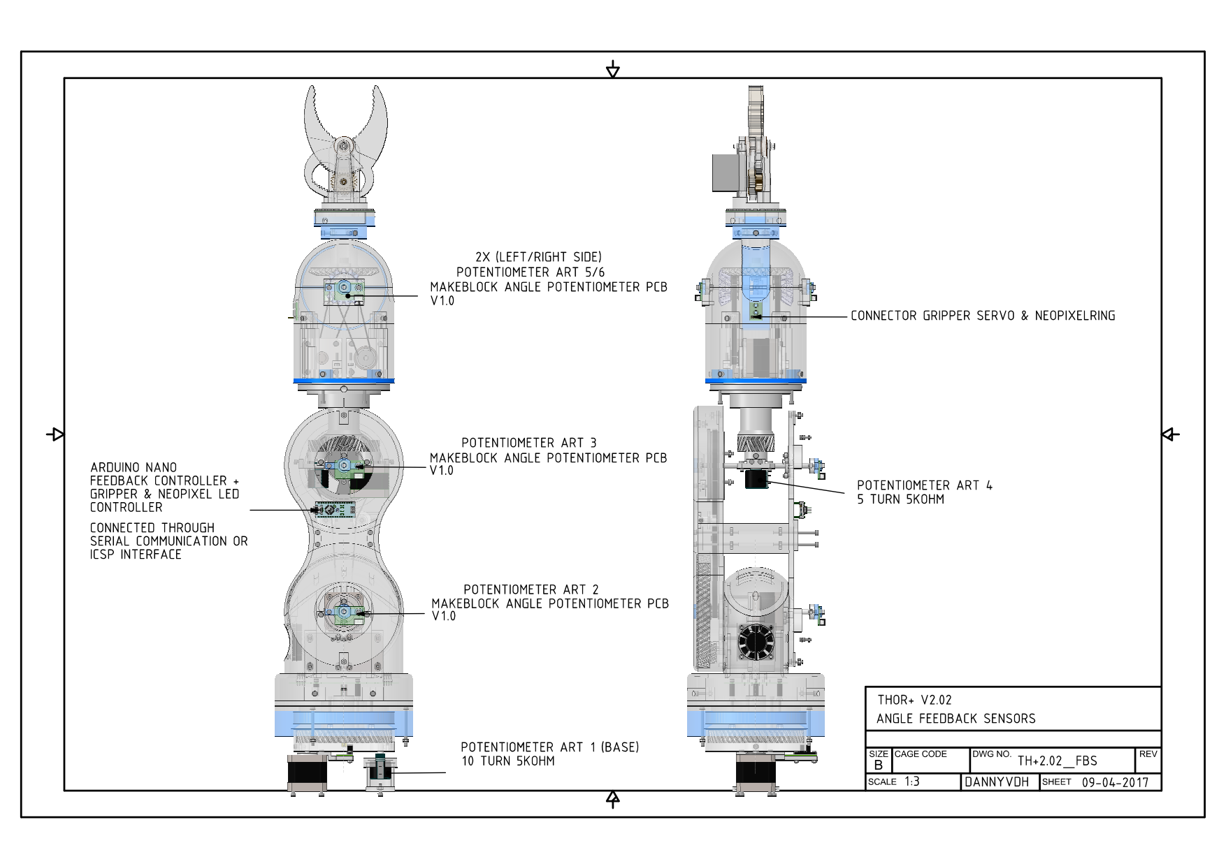
    Thor+ Feedback sensors for Art2 and Art3
    All feedback sensors, gripper servo and neo pixel ledring will be controlled by build-in arduino nano
    serial connected to the main controller board.

    Sheet all feedback sensors integrated into Thor+
    Sensors:
    4 x Makeblock Angular sensor V1.0
    1 x 10 turns potentiometer 5Kohm (burns)
    1 x 5 turns potentiometer 5Kohm (burns)

    Controller:
    1 x Arduino Nano controller

  • THOR+ V2.0 ALL STL PARTS ONLINE!!!

    dannyvandenheuvel03/30/2017 at 12:51 1 comment

    Good news! All stl parts online V2.0
    Start printing : - )

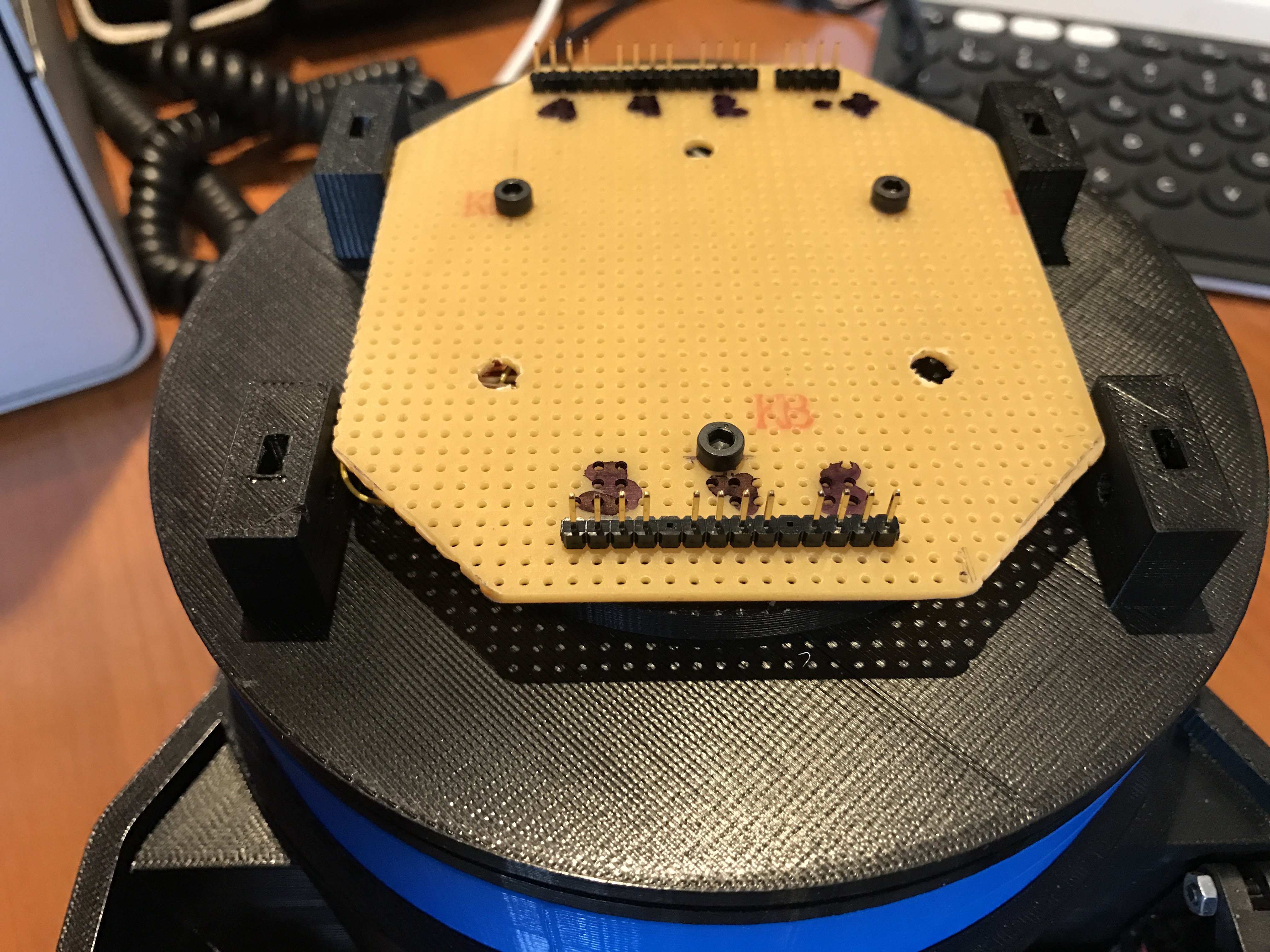
  • 'ADDING SLIPRING TO THOR+'

    dannyvandenheuvel02/19/2017 at 14:47 1 comment

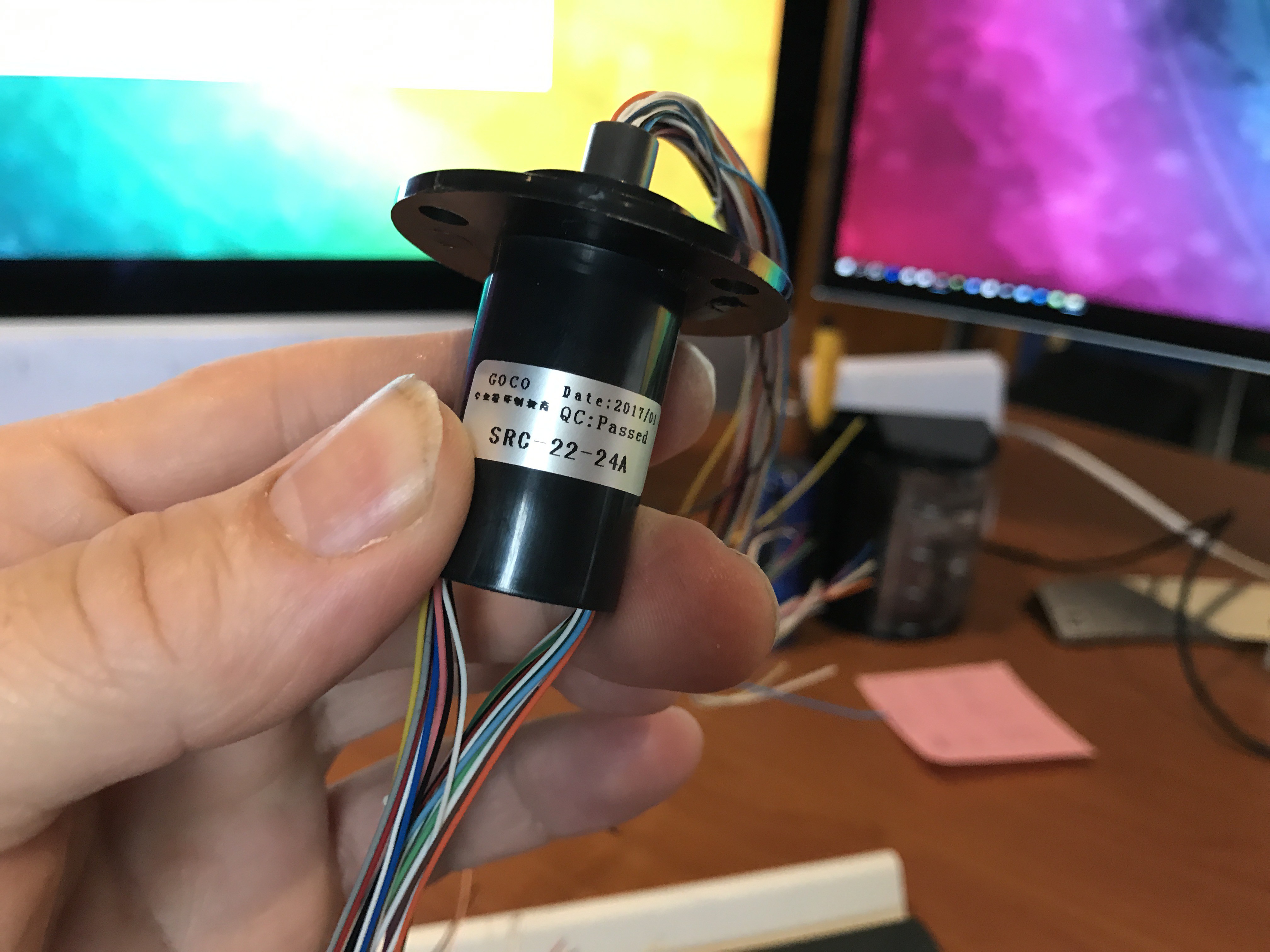
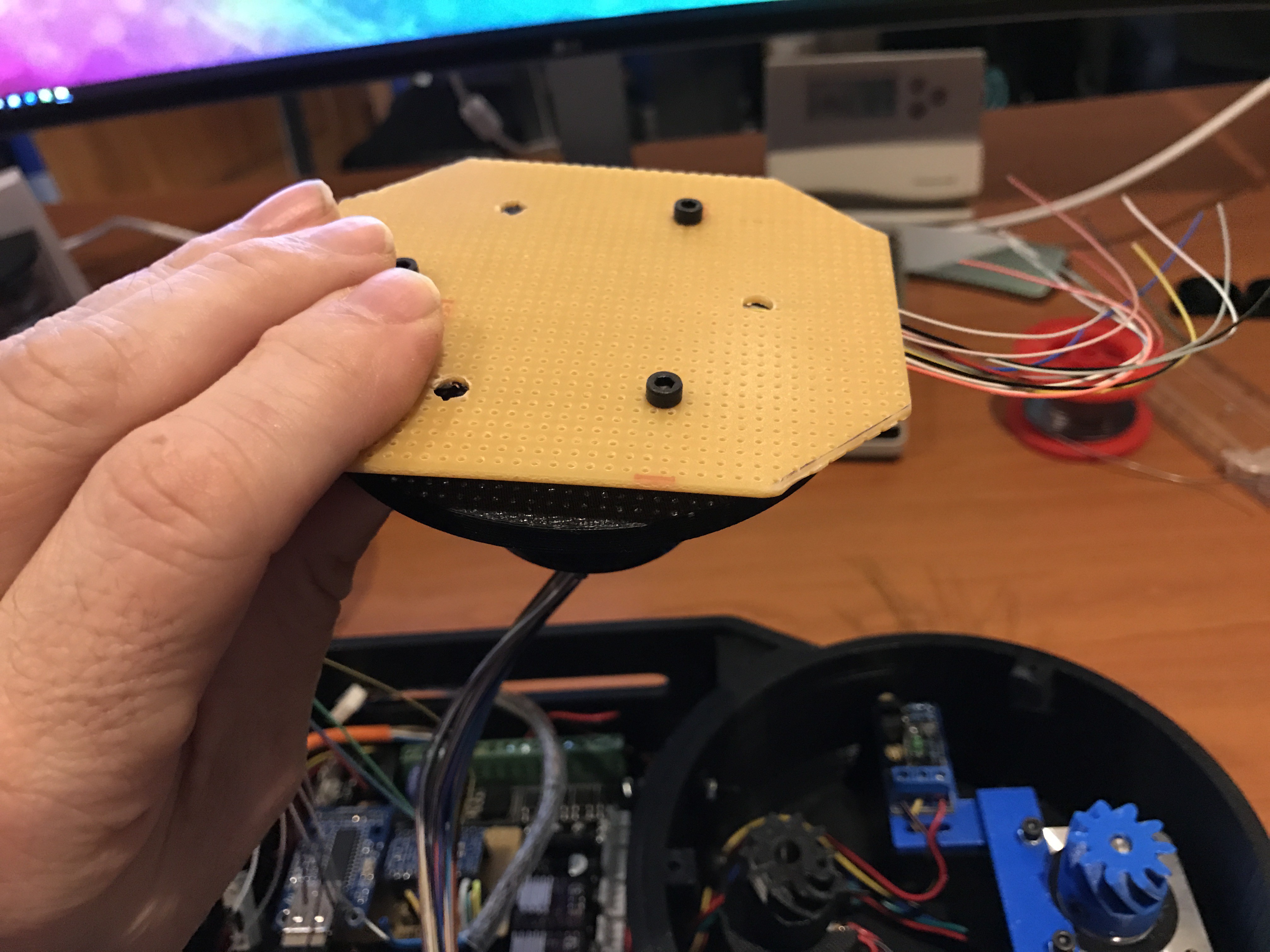
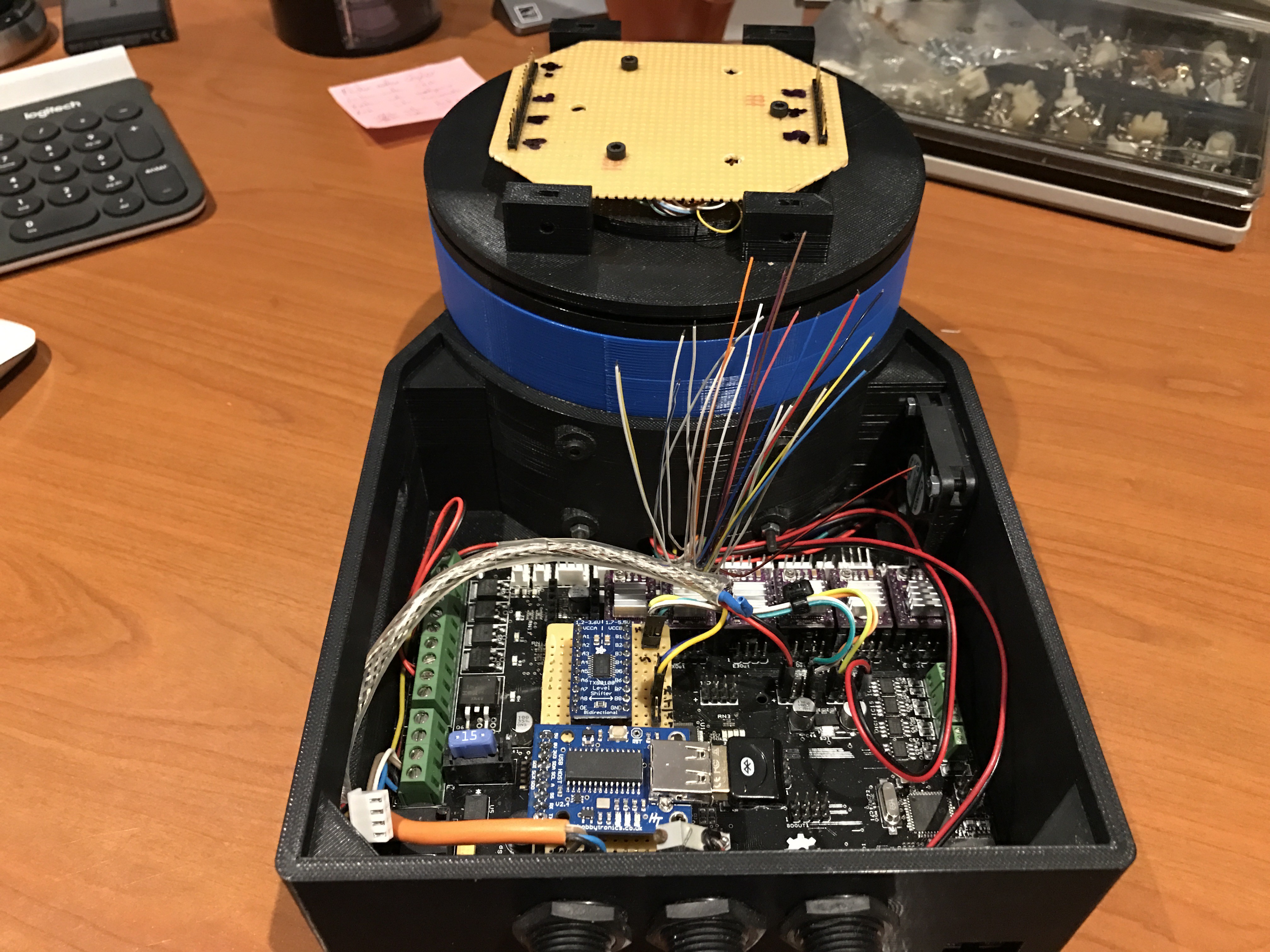
    Finally get my slipring from ebay! It's going to connect my 6 stepper motors and arduino mini.
    I didn't like the many wires hanging around.

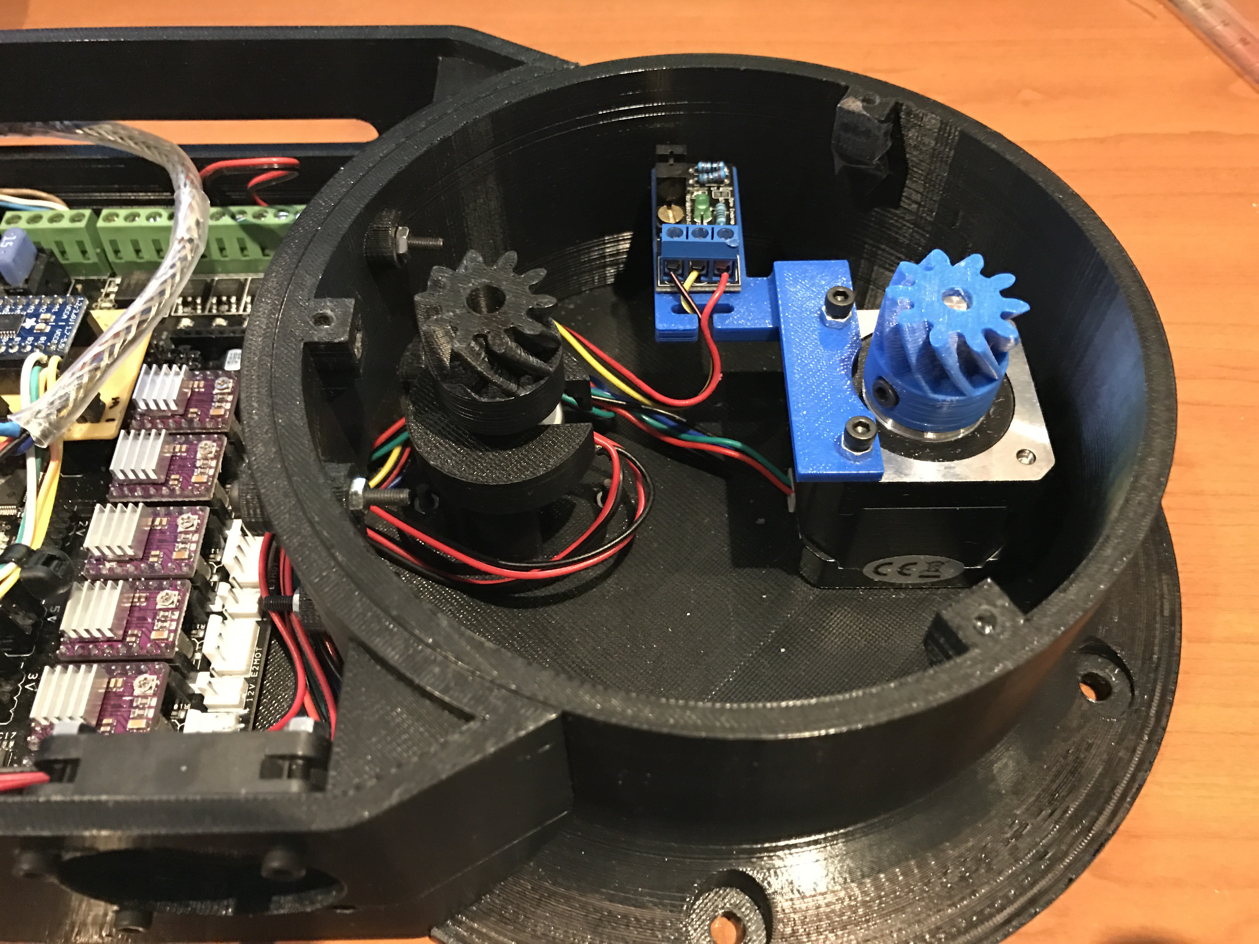
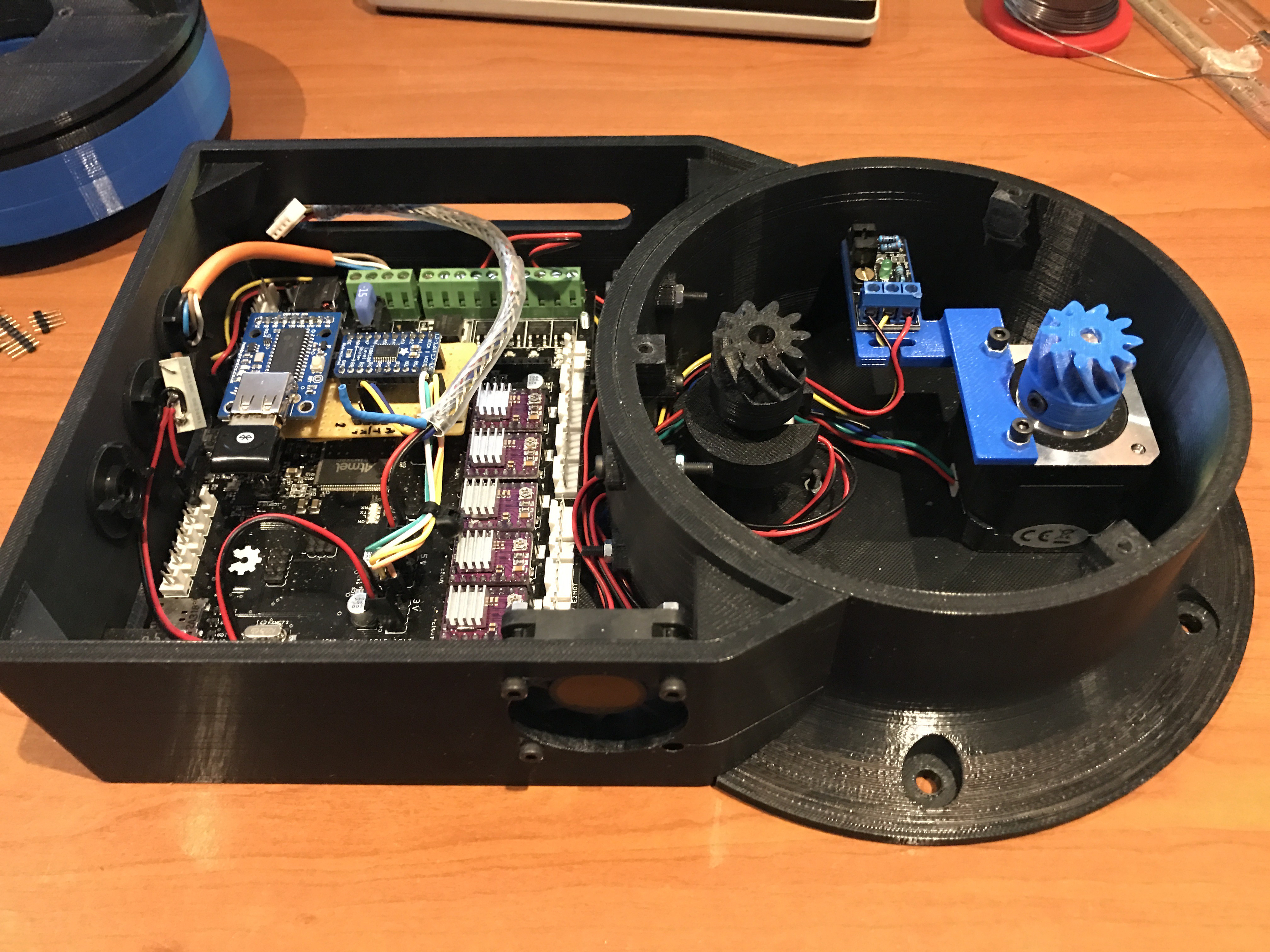
    Making room in the base, I have a motor with position sensor and feedback potentiometer wired, now it's time to add the slipring to it : -)

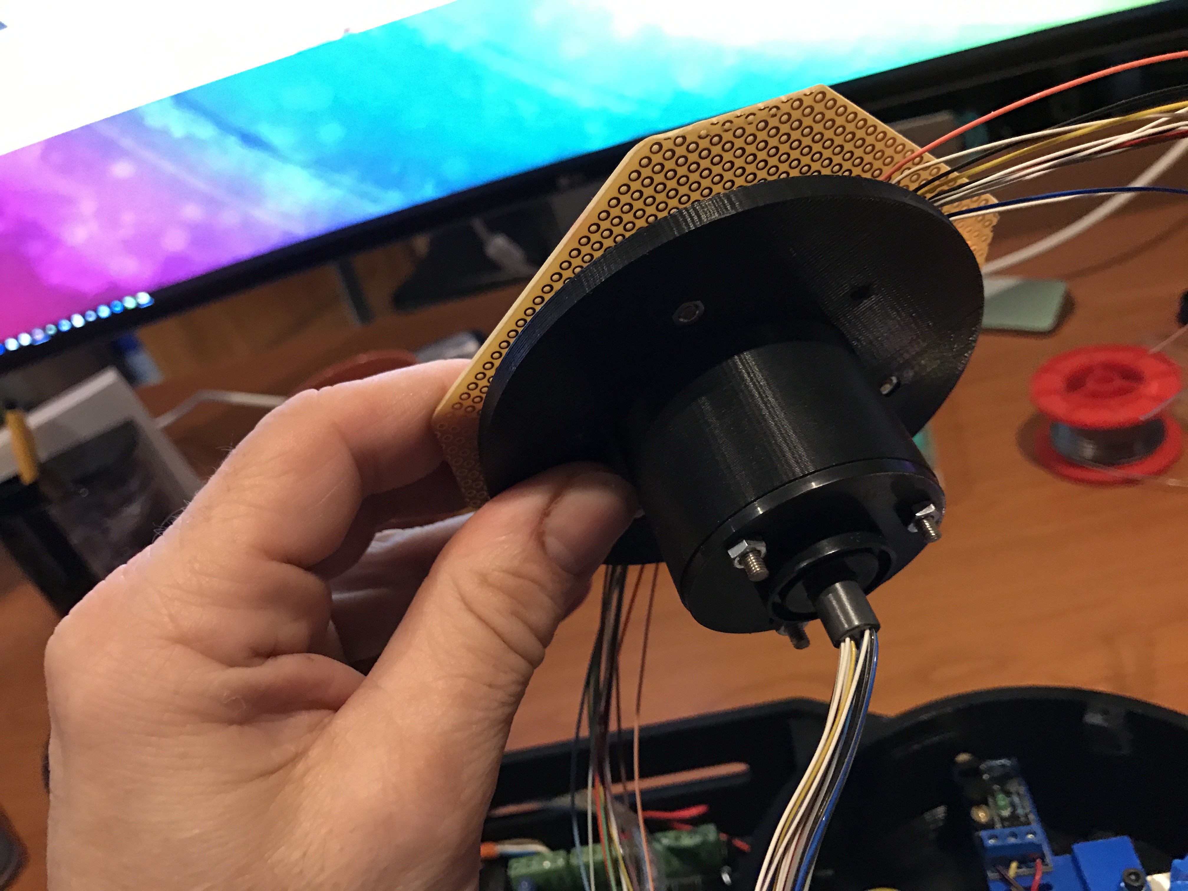
    Build my slipring into a ring that can be attached on the turning base.

    Attached pcb and connectors on it

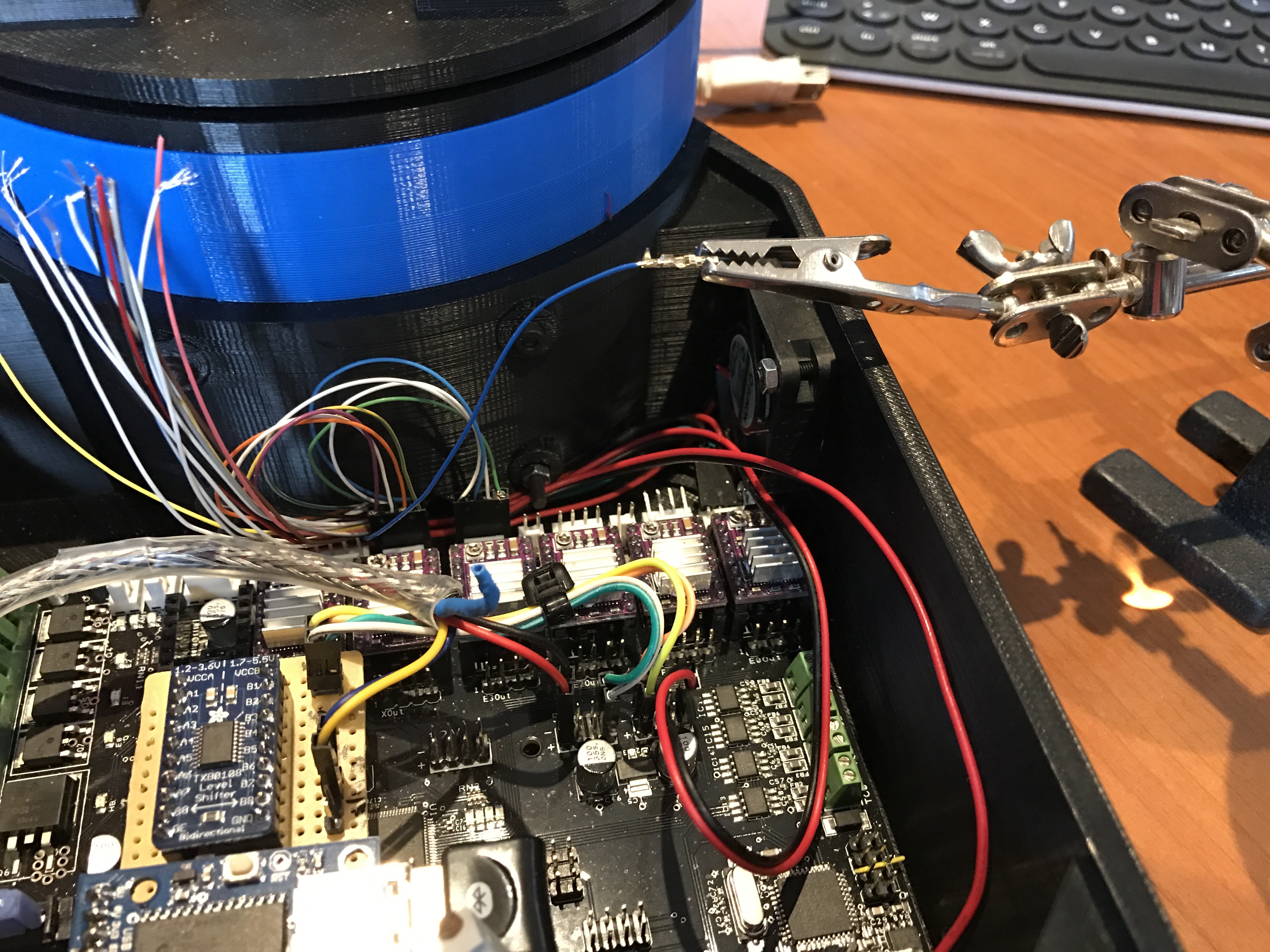
    6 steppers and 0V,5V,TX,RX for my arduino mini connectors, just to add all connectors in the controller box, very secure work adding all these small pins.

    My helping tool :-)

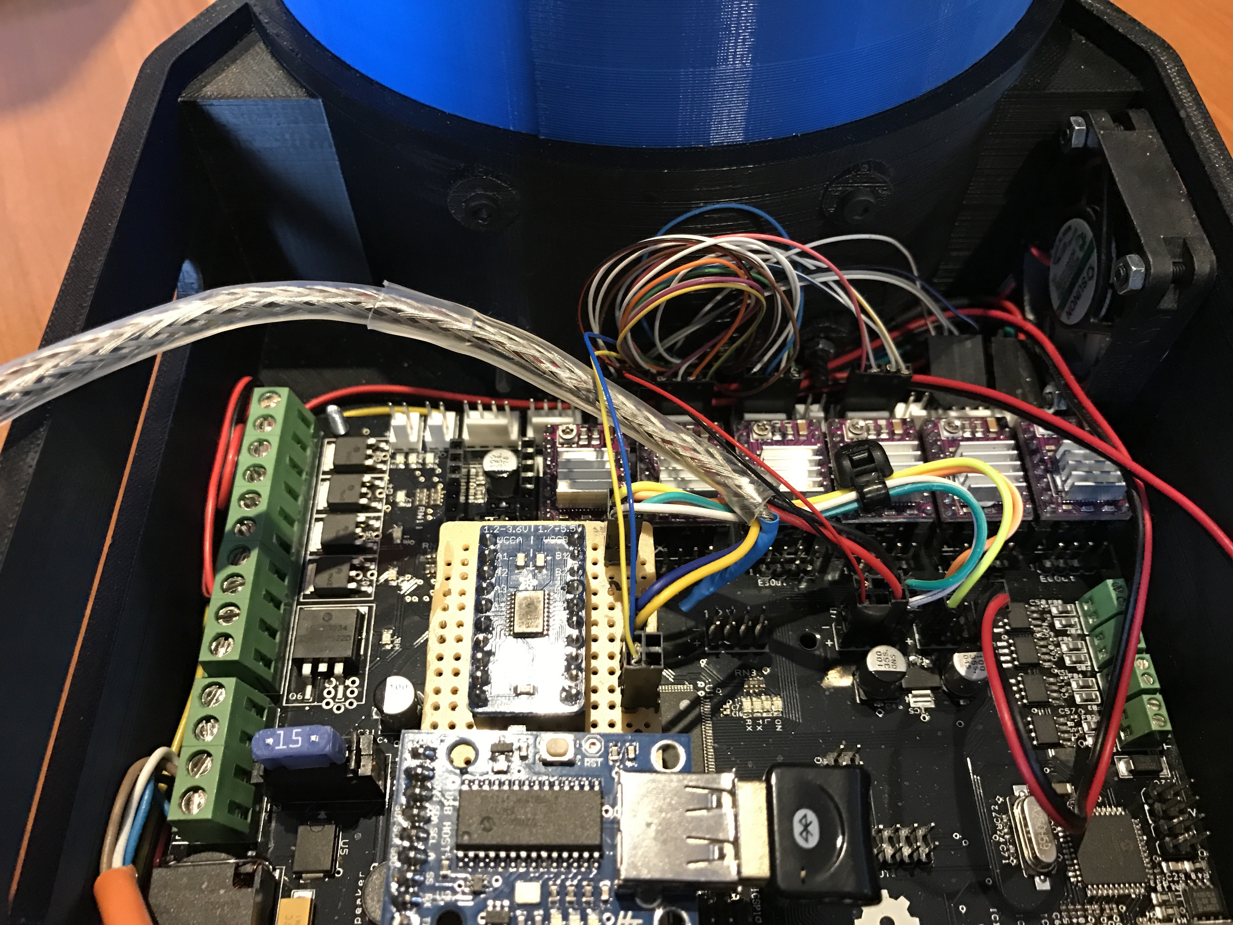
    Finnished! every wire has his connection, hoooraaayyy.

    No wire to find! That's what I wanted!

    Up to the next part, see ya!

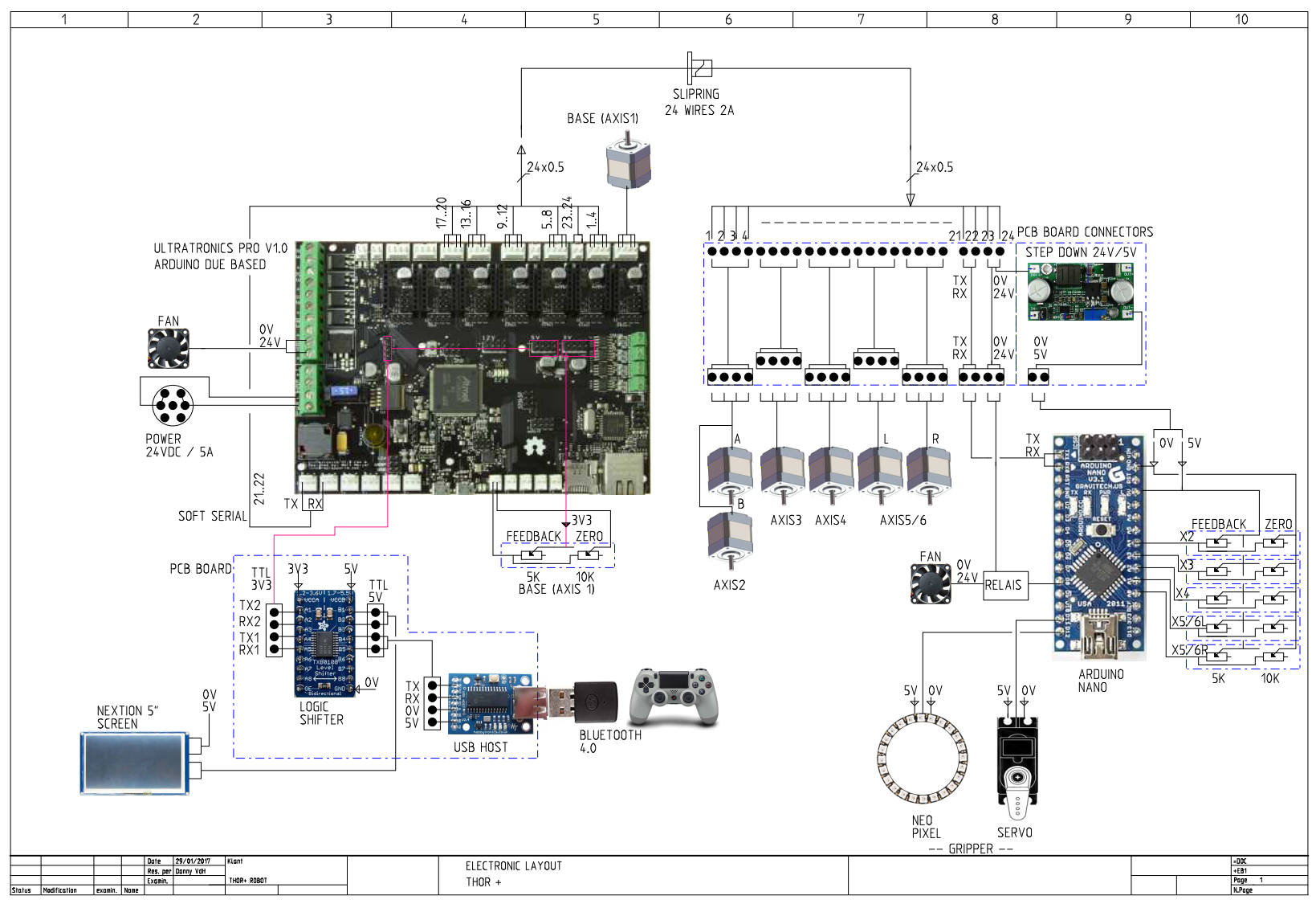
  • 'ELECTRONIC SHEET THOR+'

    dannyvandenheuvel02/11/2017 at 16:49 2 comments

    I made a complete electronic sheet of my THOR+ robotic arm
    Components used:
    1x Main controller board Ultratronics Pro V1.0 based on arduino due
    6x Polulu stepper driver 8825 cooled max 2A - 24V
    1x Logic shifter 3V3 <> 5V 8 channels
    1x USB Host PCB with flashed software PS4 controller to TTL serial connection
    1x Bluetooth dongle 4.0
    1x Slipring 24 wires max.2A for each wire
    1x Arduino Nano
    1x Neo pixel ring (gripper)
    1x Servo motor (gripper)
    1x Stepper motor (base) 17HS16-2004S1 (2A) 24V
    3x Stepper motor geared 17HS13-0404S-PG5 (400mA) 24V
    3x Stepper motor 17HS13-0404S (400mA) 24V
    2x Fan 24V 40x40x10mm

    It becomes time to assemble it! So next week I'll try to put it all togetter.
    In the meanwhile I'm gone put all drawings and stl files online this weekend.
    And after all these works I finnaly can program back on my GUI controller software :-)
    In the next comming weeks I will have a real moving robotic arm, Yeah...

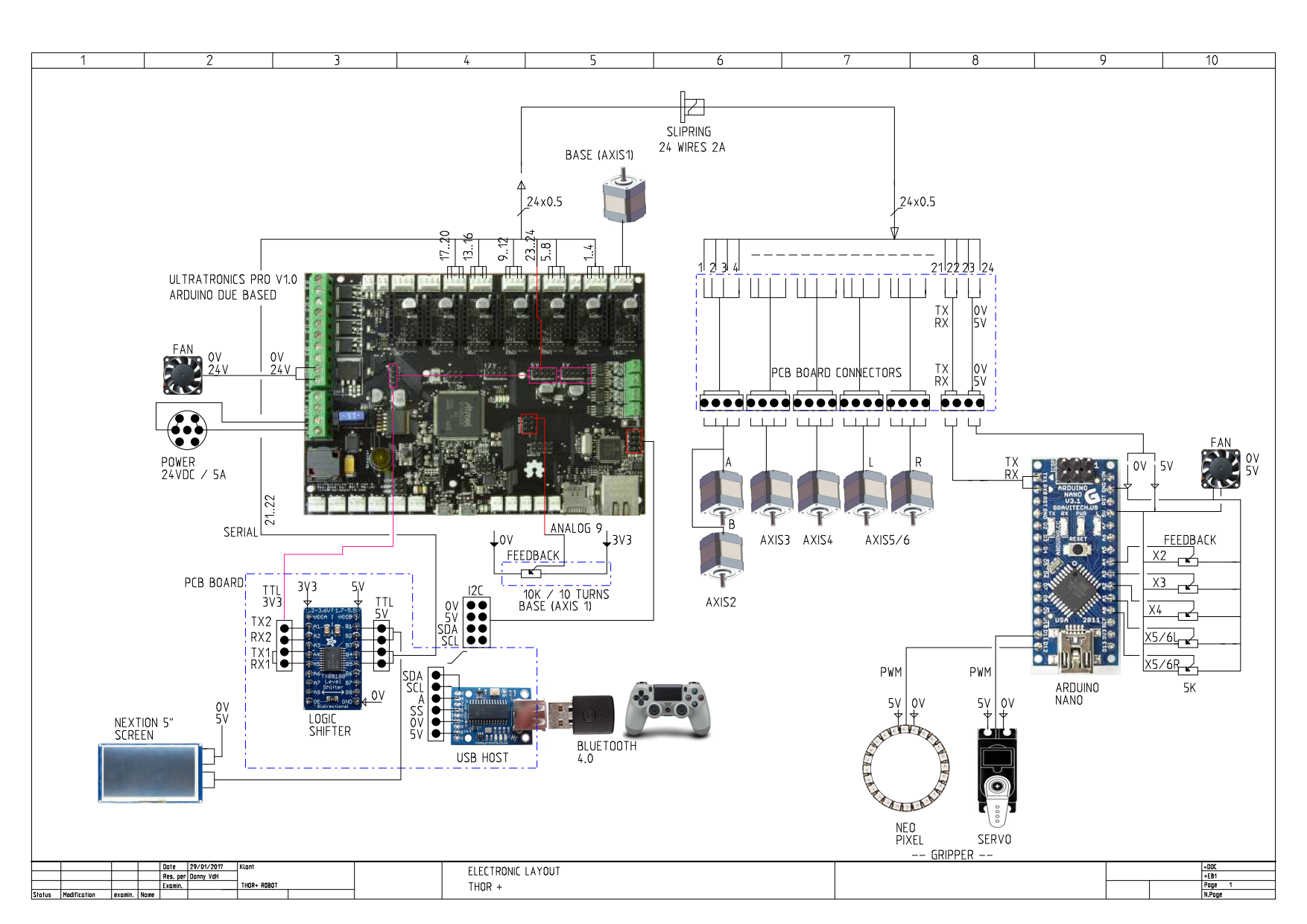
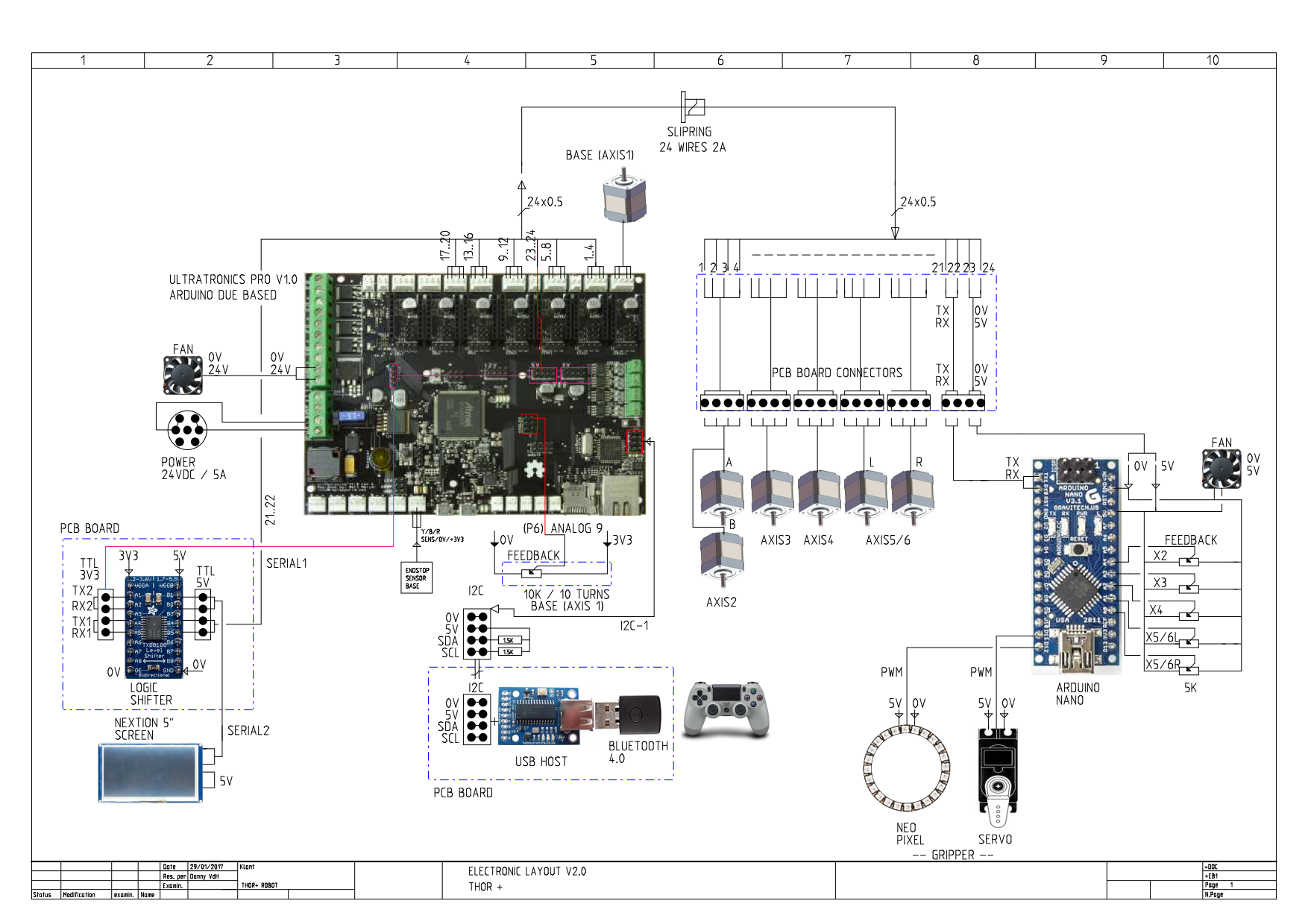
    UPDATE!!!

    Drawing has been changed, I had problems to connect to the mini arduino so had to change the communication to a real serial port. I did move my usb host to I2C.

    The base potentiometer has been moved to another analog point, don't need the extra zero potentiometer anymore.

    Removed the stepdown pcb and feed arduino mini directly with 5V and used a fan at 5V.

    Don't use de extra zero potentiometers at the other axis on arduino mini anymore.

    UPDATE LIST

    1x Fan 24V 40x40x10mm
    1x Fan 5V 40x40x10mm
    1x Potentiometer 10 Turns 10Kohm
    1x Opto board (init base) https://reprapworld.com/products/electronics/endstops/opto_endstop/

    5x Makeblock angular sensor V1 http://www.makeblock.com/me-angular-sensor

    Did some testing to use the SDA SCL at the right side on the unitronics board, a little bit tricky but it works now for 100%.
    Needed pullup resistors 1.5Kohm between SDA,SLC lines to VCC. Edit the 'ps4_i2c.h' source and changed all the words 'Wire' into 'Wire1'. Added Wire1.begin() in setup function.
    Now everything is working like I wanted it! Got a spare serial port for connection on my arduino nano.
    Don't forget to attach the usb host module on TTL/USB module and set 'SERIAL OFF' to avoid latency problems. Read the documentation very carefully from the vendor.

  • 'STANDING CONTROLLER BOX FOR THOR ROBOT ARM'

    dannyvandenheuvel02/04/2017 at 19:00 11 comments

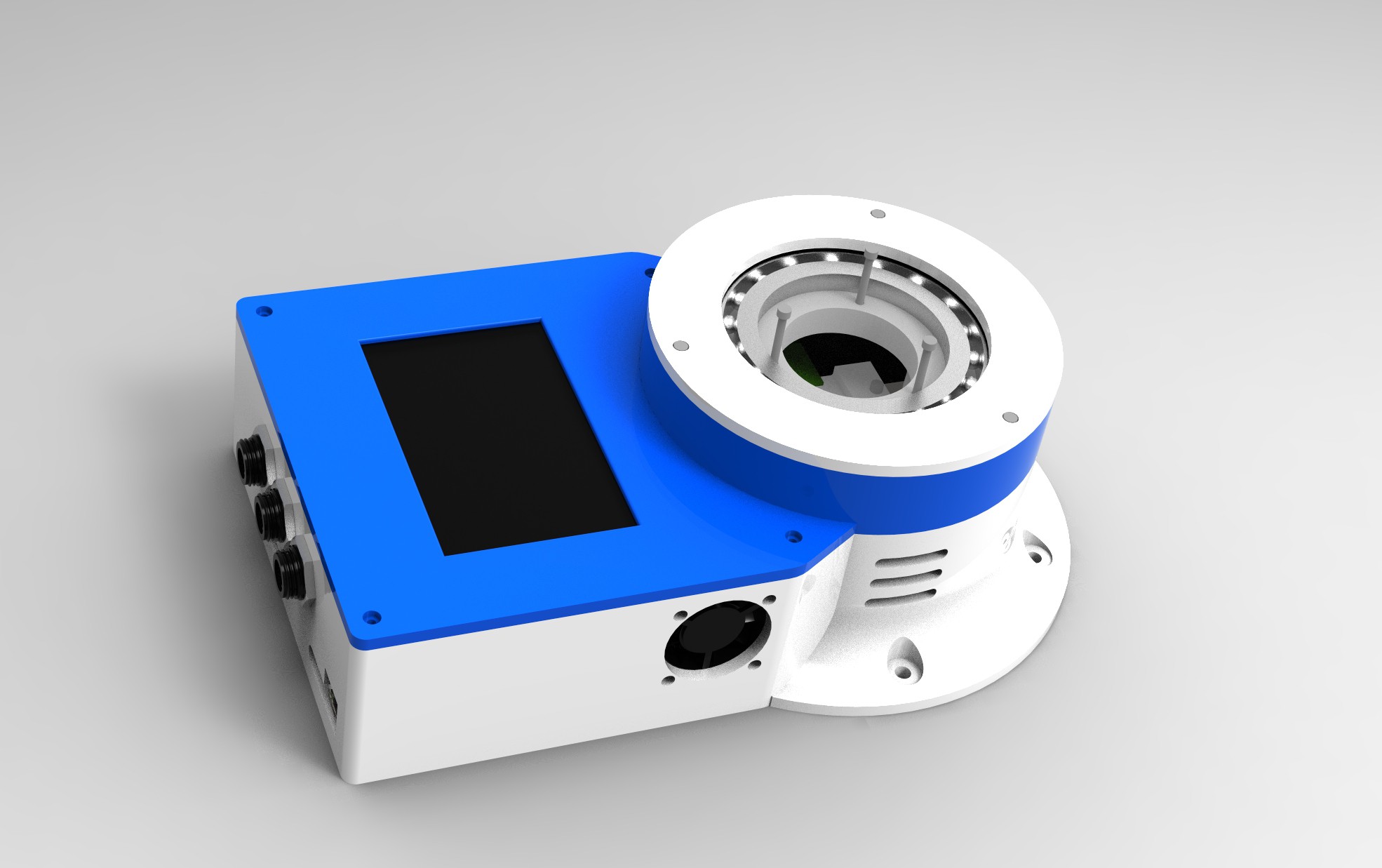
    For all those wanted a seperate controller box, there's room enough for the ultratronics pro V1.0 board, if you want a empty holes box, just ask!
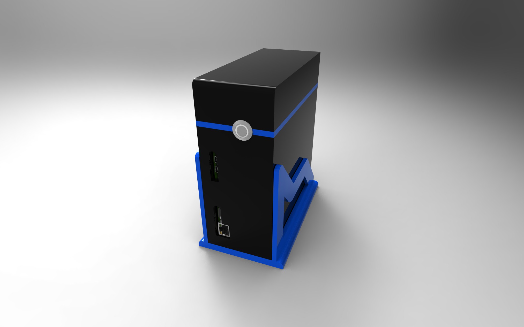
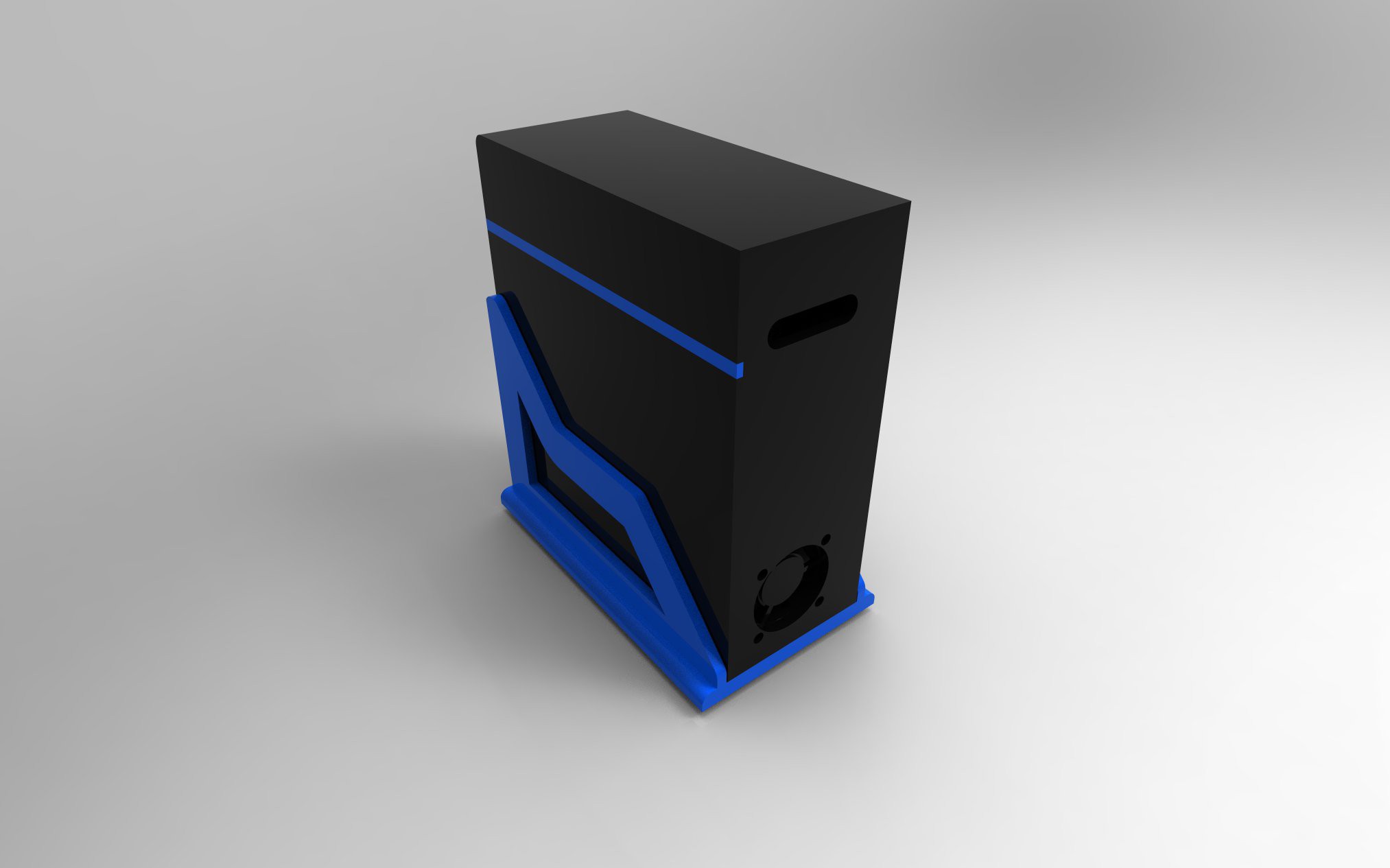
    If you want some dimensions, no problem :-)
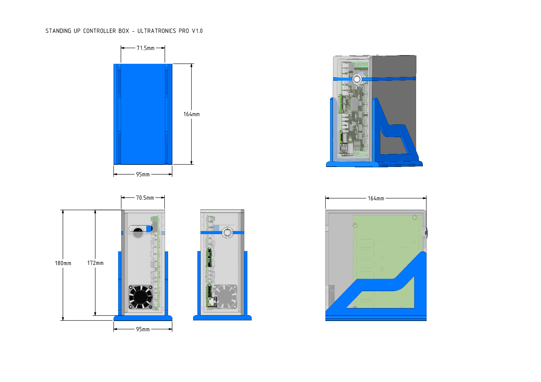
    Hope you like it! (for some personal modifications just sent me a comment!)

View all 36 project logs

  • 1
    Step 1

    Everything has been printer with stratasys Uprint SE, because some pieces where to big I changed some 3D parts, you can find them on my Github page if you have the same problem. I made them to be as strong as the originals. Feel free to ask me if you get in trouble printing it. :)

  • 2
    Step 2

    All parts has been printed, in a couple of days I will assemble THOR and make a movie and instruction list of the build!

  • 3
    Step 3

    I'am working on a graphical controle with Unity, more will be updated in the coming weeks!

View all 4 instructions

Enjoy this project?

Share

Discussions

SypherAK wrote 03/10/2017 at 21:51 point

Hi Danny, I'm playing around with the Linux-compiled GUI, and it's pretty good so far. One thing I would add in though for us that dislike sliders and want faster accuracy, would be to allow typing in the degrees for each axis instead on sliding a slider bar around. 

Keep up the great work!

  Are you sure? yes | no

dannyvandenheuvel wrote 03/24/2017 at 19:59 point

Thanks, will put it on todo list :-)

  Are you sure? yes | no

dehmel-martin wrote 03/08/2017 at 10:59 point

Hi Danny, I also want to build the Thor+ robot arm. I wanted to buy the steppers from ebay, but apparently the voltage in the product specifications differs from those given in your list. Could you check if these three products are the correct ones? Kind regards from Germany and Thanks in advance :-)

- 1x Stepper motor (base) 17HS16-2004S1 (2A) 24V:
http://www.ebay.de/itm/45Ncm-Nema-17-Schrittmotore-1m-Cable-Stepper-Motor-3D-Pinter-Reprap-Makerbot-/262199126585?hash=item3d0c492a39:g:It4AAOSwYaFWdPtI
- 3x Stepper motor geared 17HS13-0404S-PG5 (400mA) 24V:
http://www.ebay.de/itm/Planetary-Gearbox-5-1-Nema-17-Stepper-Motor-0-4A-for-DIY-CNC-Robot-3D-Printer-/262040909541?hash=item3d02daf6e5:g:A90AAOSwgNRV7pAg
- 3x Stepper motor 17HS13-0404S (400mA) 24V:
http://www.ebay.de/itm/Schrittmotor-Nema-17-26Ncm-37oz-in-Stepper-Motor-12V-0-4A-3D-Pinter-CNC-Robot-/262038536473?hash=item3d02b6c119:g:GUsAAOSwqv9V7TPh

  Are you sure? yes | no

dannyvandenheuvel wrote 03/08/2017 at 13:34 point

Hello Martin,

The motors needed to be working at 12-24V (there are a lot of motors with different power solutions, if you order from somewhere else keep in mind to get the right power connection supply!)
I've ordered mine from stepperonline. Good service, good quality! Be aware of import costs involved by ordering out of the europian union. I had to pay a extra 17% at the total amount to dhl.

http://eu.stepperonline.com/3d-printer-nema-17-stepper-motor-2a-45ncm64ozin-17hs162004s1-p-16.html

http://eu.stepperonline.com/gear-ratio-51-planetary-gearbox-with-nema-17-stepper-motor-17hs130404spg5-p-140.html

http://eu.stepperonline.com/nema-17-stepper-motor-34mm-12v-04a-26ncm37ozin-17hs130404s-p-166.html

All specs can be found at these links.

Greetings..

  Are you sure? yes | no

Olaf Baeyens wrote 03/08/2017 at 20:29 point

I did not get import cost, but maybe because watched out where the stock is coming from Germany.  e.g. '177 IN STOCK Location: Bruchsal Germany" 

  Are you sure? yes | no

dehmel-martin wrote 03/09/2017 at 20:11 point

Okay, thanks!
The Opto PCB and the Potentiometer don't appear in the list of components, but in the base data sheet. I guess they should be added?

  Are you sure? yes | no

dannyvandenheuvel wrote 03/09/2017 at 21:09 point

You can choose if you wanted to have a init sensor or potmeter or both.
I have both in my robot.
The opto sensor you will find at https://reprapworld.com/products/electronics/endstops/opto_endstop/
The potentiometer I used has 10 turns 10Kohm linear (see specs)
http://www.conrad.com/ce/en/product/429309/Precision-potentiometer-10-pos-Mono-2-W-10-k-Vishay-1-pcs?queryFromSuggest=true

I will update as soon as everything has been finished, I hope by the end of the week.
Just tweaking some last points at the drawings.

  Are you sure? yes | no

dannyvandenheuvel wrote 03/09/2017 at 22:08 point

Updated the electronic sheet and list

  Are you sure? yes | no

Luz Enith Martinez wrote 02/21/2017 at 13:14 point

Hi Danny!! Thank you very much for this greats instructions. I started building the robot arm and I was having some problems with the assembly and the electronics.  Your pictures looks amazing and are helping me to go forwards with the assembly.  I printed all the parts at school using five Ultimakers that we have at school. I started  doing Angels versions because I didn´t know about your project.  

  Are you sure? yes | no

dannyvandenheuvel wrote 02/21/2017 at 23:05 point

Hi, nice to see another Thor robot builder :-) My version has been build upon Angels version with some addons and some improvements, the electronics is very different. I'm also writing a software GUI controller on pc win/mac/linux to what the words stand for 'control and simulate' it. I'm not finnished at he moment, you can extend yours with all the tools I'm adding to it. If you have any ideas to improve or extend the project, give me a sign! See ya...

  Are you sure? yes | no

Olaf Baeyens wrote 01/31/2017 at 22:20 point

Hello Danny, if you ever get bored and does not know what to create next. One thing that would be nice is a holder to put the Ultrasonics v1.0 board in but in an upwards position with no UI displace sticking out. It would be nice if the robot could rotate 360 degrees without obstacles.

The design I am developing probably will not have an UI near the robot. But I may need a reset button to press as an emergency reset and maybe a LED to indicate the robot is operational.

I am toying with wireless communication, so the UI may be off the robot. 

I volunteer as guinea pig to 3D print it, so you don't have to :-)

  Are you sure? yes | no

dannyvandenheuvel wrote 01/31/2017 at 22:33 point

Hay Olaf,

I will see if I can make the time for it, it would be a nice extra add-on, and that's what I deliver to the project ... add-ons :-)

  Are you sure? yes | no

Olaf Baeyens wrote 02/01/2017 at 18:17 point

I love your add-ons :-) 

But take your time, tthe robot is not yet going to run away here :-)

  Are you sure? yes | no

dannyvandenheuvel wrote 01/19/2017 at 03:58 point

They asked me to split ART1BODY, I have gone a little bit further,
made 3 pieces of it with a roof that can be opened, you can bring the
middle motor into it on the other way, the structure has been a lot
stronger that way.The two other parts can be screwed togetter and be
glued. I think it will reduce a lot of time printing it and little
structures to use.
Also a fan has been forseen and the roof has some ventilation holes.

Hope you like it!

  Are you sure? yes | no

dannyvandenheuvel wrote 01/12/2017 at 17:00 point

Made ARTTOP_01 into two parts for all the people how struggle with supports. This solution will definitely help you out. After print them without supports you can glue then together, it will be strong because the screws goes to both parts!
You can download them from my page!

  Are you sure? yes | no

Olaf Baeyens wrote 01/12/2017 at 18:26 point

Downloaded. :-)
I will see if I can test it this weekend.

The original one had a 8.5 hour print job (0.3 mm layers). These 2 will take both each 3.5 hours. It shaves off 1.5 printing.

  Are you sure? yes | no

AngelLM wrote 01/14/2017 at 09:33 point

Hey Danny! Thanks for your work there :)
I have a question, what's the point of adding the cylinder at the top of the piece? I guess that can it could be used for house the screw heads or maybe for structural purpose but I'm not sure.

Thanks!

  Are you sure? yes | no

dannyvandenheuvel wrote 01/14/2017 at 18:07 point

Because the upper half was 2.5mm tick and the screws! So stability and screws sinked into the material. :-) Maybe a little bit of overkill, but I don't want to losen anything of the original strength.

  Are you sure? yes | no

AngelLM wrote 01/15/2017 at 02:09 point

That makes sense. Thanks for the explanation ;)

  Are you sure? yes | no

brett.schenck wrote 01/03/2017 at 20:33 point

Hi great mod! Will you be posting this on GitHub? I want to print your model, but not sure where to get all the parts like screws and bars. Also, where did you get your LCD screen? 

  Are you sure? yes | no

dannyvandenheuvel wrote 01/03/2017 at 22:18 point

Hi, Everything will be posted on github by the end of this week, I'm just modifying some small parts of the robot. All electronic parts are from reprapworld.com except the display, this comes from nextion www.itead.cc. All motor parts come from steppersonline.com, all other parts can be find by local dealers, most of them are 3D printer parts. I will add a full list of parts. I'm still in development with the electronics and the pc software GUI, so you will have to be patient before erverything has been finnished. 

  Are you sure? yes | no

brett.schenck wrote 01/04/2017 at 11:36 point

That's awesome! I love the the EEPROM Nextion display. It seems easy and fast to make GUIs with. I can't wait to start printing your mod this weekend. Keep up the awesome work!

  Are you sure? yes | no

dannyvandenheuvel wrote 01/21/2017 at 23:16 point

It took me a longer while to finish everything, I'm almost done, the first part (base) of thor+ version 1.0 has been placed on this project place. The next comming days I'll try to upload every other part of the robot.

  Are you sure? yes | no

dannyvandenheuvel wrote 01/02/2017 at 19:02 point

I have a complete positioning system that works,
this function I added to the stepper library and saved it to a new
library, you just have to give a position in degrees and it runs to that
point. I added a lot of things like positioning to homing sensor,
emergency stop, stop with or without holding the motor on current,
speed. It's working fine! To stay in sync and let all the motors having
the same speed when one or more motors stop I virtual keep the same time
needed to move the motor 1 step to behold the same timing if it is
running or not. I will mean, by saying it runs to that point, it moves 1
step and gets out of the routine, the next time if it isn't at position
it moves again 1 step so that there will be free idle time to do the
rest of the program. If you don't do it that way you've got different
speeds while moving more than one motor. I'm finalising this routine, it
is working, just the motors are a little bit noisy because I had to put
them on halfstep to have the fastest speed possible. I put a snippet on
my page or you can download the library.

  Are you sure? yes | no

dannyvandenheuvel wrote 12/26/2016 at 23:30 point

First glimps of my new robot controller, positioning routine stepper
motor, at the same time serial connection with nextion display at 50ms
refresh rate!
Take a look at my project page!

  Are you sure? yes | no

Olaf Baeyens wrote 12/11/2016 at 21:52 point

I  have been wondering how we could control this robot easily. 

If we have a joystick, and different mode buttons, then maybe:

Mode 1: Left = rotate base arm left, right= rotate base arm right, up= move base arm up and down = move base arm down.

Mode 2: We use the joystick as a reference point where we can point into the direction we want the arm to rotated and the speed can be varied by how far we move the stick from the center.

Mode 3: We use the robot hand as control point and use inverse kinetics to decide how to move the parts.

The important part is to switch between modes easily.

  Are you sure? yes | no

dannyvandenheuvel wrote 12/11/2016 at 22:28 point

Also on the list, joystick with analog cursors. Best to communicate with and cheapest to find are ps3 controllers. I try to spare as many resources for the main controller so it has good motor control, so serial communication must be very smal. I have now 3 motors run togetter and works perfect in sync with one degree shifted. The controller shifts every cycli 1 degree if the position isn't reached at a selected speed of the motor. If its on position it will stop and give an onpos signal, when it's moving it gives an busy signal. Parameters motor are speed,position absolute or incremental (can be positive or negative for direction, enable, steps for one revolution and microstep range 1,16,32,etc... , homing motor, and home signal. I used to work a lot with servo motors and pwm motors.

  Are you sure? yes | no

dannyvandenheuvel wrote 12/11/2016 at 21:06 point

Working on soft multithreading software to let step motors work
simultaniously. Vanish graphical display, ways to sloooow to work with,
takes to many resources. Googled the web and find cheap displays
'Nextion' with building cpu and with seperate graphical designer. Very
little resources with simple serial communication. Gone try this one.
Not at the end of my story for now :)

  Are you sure? yes | no

Olaf Baeyens wrote 12/11/2016 at 21:40 point

You are always multiple steps ahead of me. It was one of the question I was going to ask, how do you control multiple motors at the same time. I am very experienced in multi threading but this is a whole different ballpark since you have limited resources.  

  Are you sure? yes | no

Olaf Baeyens wrote 12/04/2016 at 15:22 point

Hello Danny,

I am trying to figure out where I can purchase the motors, Amazon is not very helpful but I have found this link. I have no background in motors and electronics for motors. 

I found this link: http://eu.stepperonline.com 

Are these the correct motors?

1 x Nema 17 Bipolar Stepper 12v 0.4A 40Ncm(56.7oz.in) 17HS15-0404S (€11.5 each)

3 x Nema 17 Stepper Motor 34mm 12V 0.4A 26Ncm(37oz.in) 17HS13-0404S (€8 each)

This one I am hesitating to order, since they are pricey since it has a gear-box:

3 x Gear Ratio 5:1 Planetary Gearbox With Nema 17 Bipolar Stepper 17HS15-1684S-PG5 (€31 each)

The combined cost would be €130 euros + €10 shipping costs.

To drive these motors I probably also need a power supply.

If I am correct then these motors need 12-24 V power supply, 24V would be better I expect.

Which one would be optimal for the Thor robot? Maybe with a bit to spare so I can recycle the motors for another project.

http://eu.stepperonline.com/power-supplies-c-5.html

  Are you sure? yes | no

dannyvandenheuvel wrote 12/04/2016 at 17:11 point

Hay Olaf,

Best point to buy stepperonline, motors you need
3 x geared 17HS13-0404S-PG5 ,be carefull to give up this whole number because there's a variant with a 8mm axis, you need a 6mm axis!
1 x 3D Printer Nema 17 Stepper Motor 2A 45Ncm(64oz.in) 17HS16-2004S1
I took this one over  the other 17HS16-0404S because it's a lot stronger.
3 x 17HS13-0404S 5mm axis
All step motors will run between 12-24V, I use 24V full power,  arduino + Lcd needs 5V so I used a combi power supply at conrad (It was very expensive) SUNPOWER 510402 24V - 4A / 5V - 10A. (I good power supply is recommended)
Watch out for ordering with stepperonline, I had afterwards an extra invoice from DHL with import costs 17% off the total amount. Motors came from china.

Best regards

  Are you sure? yes | no

Olaf Baeyens wrote 12/04/2016 at 21:22 point

Thanks for the feed-back!

That is what I try to avoid, import costs. 

And stepperonline seems to have a German address.

But good that you warned me.

  Are you sure? yes | no

Olaf Baeyens wrote 12/04/2016 at 21:53 point

I just ordered the Sunpower power supply. Price €99 but everything needs a good power supply. And this power supply will definitely be reused for other projects.

I had one parallella board that kept on failing, only to discover that the power supply did not give off enough amperes, even though it was written on it that it supported that.

  Are you sure? yes | no

Wilmer wrote 01/16/2017 at 17:35 point

Hello Danny, First, excellent work here. 

My students of mechatronic engineering and I are going to start building it!!!  

What would be the implications of selecting: 4 x Nema 17 Stepper Motor 2A 45Ncm instead of: 1 Nema 17 Stepper Motor 2A 45Ncm + 3 Nema 17 Stepper Motor 0.4A 26Ncm ?,  Only current consume?

Thanks in advance.

  Are you sure? yes | no

dannyvandenheuvel wrote 01/16/2017 at 20:51 point

Hi Wilmer, One of the biggest problems will be the heating in the small chambers, I'm working on the chambers to extend them with fans to have a good air flow inside of it. It's not when they are moving but when they are standing still under control. If you want to use more powerfull motors on the other joints you will have to forsee a stronger power supply, keep in mind that the small power drives going to work at 100% so they also have to be cooled down. I'm working on this issues, it's not that easy to keep it budget friendly. Stepper motors with a break could be a good solution but they will be greater in volume and won't fit into this design anymore. Closed loop would also be a better solution to keep the motor more  under control but also this will be cost a extra space for the encoder. The steppers with the gearing are strong enough because we have a factor 1:5 at strengthness on them. It's only for the tools head and there you don't need that extra power, so my advice, the only motor that can have more power will be the base, and that's what I just did.  It's not only the power but it will be faster turning around. By the end of the week all new drawings with cooling fans will be online.
I am working on a pcb board to bring all the wires togetter because it's a mess.
Read the latest notes at my page to see what I'm finishing at the moment. I strongly advice you to wait a few days when the new designs are online. As you can notice there are two version hanging around, that's the original from AngelLM and mine version. My version is still in development, at the end of the week the first prototype will be ready to completly build, the software needs a lot of improvements but manual movement isn't a problem anymore. The electronics is quite different between AngelLM and my version. You can ofcourse build you own software design, I leave it up to you. :-)

  Are you sure? yes | no

dannyvandenheuvel wrote 01/16/2017 at 20:54 point

Keep also in mind that the more powerfull steppers are a little bit higher, they won't fit in the tools chamber, you have to change the design.

  Are you sure? yes | no

Wilmer wrote 01/17/2017 at 03:38 point

Danny, thanks for answer. I understood your point. I will be waiting for your updates.

  Are you sure? yes | no

kidswong999 wrote 01/27/2017 at 18:08 point

Hi,How ablout using 3 mechaduino drivers with position feedback?https://hackaday.io/project/11224-mechaduino

  Are you sure? yes | no

dannyvandenheuvel wrote 01/27/2017 at 18:33 point

I looked at it a while ago, at this moment the mechaduino stepper motor will be to thick to fit inside the robot.
I 'm experimenting with potentiometers at the moment, I will let you know the results as soon I have tested it.

  Are you sure? yes | no

dannyvandenheuvel wrote 12/04/2016 at 22:03 point

By the end of the week I will post the compleet electrical sheets and completly documented manual how to build the electronics togetter to drive your own robot. There will be software into the arduino to communicate with the hand controller as well the control with the graphical GUI controller (The graphical controller isn't finnished for the moment so software upgrades will follow when progress has been made)
Just to let you know the progress at time moment!
Good luck with building up your own 'THOR' :)

  Are you sure? yes | no

Olaf Baeyens wrote 12/05/2016 at 18:27 point

Looking forward to it.

  Are you sure? yes | no

dannyvandenheuvel wrote 12/11/2016 at 22:51 point

Will be any days later, did some changes so it has a little delay, try to bring them online in the next comming week!

  Are you sure? yes | no

guiducci.alessandro wrote 04/24/2017 at 09:36 point

Hi Danny, did you posted the manual how to build the electronics together, ? I'm planning to start your project but before i'd like to be sure to be able to do it  :-) last question, Up to you should be possible to use a Ramps board? thank you very much for your time!

  Are you sure? yes | no

Bobby Feather wrote 12/03/2016 at 16:38 point

When I get my new 3d printer I am defiantly building this for me and my son to build. 

  Are you sure? yes | no

Olaf Baeyens wrote 11/30/2016 at 22:36 point

There is one thing not very clear in the project. I see the controllers, I see the motors, but where is the power supply to provide power to the necessary motors?  I can't imagine that it can fit in the Thor housing.  And how big would that one need to be?

  Are you sure? yes | no

dannyvandenheuvel wrote 11/30/2016 at 23:37 point

I use a labo dual power supply for the testing at the moment. The power supply will be 5VDC and 12VDC. It's not that small so it has to be into a separate box. The power consumption has to be calculated, I am using 5A for the 5VDC and 10A for the 12VDC at the moment.
I am thinking to make a box under the base feet.
Also my motor drives are outside the robot because I used some overdimensioned drive controllers with cooling ribs. That's why I work with a seperate connector box on the base to go to a controller box. This project will needs it's time to completely be finished.

  Are you sure? yes | no

Wilmer wrote 11/22/2016 at 16:18 point

Excellent work!, I am going to building it. Could you post your github address?

  Are you sure? yes | no

dannyvandenheuvel wrote 11/22/2016 at 21:16 point

Hay Wilmer, you can find me at https://github.com/Danny-VdH , all stl file can be downloaded from there or here at my project page.
greetingz..

  Are you sure? yes | no

Hans de Bruin wrote 11/21/2016 at 19:00 point

Hi Danny, thanks for splitting the art2bodyA and B into two halves. Great work.

Would you also be so kind as to make the basebot a tiny bit smaller? It is now only a few millimeters too big for my Ultimaker. I have tried to export it from Freecad to Solidworks but that didn't work very well. 

I tried to edit it in Freecad but the model is a bit strange. I can't find or modify any part in it. But I'm not familiar with Freecad... I've tried to copy the model in Solidworks but the measurements are a bit strange.

If you could trim 5 mm from the outer edge that would really help me.

Thanks. 

Hans

  Are you sure? yes | no

dannyvandenheuvel wrote 11/21/2016 at 19:39 point

Hay Hans,
You know my version of thor is made of two pieces, a connector box and the base itselfs. The outer diameter is 200 mm, you want this 5 mm smaller or 10 mm ?
The maximum I can reduce without changing the holes will be 10 mm , a diameter of 190 mm. Tell me what you want and I will make a special version for you :)

  Are you sure? yes | no

Hans de Bruin wrote 11/22/2016 at 07:37 point

Hi Danny, 

I also tried your version but it still is a bit too large. If you could change the outer diameter to 190 mm that should work.

Thanks for your help!

  Are you sure? yes | no

Hans de Bruin wrote 11/25/2016 at 10:12 point

Hey Danny,

I finally figured it out!!! Freecad is a bit difficult to understand sometimes. But I  figured out how the base was drawn and I was able to edit the sketch to make the diameter smaller.

So I can print it now.

  Are you sure? yes | no

dannyvandenheuvel wrote 11/25/2016 at 10:27 point

OK, nice

  Are you sure? yes | no

dannyvandenheuvel wrote 11/20/2016 at 22:56 point

Part 2!  Thor ROBO_GUI , playing with cubes. go to my page to see it with your own eyes :)

  Are you sure? yes | no

dannyvandenheuvel wrote 11/20/2016 at 22:37 point

I'm also thinking to remove them because they will be glued togetter, I will change the drawing.
Thanks!

  Are you sure? yes | no

dannyvandenheuvel wrote 11/20/2016 at 22:25 point

Hello Olaf,
You have to bring the two motors first in the lower part, don't tighten it to strong, you have to move it up and down. Bring the second part with the belts hanging over the gears. When the two are fit togetter bring te belts over the pully and tensioning the belts.
Hope it helps :)

  Are you sure? yes | no

Olaf Baeyens wrote 11/20/2016 at 22:02 point

Hello, 

I printed ARTBODY_1 and ARTBODY_2.  I noticed that you have provided a rim and 4 bolts holes.  ARTBODY_2's rim is blocking the entrance of the 2 nuts into the lower nuts holder. 

Maybe you could alter these 2 nuts holders so that the holes are at the side.

I glued these parts together and I don't think that the rims are needed, just gluing these parts it together makes it very strong.

If  you can lose that rim then you also can print faster because you do not need a support structure that high.

Both ARTBODY_1 and ARTBODY_2 are about a 7-8 hour print.

  Are you sure? yes | no

Similar Projects

Does this project spark your interest?

Become a member to follow this project and never miss any updates