Vitaly
-
Firmware on bare metal
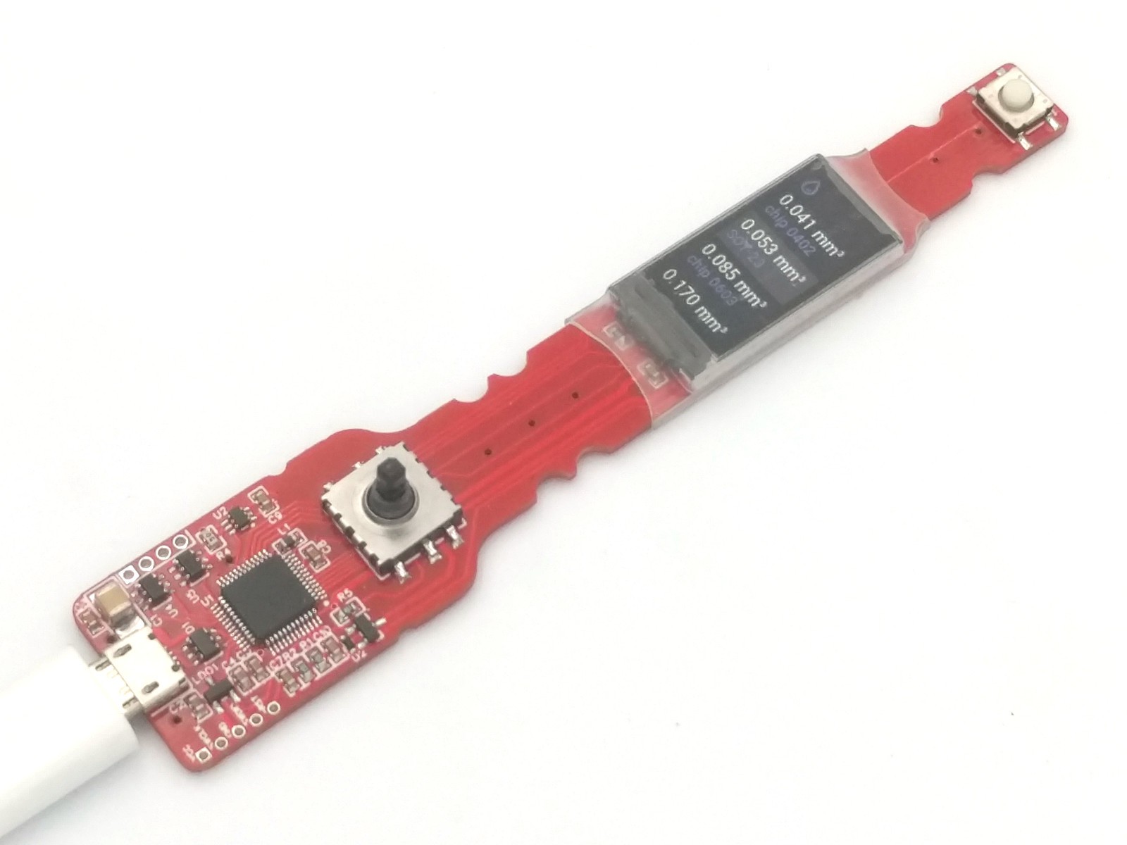
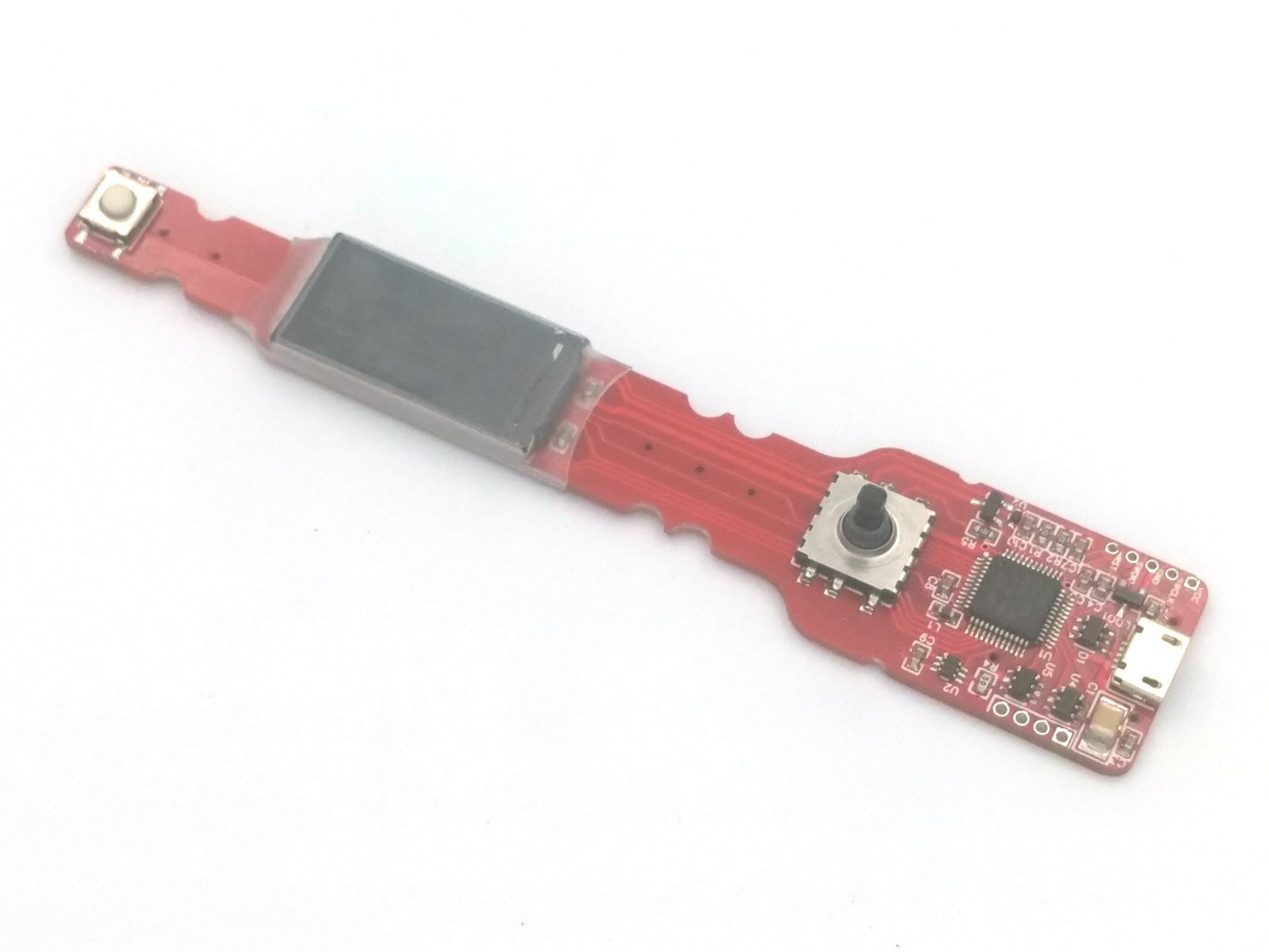
01/11/2020 at 15:13 • 0 commentsGood news, project is alive and goes forward :). PCB works and can show all those nice things from simulator, with subpixel font smoothing:
![]()
USB uploader also works. Very convenient for users - ST-Link/V2 not needed at all.
I started to write assembly manual. It's not complete, but enough to understand simplicity. Feel free to PR grammar fixes, because english language is not native for me :).
Minor tech notes
Found small issues, not enough to create next PCB version, but worth to remember for future works:
- LCD Backlight resistor should be reduced from 20 to 10 Ohm.
- Probably, backlight transistor not needed at all. It doesn't seem brightness needs tune. Also, this can be done via styles of LVGL widgets.
- It would be nice to increase size of TVD diode in dispense button filter. But it's needed only if you wish to attach pedal with long wire, and can be not mounted at all.
What's next?
Plan is to learn how to use 3D printer, and print all plastic components (openscad drafts have been pulished on github. Then we can start debug dispense algorithm. Goal is to auto-tune on the fly all params (speed, retract level) via motor current sensor. But it's difficult to predict in advance, is it possible to to this with desired quality or not. I think, in 2-3 months we should get something final, ready to use.
-
PCB v3
11/28/2019 at 22:46 • 2 commentsAssembled third version of PCB:
![]()
- Added current monitor (in theory, should help to autodetect retract size).
- Fixed BOOT pin control, to allow firmware upload via USB.
- Added holes for wire pins to lock plastic supports.
- Debug pins grouped in line.
My friend, second author of our sensor-less speed control for grinder decided to join this project too. He will help with drivers debug (current firmware runs in simulator only). And i will continue with reflow micro table for this time.
Sorry for slow updates - that's specific of OSS development. Instead of doing single project, i prefer to do multiple things in parallel. This allows to share efforts, and each can pick preferable parts where he is most qualified.
-
Interface polish & hardware rework
10/12/2019 at 08:35 • 0 commentsInterface
Everything become better if done by professionals :). Since i have no illusions about my own skills, i usually forward art-related parts to designer. Here are screenshots of new interface:
![]()
![]()
![]()
IMO looks nice. Current demo will be updated soon.
Hardware
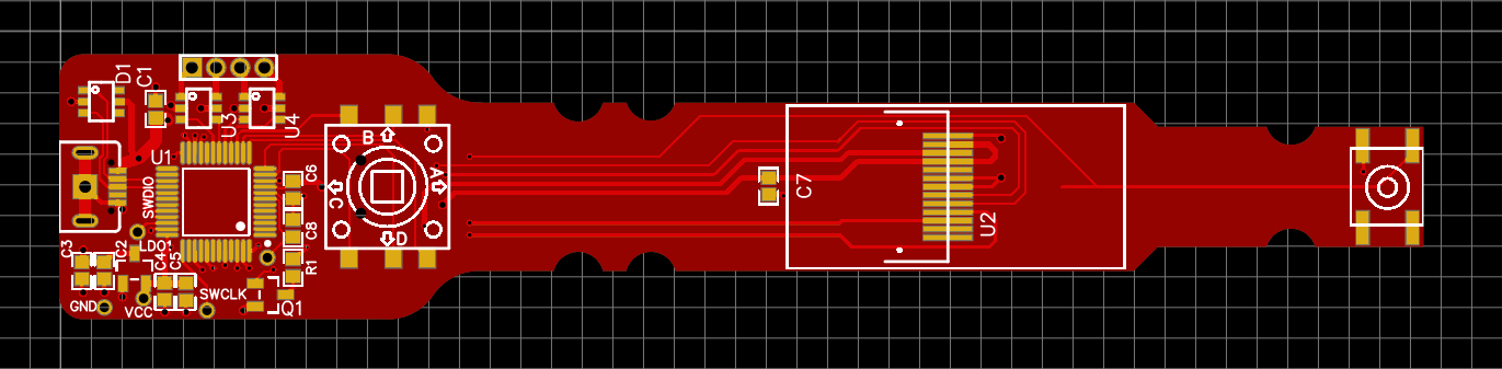
After some reviews, decided to do one more iteration prior to start bare metal debug. Updated schematic & PCB https://easyeda.com/puzrin/dispenser:
- Fixed (i hope) USB firmware upload.
- Remapped MCU pins for better traceability.
- Added current sensor - important for automatic retract calibration.
- SWD pins are grouped in line again.
- Returned back push-button filter. Now it's safe to attach external pedal if desired.
- Rounded PCB contour in some places.
- Moved SMT reference holes to more convenient locations.
- Added holes to make locks for plastic supports, if you don't wish to glue those forever.
Will take couple of days to recheck everything, and then order new PCB, SMT stencil & components.
-
Dispencer PCB v2
10/07/2019 at 19:36 • 0 commentsReceived new PCBs. Still not final, but looks sweet:
![]()
And with 1cc syringe (supports are not final, only for prototyping):
![]()
Also, i got very useful advice about align SMT stencil with reference points:
![]()
I did two 0.7 mm holes and used 22 Ga (0.65 mm) SS wire from vape to pin PCB & stencil to cork sheet. That position stencil very easy and very precise. When you make order at JLCPCB, stencil adds ~ 8$ - very low price for comfort assembly. The only thing you need to do - select custom size and reduce default to minimal possible.
Note, PCB still needs some care. Don't order now if you have no plans to join development :)
- Missed BOOT1 pin control to allow USB firmware upload (without st-link). While development - not critical.
- Not sure LCD backlight needs transistor. It takes 20ma only and should work from MCU pin directly. Though, direct power may be not good for ADC.
- I tried to avoid that... but... seems it really worth add motor current monitor. That should help to autodetect retract size & max dispense speed.
- Worth to add more 0.7 through holes to lock plastic supports with 22 Ga wire pins.
With all those changes, i probably will add 5mm to PCB tail.
-
Firmware: interface prototyping
10/02/2019 at 06:26 • 0 commentsIt may sound strange, but in many devices the most time-consuming task is interface prototyping and polishing. Good news is, there exist embedded GUI libs with desktop support. If you design application properly, you can do almost everything on PC, without real hardware at all. That reduces development and debugging time in x10 times and more.
![]()
I selected LittlevGL. It's not ideal, but can work on MCUs with small memory.
As perfectionist, i don't like compromises about quality. So, to make LVGL "useable", i had to design new storage format for bitmap fonts and create appropriate font convertor. Here is the result:
This tool properly uses kerning, autohinting and allows create nice texts on display. See animated demo above. Now you can just take TTF or WOFF font, and convert it for embedded use without quality loss. Of cause, convertor allows merge multiple fonts, select subsets and so on. Data format is universal and not limited to LVGL only.
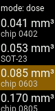
Lets return to dispenser interface. As you can see on image, it has 3 "screens":
- "Dose" in this mode, dispense button click produces fixed portion of selected volume.
- "Flow" mode - dispenser works until you keep button pressed.
- "Settings" - setup hardware options, needed to calculate optimal dispensing speed.
Controls is done with 5-way tactile switch + dispense button:
- up/down - move selector position
- left/right (settings only) - change selected value
- short "enter" - switch between modes (dose/flow), long "enter" - go to settings.
Seems convenient. Next step is to ask designer draw everything "properly".
Source code with current progress available on github: https://github.com/puzrin/dispenser. If you need more details about abstracting hardware, you can find those there.
-
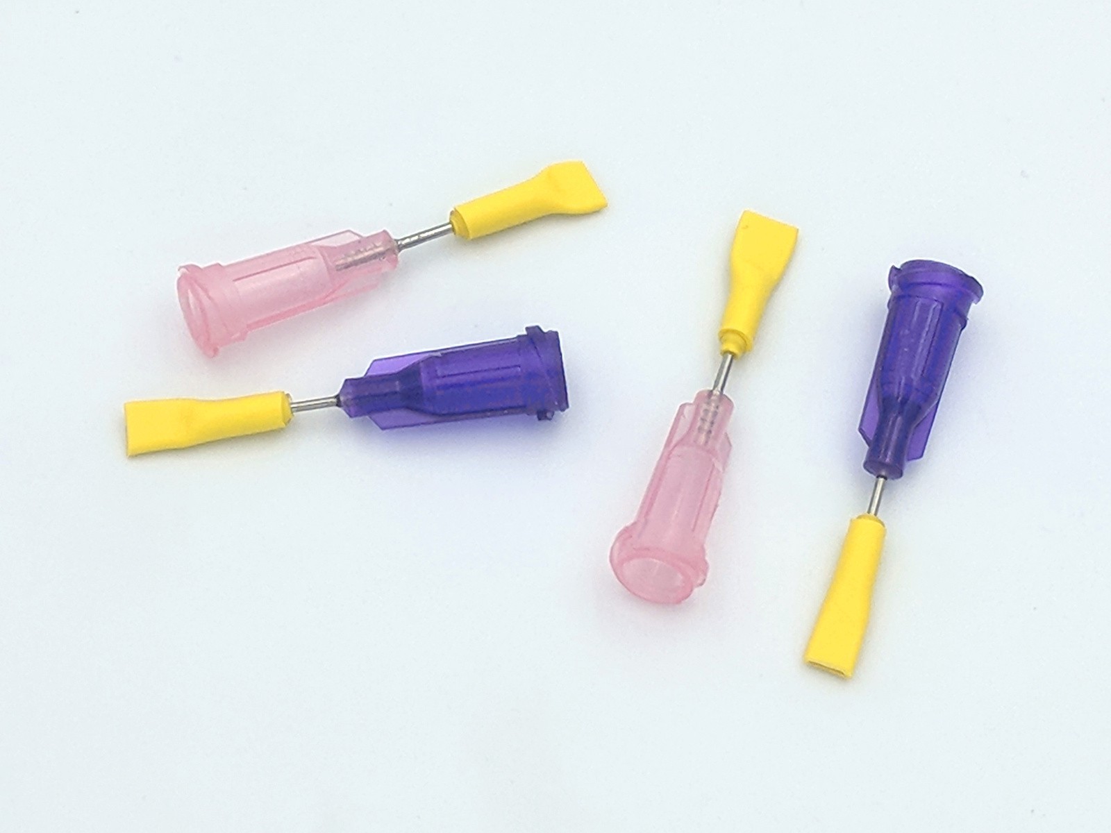
Tip: needles caps
09/03/2019 at 14:41 • 0 commentsThat's a side note, not directly related to dispenser, but very useful. When we not use syringe, needle should be closed to protect content from drying. Here is a recipe, how to organize things with ease.
First, if you need professional use, and have a lot of space, the best approach would be to keep syringes vertical, with needle in glycerine bath. But.. let's be honest... that's too much for rare hobbyist's use :). And most of us don't care to keep soldering paste in refrigerator. We just need small cap to restrict air access.
This can be done with heat shrink tubes. Original recipe, i was advised, suggested use one fat pipe and thermal glue to close the end. I used a bit different approach:
- Small tube, 1.5mm with 1:3 ratio
- Bigger tube, 3mm, with glue layer & 1:3 ratio
First, shrink small tube to needle and cut it at needle end. Then shrink bigger one and squeeze the end. See result:
![]()
Then add a drop of silicone oil for additional safety. You can vary approach, use 1:2 ratio tubes and so on. But principle is the same.
Hope this helps!
-
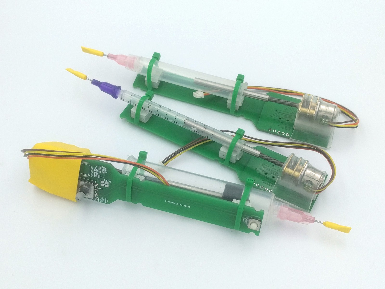
First prototype
08/11/2019 at 08:23 • 0 commentsSince PCB-s are very cheap, it's convenient to make draft prototype and check how it fits in hands. Here is photo with different syringes:
![]()
This is NOT expected to work, only to test mechanics, materials, size and so on.
Thoughts and observations:
- Back plates of syringes should be cropped (not convenient to keep in hand). This can be done with wire cutters, and then trimmed with sandpaper or knife.
- On install, syringe can "sharp" supports. To workaround - one part of backplate should be deleted, and another one used as "lock". See photo above.
- RGB led is too few for convenient control. Fortunately, there are some room on the head for small IPS display (there are smaller OLED displays, but this one seems very nice for cool UI).
- Pedal connector is not high demanded feature and occupies a lot of space. Remove to reduce board size.
- Replace debug connector with independent pins, to save space. It's required for developers only. End customers will use USB to upload firmware.
That's the most notable things. Here is render of reworked PCB (source - https://easyeda.com/puzrin/dispenser):
![]()
Seems nice. Need to meditate some days before new order, may be new ideas appear.
-
Pusher
08/11/2019 at 07:45 • 0 commentsThere are 2 major pusher approaches - with rotating rod and rotating tube. Let's leave aside rotating tube, as it's more complicated for DIY. So, we need cylinder with M3 inside. Here are 2 choices again:
- 3d printed cylinder, with brass insert reinforcer.
- Full metal (tube with M3 thread inside).
All appropriate drawing for 3d print are available on github. But for 1cc syringe detail will be too thin - metal pusher needed. Can we do it good enough without lathe? Yes. We need suitable tube and make thread inside.
After experimenting with lot of available materials, it seems optimal use SS tube ID 4mm OD 2mm (description says ID 2.5 mm but it's 2mm). This material is a bit not convenient for drilling, but nothing impossible. So, we need:
- Good M3 tap (2-passes preferred). Cheap aliexpress 1$ taps were not tested.
- 3.2 mm & 2.7 mm HSS Co drill bits (on aliexpress - search "M35" drill bits).
- Vise and electric screwdriver.
To make holes straight, put tube into screwdriver and push with static drill bit (use separate chuck to hold it). After some training, that's not difficult:
- Cut 45mm tube peace.
- Drill through 2.7mm. Use max RPM to reduce screwdriver chuck axial vibrations.
- Drill with 3.2mm about 35-38mm to leave about 7mm for the thread.
- Make thread.
Here is a result:
![]()
Small pieces of soft adhesive tape add friction with syringe body and exclude rotation on install.
So, even for 1cc syringe, everything can be done at home, without advanced and expensive tools.
Next step is prototype assembly & testing to it fits in hand.
-
Attaching threaded shaft
08/10/2019 at 12:33 • 0 commentsTo push paste out of syringe, we need threaded shaft. There are 2 ways:
- Use coupler and threaded rod
- Use gearbox with built-in long threaded shaft
Coupler with threaded rod
You can take this coupler 2.3mm to 3mm. Use 2.5 mm drill bit to enlarge hole, then tap M3 thread and insert 60mm M3 rod or screw with loctite.
Disadvantage is loosing 20mm of movement length (or increase length of device). Let's leave this for Plan B.
Gearbox with built-in long shaft
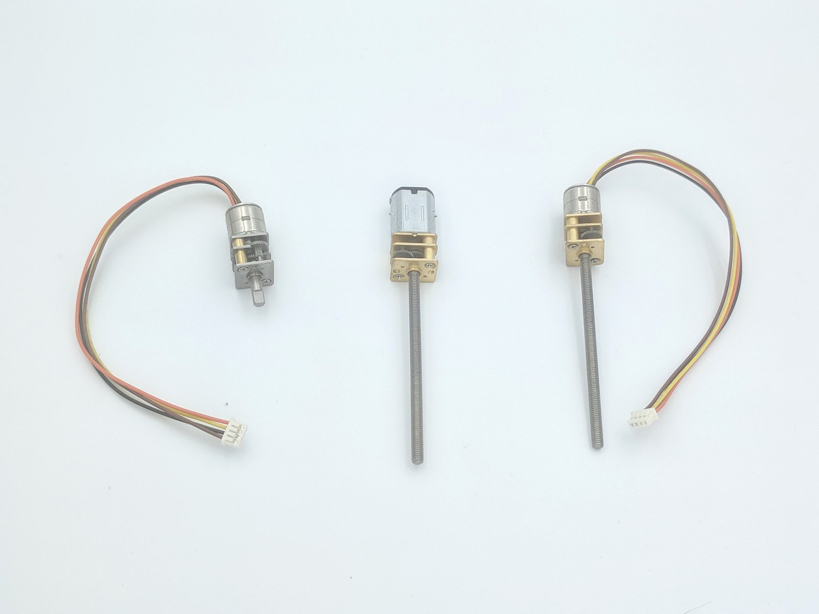
There are no ready mini stepper solutions with M3 shafts, but we can assemble it from two donors:
- Mini stepper. Any of this size (10mm) with metal gearbox will be ok.
- Gearbox with 50mm M3 shaft from Brushed NV20 motor (you need 30RPM version).
In may sound strange, but those parts are compatible!
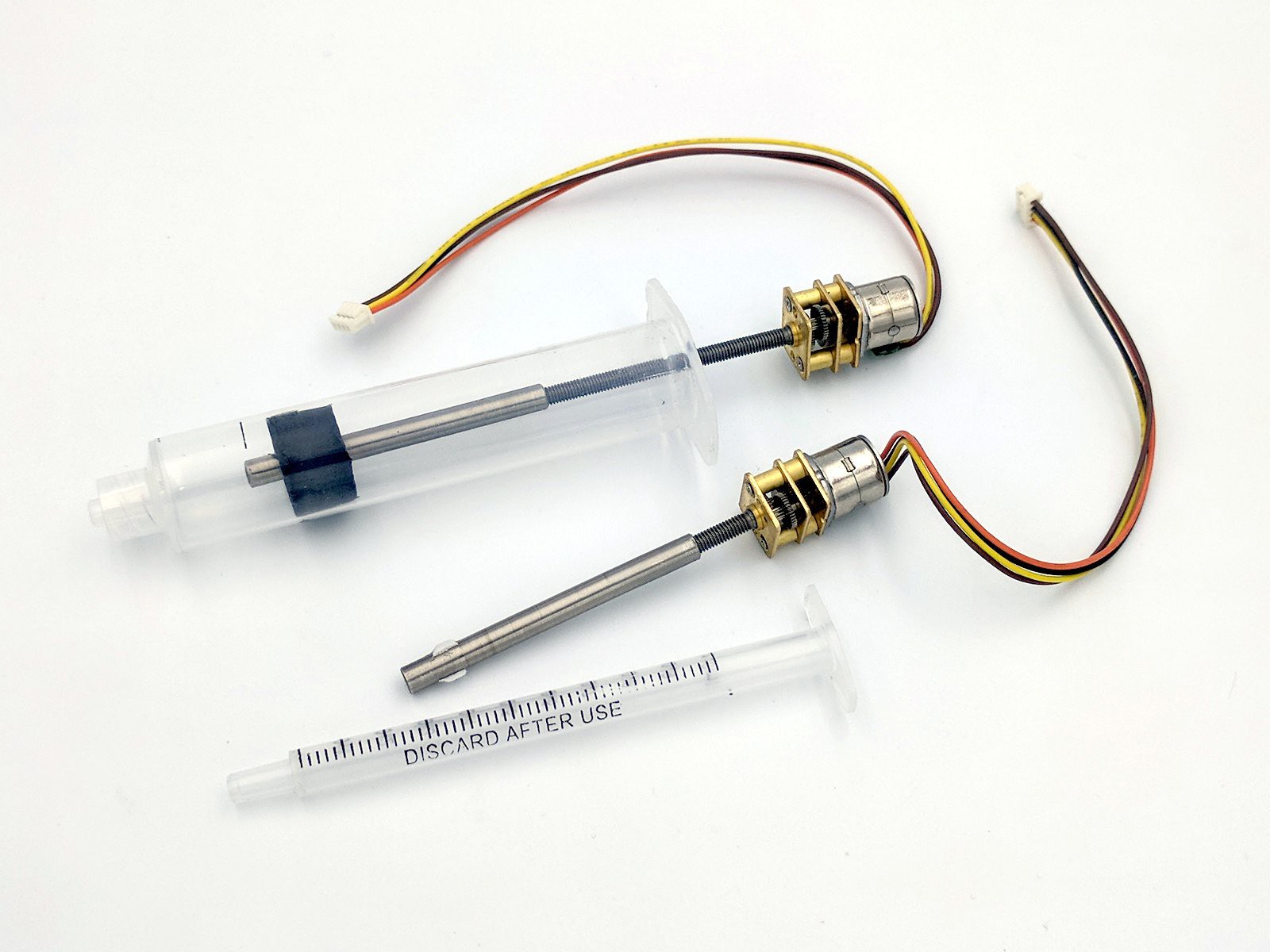
![]()
See photo. Donors are on left side, result on right side. Total cost with delivery will be about 10$. Not ideal price, but acceptable, requires zero efforts and is the most compact.
If you decide to combine other components - check gearbox sizes, those should be equal (the most popular can have 10x12mm or 12x14mm plates).
If components go out of stock - we still have Plan B with coupler. Both solutions do not require complicated tools and can be reproduced by anyone.
-
Motor & gearbox
08/10/2019 at 06:33 • 0 commentsMany hand made dispensers use 28BYJ-48 motors. Those are very cheap, but not enough small and not convenient to mount. We need something better:
- More compact.
- Precise enougth.
Let's estimate desired gearbox ratio.
All small 10-15mm steppers usually have 18° step (20 steps per turn). Gearbox can be:
- Plastic. Usually up to 1:50
- Metal. Up to 1:295 (sometime up to 1:600)
Other data:
- Pusher uses M3 shaft with 0.5mm pitch.
- Inner dia of 10cc medical syringe is about 15mm (a bit more for pneumatic syringe, but not principal now
- Volume of paste for 0603 resistor pad is ¹/₁₂ - ¹/₁₆ mm³.
- Let's say we need to dispense one 0603 portion with precision about 10%.
Desired portion size per single motor step is 0.006 mm³.
Let's calculate, what stepper with plastic gearbox 1:50 can give us:
(3.14 * 15² / 4) * 0.5 / 50 / 20 => 0.09
0.09 mm³ is very bad. It's 1.5x more than portion size and 15x more than desired precision. What can we do?
- Use metal gearboxes with better ratio
- Decrease syringe dia (use 3cc or even 1cc)
1cc syringe has dia about 5mm. Portion per step will decrease in 9x. Better, but not perfect. Let's use metal gearbox 1:295.
Estimate for 3cc syringe (9mm inner dia):
(3.14 * 9² / 4) * 0.5 / 295 / 20 => 0.005
Estimate for 1cc syringe (5mm inner dia):
(3.14 * 5² / 4) * 0.5 / 295 / 20 => 0.001
In total:
- 3cc syringe & 1:295 gearbox - 0.005 mm³ per step, very good for 0603 components. With some reserve for smaller pads.
- 1cc syringe & 1:295 gearbox - 0.001 mm³ per step, should be enough for all.
Of cause, we could use dynamic model (quick step forward and back) and cheat with paste viscosity. But that's much more complicated and result will depend on paste temperature. Also, it's not good idea to use micro stepping, because it's not precise with cheap motors and consumes more power.
Conclusion
- Mini steppers with metal gearboxes are preferable over plastic ones.
- 3cc & 1cc syringes are most optimal for soldering paste.
- 10cc syringes still may be interesting for fluxes and glues.
That's all with boring maths, next time I'll try to post some pictures :)