Federico Runco
-
Test drive on SuperTuxKart
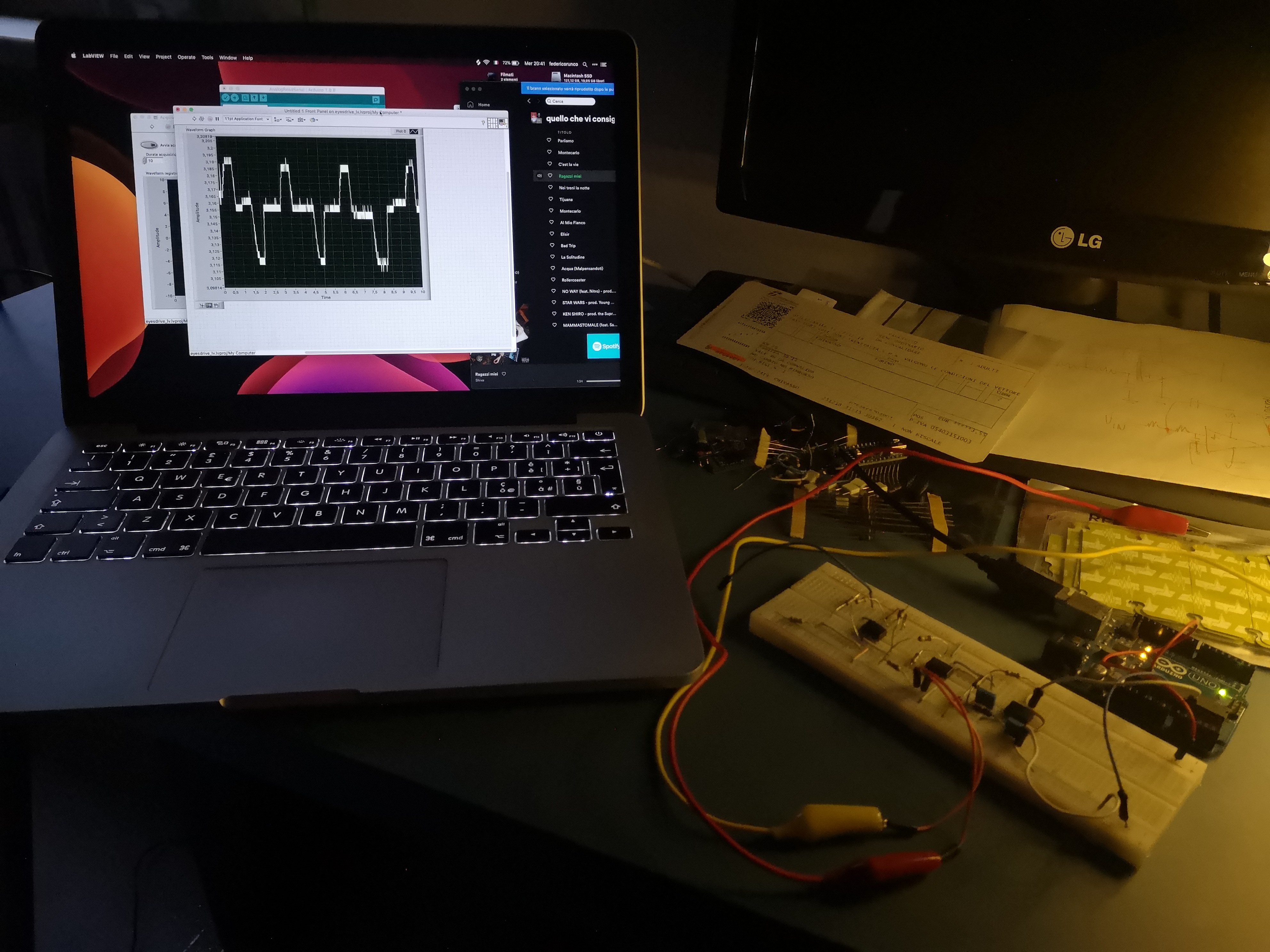
04/26/2020 at 19:57 • 0 commentsSo while I'm waiting for the new PCB to arrive, I recorded this test where I steer a kart in SuperTuxKart only with my eyes.
The AFE used in this video is on breadboard and communicates with the PC via USB, in the final version it will communicate with the host device via Bluetooth.
I've implemented a rough Leads-off detection algorithm via software (no hardware components) that works pretty well, I think I'll keep it in the final version.
The PC side software is written in Python, is a simple script that reads the serial port, splits the data and emulates keyboard combinations according to the data received. If a LOD event is triggered, the software releases all the keys.
It's the third video take I've done, one of the most difficult part to make the AFE work is to calibrate it: a slightly wrong calibration can lead to waveform misinterpretation, while this first firmware has a threshold based detection system, I'm developing a KNN based detection system, hoping that the calibration will be unnecessary in the future.
I promise you that next video will have a webcam view, I'm trying to setup a software that does it for me, I've used Streamlabs sometimes but never to record the screen, I'll try to figure out how to do it in it.
-
Any Lead off detection expert here?
04/20/2020 at 22:20 • 2 commentsSince the very beginning of the project I've been using the AD620 instrumentation amplifier from Analog Devices, it works very well, the only thing that's quite annoying is that it operates in single supply on voltages above around 5V, but it doesn't matter a lot at the moment.
The AFE (analog frontend, I'll be using this word a lot) is almost completed, the only thing that I require is a Lead off detection system, imagine if you're using a wheelchair controlled by the EyesDrive AFE and an electrode gets disconnected: the AFE amplifies random noise and the wheelchairs begins to go around randomly, possibly hurting the user.
So I've used what's called a DC Lead off detection system, it requires just 2 pull up resistors and two comparators: when an electrode gets disconnected, it pull's up the input pin: here the comparator will check the voltage and, if it is above a certain threshold, it will trigger the system doing an emergency stop.
The Lead off works, but when i put the resistor between the input pins of the AD620 and the V+ rail the amplifer begins to behave strange, it amplifies random noise and the EOG isn't present at all.
If anyone has any advice (even if you know a better chip, it could be actually the real problem), please tell me, it would be very helpful!
-
New year, new updates
04/20/2020 at 22:02 • 0 commentsHas been a long time since my last post, almost 8 months.
The very first days of September the first version of the PCB arrived, and it all worked flawlessly (even if the last amplifer stage was designed craply, I'll explain more about it later), it all worked both hardware and software part.
I've been using Eagle for a long time, it was my first ECAD but the time passes and my needs changes, I tried almost any EDA software available, the first one I've tried out was KiCAD, and it's quite impressioning for being an open source software, from this perspective I've liked it, but it didn't meet al my requirements. The second revision of my board was made with KiCAD but unfortunately it didn't work: The last amplifier stage wasn't designed with single supplies in mind, it was a complete mess: the reference wasn't centered at half of the supply and if I swapped the electrodes it saturated in the first version, in this second version the last stage didn't work at all.
School started in september and I was involved in various projects: the city were I attend my courses, Casale Monferrato, is "famous" for being the one were the "Eternit" was made: this material made out of asbestos killed a lot of people in Italy, specially in Casale.
Casale hopefully has been completely cleared since a lot of years, were it used to be the Eternit factory now there's a commemorative park for the victims called "Parco Eternot", when it was opened even the President of the Republic of Italy was present, it was such an important event: it closed one of the worst chapters in the italian history.
But even if Casale is completely cleared, many italian cities aren't, so me and my work team decided to build a robot that sprays some "containing liquid" to prevent workers putting their life at risk (if you're interested here's a link to the introduction video). It was submitted for the Italian Robotics Olympiads and it even was selected for the finals, but we all now what happened in Italy since february: my region, Piedmont, was one of the first to be lock-downed: we don't go to school since the 22nd February, and we almost immediately activated all forms of e-learning available, it's two months now that we do lessons on Google Meet.
This forced quarantine made me pick up this project, and while my work team is thinking out something to help out people in hospitals (we're both Electronics and Mechanics technicians), I'm using my spare time to update this project. Time has passed since the last revision of this project, and obviously I've learned a lot of things in the field, specially in analog electronics. So, after revisiting the old schematics, I've decided to make all over again, it was such a mess that i don't even know how the first revision worked.
So, I don't bother you all anymore with my life and I start talking bout the project, you're here for this, no?
Previously I've talked about ECAD, the last (hopefully) program that I've been using for a while is Cadence Allegro, even if it has an enormous learning curve, is one of the best EDAs I've ever tried, even the inclued simulator, PSpice, is way better than any tools I've been using, Multisim in primis and LTSpice.
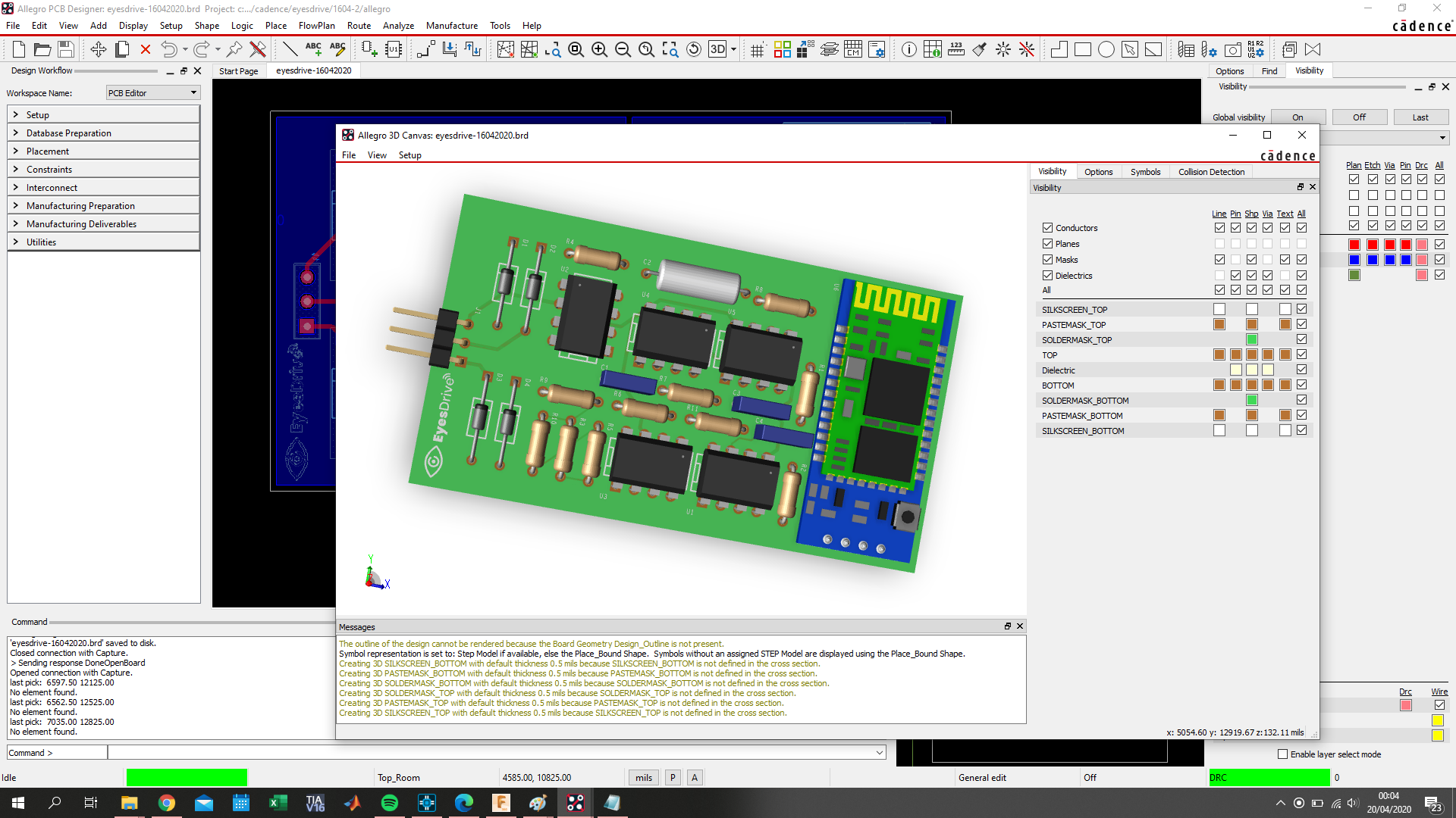
The last revision is now functional in breadboard, the reference voltage is correct and the last stage amplifer works flawlessly, I've also changed the filters, the first and second revisions had only an HPF to block dc and a first order LPF, the last revision has 2 HPF (first order) and a second order LPF. I didn't add a notch filtered at 50 Hz because the EOG signal has a bandwidth of about 10 Hz starting from DC, i just set the cutoff frequency of the LPF around that frequency.
![]()
![]()
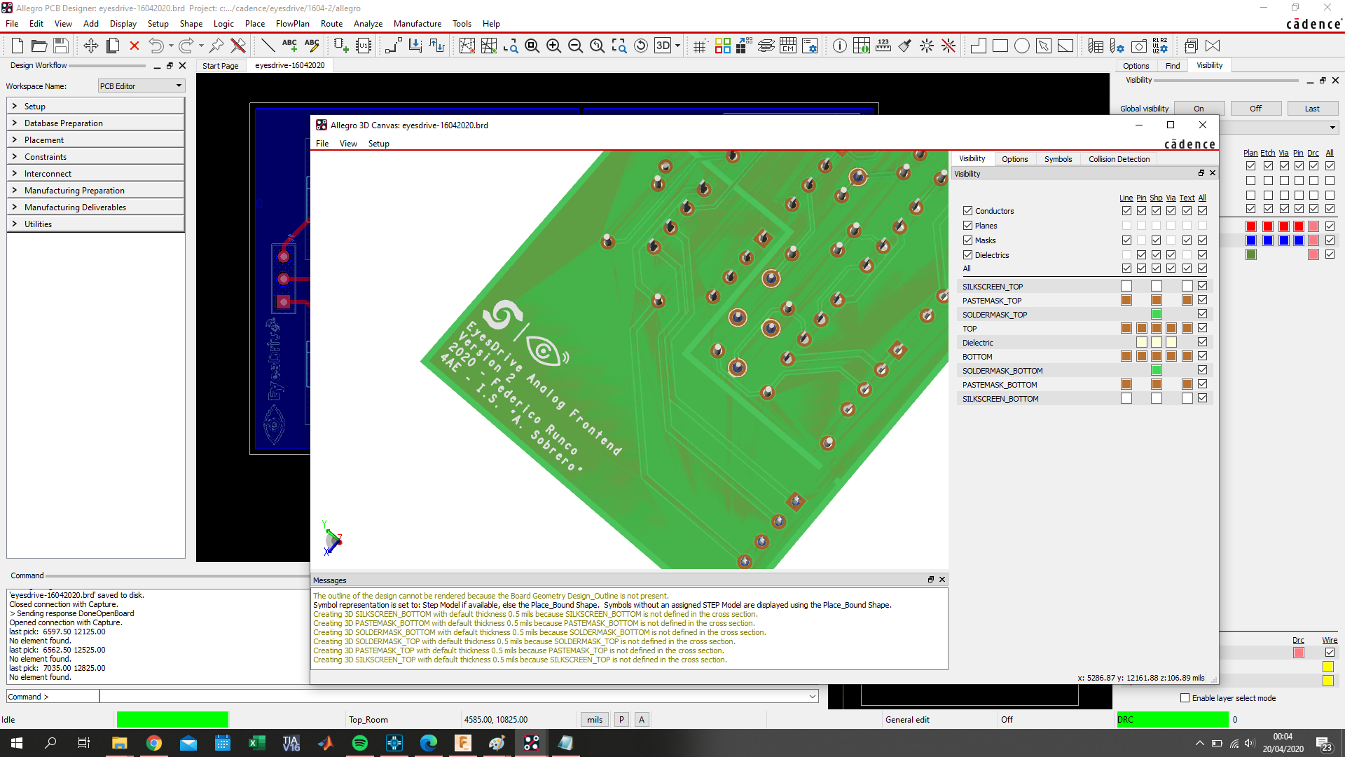
The completed board 3D rendering, actually isn't very beautiful, the traces overlap with the soldermask (but way better than the 3D Canvas of the 17.2 release, that was terrifying), I'll redo a Fusion 360 rendering later
I'm ordering the PCB from JLCPCB as usual, hoping that arrives in time with this pandemic, it is such an horrible situation...
-
The EyesDrive PCB is on its way!
08/18/2019 at 20:17 • 0 commentsAnd after about 16 not working prototypes made in the past 6 months, I can officially say that this revision of the circuit is the right one, also because it's the only one that worked for 30 min straight without any calibration for about 7 days consecutive. Currently, the frontend can only distinguish between left, center and right position, no blink detection yet.
To fully test the whole project I made a little (and also my first) script in Python to simulate the computer arrow keys and I've played some random driving games on the internet. In the beginning, it was quite strange, but after a while, it felt almost natural.
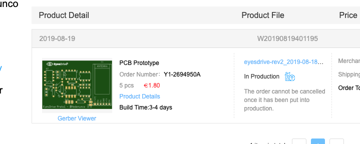
The last thing I haven't made was a PCB so, after designing it in Eagle (no KiCad, sorry, it's quite hard to understand for me), and I've purchased a prototype PCB from JLCPCB.![]()
What surprised me about JLCPCB is the price: it's really cheap, I paid 2 dollars without any shipping fee for 5 boards, that's incredible!
I will probably make a video of the frontend working when the PCB arrives, also because will be in the same period when school begins, then I can also show you some cool waveforms on the oscilloscope.
-
Welcome to the world, analog frontend!
08/12/2019 at 17:29 • 0 commentsSo yes, hopefully, the analog frontend is finally completed! Aside from minor modifications (like better opamps, not that shitty 741), the design has been completed. As you can see in the screenshot down here, eye position and blink are both recognizable. The last step is to process the signal in the Arduino. Eye position processing is quite easy, but blinking recognition will be a challenging quest.
![]()
-
AC coupling. That unknown thing
08/08/2019 at 20:50 • 0 commentsIn the last days I've finally decided to go to the "nearest" (about 15km far) electronics shop to get the missing components. While I've got almost all passives values wrong, they've not affected as much the results.
The good thing is that, after days spent thinking why the signal wasn't centered at my reference voltage, I realized I didn't AC coupled the in-amp: electrodes are adding some DC offset to the signal, and a high pass filter will not filter the whole DC out.
So I opened LTSpice and redesigned the preamp stage, here's the result (blue signal is the original one, with an offset of 50mA circa):

Preamp transient analysis After redesigning the whole preamp stage, the signal is centered at around 2.5V, and now I only need to filter out the signal to complete the design.
I'm also considering to buy an oscilloscope, probably with it I would have seen the DC offset times ago with the FFT (the LabVIEW FFT is crap) and considered the AC coupling, but nowadays DSO are quite expensive.
Here's a recording with the actual circuit, and yes, I'm using an Arduino as a myDAQ, also these things are quite expensive.Only the preamp (that is the circuit on the breadboard) uses 3 op-amps without filtering. I don't know how many IC will be used in the completed board.
![]()
-
Hello there.
08/02/2019 at 10:28 • 0 commentsThat's my first time using hackaday.io for a project of mine. I usually used it to see all those fantastic projects in there.
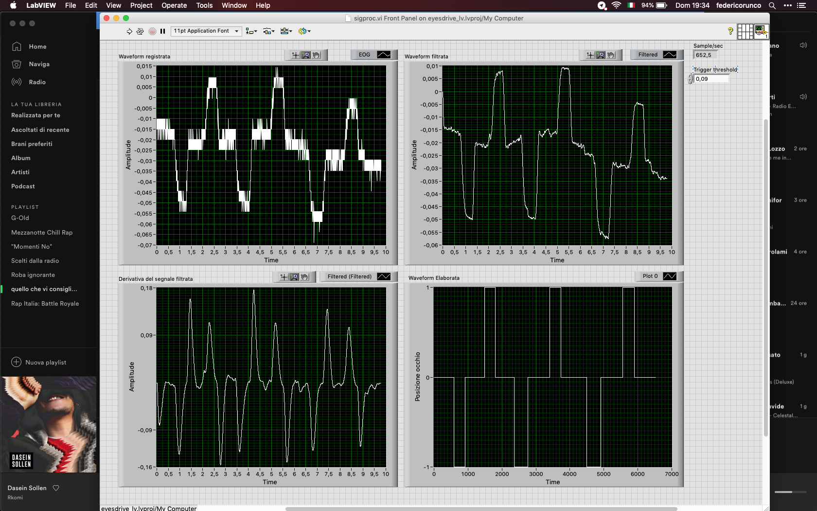
About EyesDrive, the signal conditioning circuitry is almost complete. I'm designing the last stages with LabVIEW (at least nothing will take fire if I simulate things, or am I wrong?). I'm currently trying to deal with that baseline drift that affects my signal. I don't know if it's made by those crap electrodes or by some "strange-biological-process" in my body that's drifting my signal.
The simulated stage seems to be working, but the signal is almost unrecognizable, and I don't know if it will work in a long time.
Here's a screenshot of the LabVIEW VI: the last graph shows the processed signal, the first graph shows the raw signal captured in a 20-sec span.
![]()
EyesDrive - Steering with eyes movement
An innovative, non-invasive, assistive Human Interface Device for ALS affected people based upon Electrooculography (EOG) technique.