-
Testing with 7 Segment Display Code
08/25/2019 at 03:41 • 4 commentsA 4 digit seven segment display is included in the kit. Each segment in the display module is multiplexed, meaning it shares the same anode connection points. And each of the four digits in the module have their own common cathode connection point. This allows each digit to be turned on or off independently. Also, this multiplexing technique turns the massive amount of microcontroller pins necessary to control a display into just eleven or twelve (in place of thirty-two)!
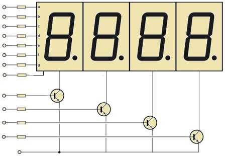
The LED segments of the display require current-limiting resistors when powered from a 5 V logic pin. The value of the resistor is typically between 220 and 470 ohms. And, driver transistors are recommended to provide additional driving current to the LED segments, because each pin of a microcontroller can source or sink near 40 mA of current only. When all (seven) segments of the display turned on at once (the numeral 8), the current demand will exceed this 40 mA limit. The image shown below indicates the basic wiring diagram of the current limiting resistors and driver transistors.
![]()
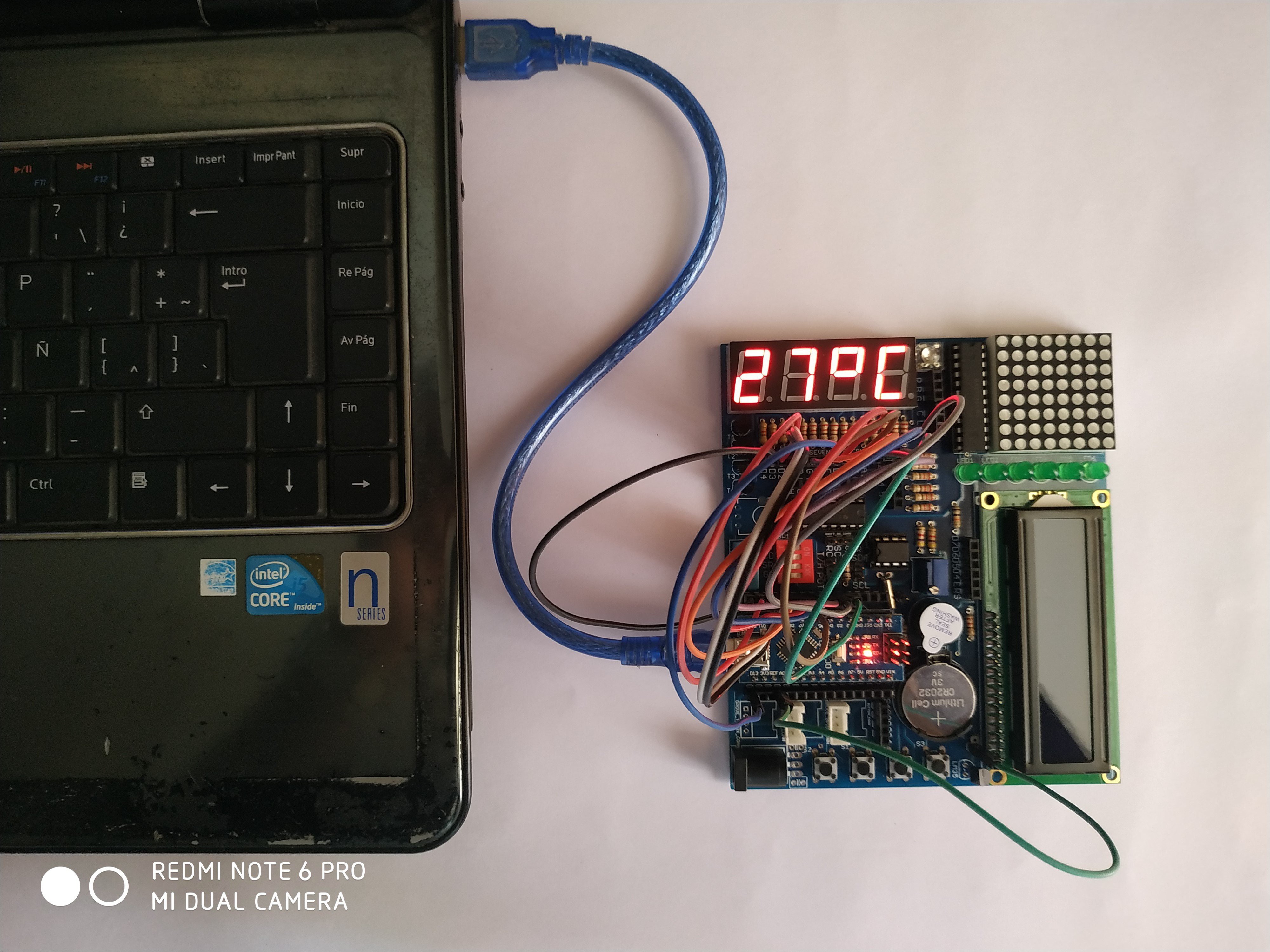
All the above connections are made in the board. You just need to connect 4 digit pins and 7 segment pins to the Arduino digital pin followed by the Arduino sketch. Carefully follow the hookup diagram to complete your hardware, and then upload the sketch to Arduino using the Arduino IDE as usual. The finished circuit can display the temperature using on-board LM35 temperature sensor. Arduino analog pin A0 should be connected to the signal out of the sensor.
//the pins of 4-digit 7-segment display attach to pin2-13 respectively
int a = 2;
int b = 3;
int c = 4;
int d = 5;
int e = 6;
int f = 7;
int g = 8;
int p = 13;
int d4 = 12;
int d3 = 11;
int d2 = 10;
int d1 = 9;

void setup()
{
  //set all the pins of the LED display as output
  pinMode(d1, OUTPUT);
  pinMode(d2, OUTPUT);
  pinMode(d3, OUTPUT);
  pinMode(d4, OUTPUT);
  pinMode(a, OUTPUT);
  pinMode(b, OUTPUT);
  pinMode(c, OUTPUT);
  pinMode(d, OUTPUT);
  pinMode(e, OUTPUT);
  pinMode(f, OUTPUT);
  pinMode(g, OUTPUT);
  pinMode(p, OUTPUT);

}
int del = 5;
int temp;
/***************************************/
void loop()
  temp = analogRead(A0)*500/1023;
{
  clearLEDs();//clear the 7-segment display screen
  pickDigit(0);//Light up 7-segment display d1
  pickNumber((temp/1000));// get the value of thousand
  delay(del);//delay 5ms

  clearLEDs();//clear the 7-segment display screen
  pickDigit(1);//Light up 7-segment display d2
  pickNumber((temp%1000/10));
  delay(del);//delay 5ms

  clearLEDs();//clear the 7-segment display screen
  pickDigit(2);//Light up 7-segment display d3
  //pickNumber(n%100/10);//get the value of ten
  deg();
  delay(del);//delay 5ms

  clearLEDs();//clear the 7-segment display screen
  pickDigit(3);//Light up 7-segment display d4
  //pickNumber(n%10);//Get the value of single digit
  ce();
  delay(del);//delay 5ms
}
/**************************************/
void pickDigit(int x) //light up a 7-segment display
{
  //The 7-segment LED display is a common-cathode one. So also use digitalWrite to  set d1 as high and the LED will go out
  digitalWrite(d1, LOW);
  digitalWrite(d2, LOW);
  digitalWrite(d3, LOW);
  digitalWrite(d4, LOW);

  switch(x)
  {
    case 0:
    digitalWrite(d1, HIGH);//Light d1 up
    break;
    case 1:
    digitalWrite(d2, HIGH); //Light d2 up
    break;
    case 2:
    digitalWrite(d3, HIGH); //Light d3 up
    break;
    default:
    digitalWrite(d4, HIGH); //Light d4 up
    break;
  }
}
//The function is to control the 7-segment LED display to display numbers. Here x is the number to be displayed. It is an integer from 0 to 9
void pickNumber(int x)
{
  switch(x)
  {
    default:
    zero();
    break;
    case 1:
    one();
    break;
    case 2:
    two();
    break;
    case 3:
    three();
    break;
    case 4:
    four();
    break;
    case 5:
    five();
    break;
    case 6:
    six();
    break;
    case 7:
    seven();
    break;
    case 8:
    eight();
    break;
    case 9:
    nine();
    break;
  }
}
void clearLEDs() //clear the 7-segment display screen
{
  digitalWrite(a, LOW);
  digitalWrite(b, LOW);
  digitalWrite(c, LOW);
  digitalWrite(d, LOW);
  digitalWrite(e, LOW);
  digitalWrite(f, LOW);
  digitalWrite(g, LOW);
  digitalWrite(p, LOW);
}

void zero() //the 7-segment led display 0
{
  digitalWrite(a, HIGH);
  digitalWrite(b, HIGH);
  digitalWrite(c, HIGH);
  digitalWrite(d, HIGH);
  digitalWrite(e, HIGH);
  digitalWrite(f, HIGH);
  digitalWrite(g, LOW);
}

void one() //the 7-segment led display 1
{
  digitalWrite(a, LOW);
  digitalWrite(b, HIGH);
  digitalWrite(c, HIGH);
  digitalWrite(d, LOW);
  digitalWrite(e, LOW);
  digitalWrite(f, LOW);
  digitalWrite(g, LOW);
}

void two() //the 7-segment led display 2
{
  digitalWrite(a, HIGH);
  digitalWrite(b, HIGH);
  digitalWrite(c, LOW);
  digitalWrite(d, HIGH);
  digitalWrite(e, HIGH);
  digitalWrite(f, LOW);
  digitalWrite(g, HIGH);
}
void three() //the 7-segment led display 3
{
  digitalWrite(a, HIGH);
  digitalWrite(b, HIGH);
  digitalWrite(c, HIGH);
  digitalWrite(d, HIGH);
  digitalWrite(e, LOW);
  digitalWrite(f, LOW);
  digitalWrite(g, HIGH);
}

void four() //the 7-segment led display 4
{
  digitalWrite(a, LOW);
  digitalWrite(b, HIGH);
  digitalWrite(c, HIGH);
  digitalWrite(d, LOW);
  digitalWrite(e, LOW);
  digitalWrite(f, HIGH);
  digitalWrite(g, HIGH);
}

void five() //the 7-segment led display 5
{
  digitalWrite(a, HIGH);
  digitalWrite(b, LOW);
  digitalWrite(c, HIGH);
  digitalWrite(d, HIGH);
  digitalWrite(e, LOW);
  digitalWrite(f, HIGH);
  digitalWrite(g, HIGH);
}

void six() //the 7-segment led display 6
{
  digitalWrite(a, HIGH);
  digitalWrite(b, LOW);
  digitalWrite(c, HIGH);
  digitalWrite(d, HIGH);
  digitalWrite(e, HIGH);
  digitalWrite(f, HIGH);
  digitalWrite(g, HIGH);
}

void seven() //the 7-segment led display 7
{
  digitalWrite(a, HIGH);
  digitalWrite(b, HIGH);
  digitalWrite(c, HIGH);
  digitalWrite(d, LOW);
  digitalWrite(e, LOW);
  digitalWrite(f, LOW);
  digitalWrite(g, LOW);
}

void eight() //the 7-segment led display 8
{
  digitalWrite(a, HIGH);
  digitalWrite(b, HIGH);
  digitalWrite(c, HIGH);
  digitalWrite(d, HIGH);
  digitalWrite(e, HIGH);
  digitalWrite(f, HIGH);
  digitalWrite(g, HIGH);
}

void nine() //the 7-segment led display 9
{
  digitalWrite(a, HIGH);
  digitalWrite(b, HIGH);
  digitalWrite(c, HIGH);
  digitalWrite(d, HIGH);
  digitalWrite(e, LOW);
  digitalWrite(f, HIGH);
  digitalWrite(g, HIGH);
}

void deg() //the 7-segment led display 9
{
  digitalWrite(a, HIGH);
  digitalWrite(b, HIGH);
  digitalWrite(c, LOW);
  digitalWrite(d, LOW);
  digitalWrite(e, LOW);
  digitalWrite(f, HIGH);
  digitalWrite(g, HIGH);
}

void ce() //the 7-segment led display 9
{
  digitalWrite(a, HIGH);
  digitalWrite(b, LOW);
  digitalWrite(c, LOW);
  digitalWrite(d, HIGH);
  digitalWrite(e, HIGH);
  digitalWrite(f, HIGH);
  digitalWrite(g, LOW);
}
/*******************************************/
You will get the following result if everything goes well.
![]()
-
Testing with 8X8 Dot Matrix code
08/23/2019 at 19:23 • 0 commentsThe kit includes a 8x8 LED matrix. The LED Matrix is connected using the MAX7219 driver. The MAX7219 driver IC is capable of driving 64 individual LEDs while using only 3 wires for communication with the Arduino, and what’s more we can daisy chain multiple drivers and matrixes and still use the same 3 wires.
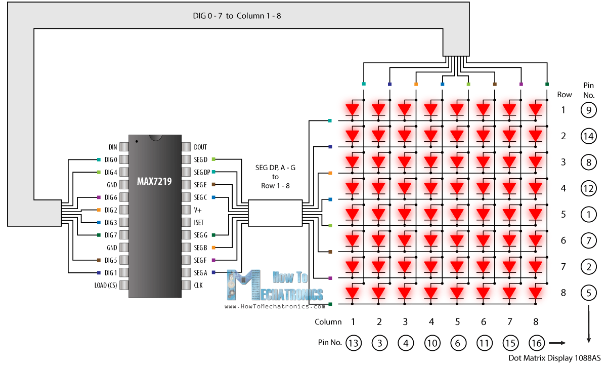
The 64 LEDs are driven by 16 output pins of the IC. The question now is how is that possible. Well the maximum number of LEDs light up at the same time is actually eight. The LEDs are arranged as 8×8 set of rows and columns. So the MAX7219 activates each column for a very short period of time and at the same time it also drives each row. So by rapidly switching through the columns and rows the human eye will only notice a continuous light.
![]()
Note how the pins of a common 8×8 LED Matrix are internally arranged, so if you are building a matrix on your own you should consider it. Also note that a common breakout board for the MAX7219 comes with a resistor between the 5V and the IC pin number 18. The resistor is used for setting the brightness or the current flow to the LEDs.
The VCC and GND of the module go to the 5V and GND pins of the Arduino which are already made and the three other pins, DIN, CLK and CS go to any digital pin of the Arduino board.
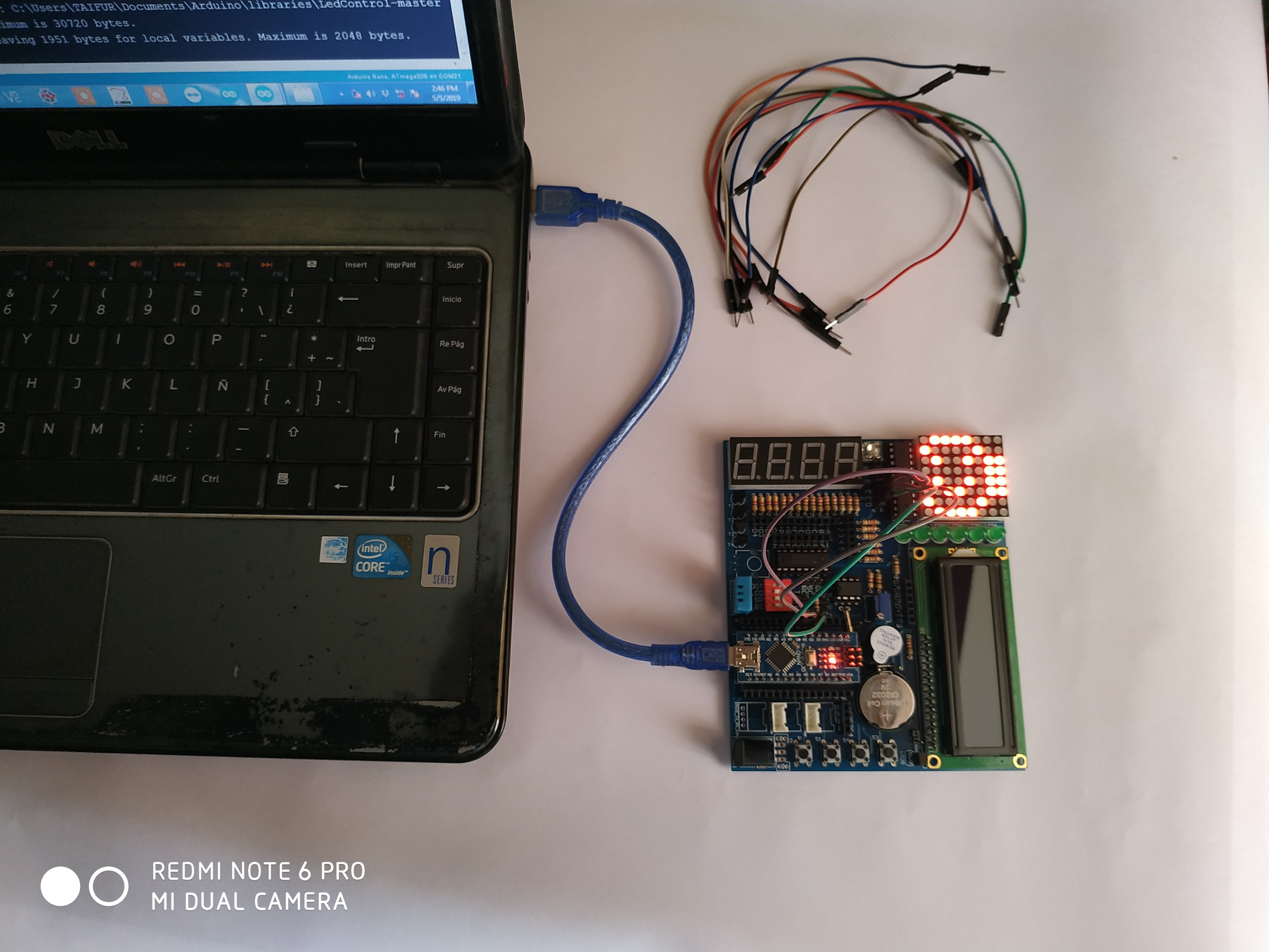
#include "LedControl.h" #include "binary.h" /* DIN connects to pin 12 CLK connects to pin 11 CS connects to pin 10 */ LedControl lc=LedControl(12,11,10,1); // delay time between faces unsigned long delaytime=1000; // happy face byte hf[8]= {B00111100,B01000010,B10100101,B10000001,B10100101,B10011001,B01000010,B00111100}; // neutral face byte nf[8]={B00111100, B01000010,B10100101,B10000001,B10111101,B10000001,B01000010,B00111100}; // sad face byte sf[8]= {B00111100,B01000010,B10100101,B10000001,B10011001,B10100101,B01000010,B00111100}; void setup() { lc.shutdown(0,false); // Set brightness to a medium value lc.setIntensity(0,8); // Clear the display lc.clearDisplay(0); } void drawFaces(){ // Display sad face lc.setRow(0,0,sf[0]); lc.setRow(0,1,sf[1]); lc.setRow(0,2,sf[2]); lc.setRow(0,3,sf[3]); lc.setRow(0,4,sf[4]); lc.setRow(0,5,sf[5]); lc.setRow(0,6,sf[6]); lc.setRow(0,7,sf[7]); delay(delaytime); // Display neutral face lc.setRow(0,0,nf[0]); lc.setRow(0,1,nf[1]); lc.setRow(0,2,nf[2]); lc.setRow(0,3,nf[3]); lc.setRow(0,4,nf[4]); lc.setRow(0,5,nf[5]); lc.setRow(0,6,nf[6]); lc.setRow(0,7,nf[7]); delay(delaytime); // Display happy face lc.setRow(0,0,hf[0]); lc.setRow(0,1,hf[1]); lc.setRow(0,2,hf[2]); lc.setRow(0,3,hf[3]); lc.setRow(0,4,hf[4]); lc.setRow(0,5,hf[5]); lc.setRow(0,6,hf[6]); lc.setRow(0,7,hf[7]); delay(delaytime); } void loop(){ drawFaces(); }![]()
-
Testing with LCD code
08/23/2019 at 18:47 • 0 commentsIn this part, I’ll explain how to connect and program an LCD using the board. The display used in the kit is a 16×2 LCD display. You may be wondering why it’s called a 16×2 LCD. The part 16×2 means that the LCD has 2 lines, and can display 16 characters per line. Therefore, a 16×2 LCD screen can display up to 32 characters at once. It is possible to display more than 32 characters with scrolling though.
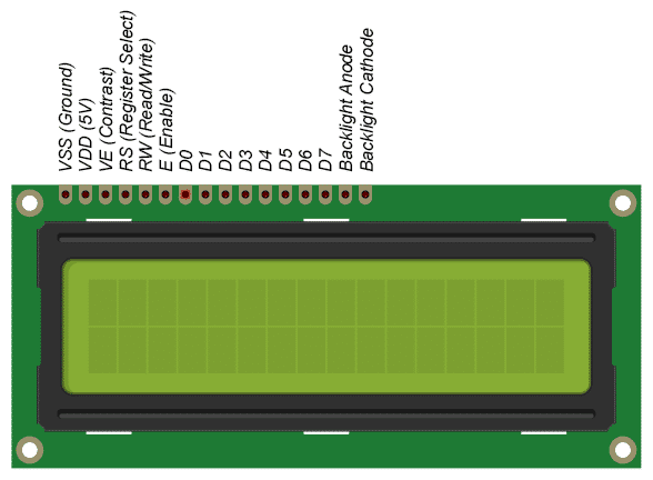
The LCD’s integrated in the kit uses the standard Hitachi HD44780 driver. These displays can be wired in either 4 bit mode or 8 bit mode. Wiring the LCD in 4 bit mode is usually preferred since it uses four less wires than 8 bit mode and the kit has only 4 bit mode option. In practice, there isn’t a noticeable difference in performance between the two modes.
![]()
There is some basic and common connection for LCD which are already made in the kit. You only need to connect 6 pins of LCD to 6 digital pins of the Arduino. These pins are:
- RS (Register Select)
- E (Enable)
- D4-D7 (Data Bus)
Connect this 6 pins to 6 digital pins of Arduino and upload the following code by changing the pin configuration according to your connection:
/*
  LiquidCrystal Library - display() and noDisplay()

 Demonstrates the use a 16x2 LCD display.  The LiquidCrystal
 library works with all LCD displays that are compatible with the
 Hitachi HD44780 driver. There are many of them out there, and you
 can usually tell them by the 16-pin interface.

 This sketch prints "Hello World!" to the LCD and uses the
 display() and noDisplay() functions to turn on and off
 the display.

 The circuit:
 * LCD RS pin to digital pin 12
 * LCD Enable pin to digital pin 11
 * LCD D4 pin to digital pin 5
 * LCD D5 pin to digital pin 4
 * LCD D6 pin to digital pin 3
 * LCD D7 pin to digital pin 2
 * LCD R/W pin to ground
 * 10K resistor:
 * ends to +5V and ground
 * wiper to LCD VO pin (pin 3)

 Library originally added 18 Apr 2008
 by David A. Mellis
 library modified 5 Jul 2009
 by Limor Fried (http://www.ladyada.net)
 example added 9 Jul 2009
 by Tom Igoe
 modified 22 Nov 2010
 by Tom Igoe
 modified 7 Nov 2016
 by Arturo Guadalupi

 This example code is in the public domain.

 http://www.arduino.cc/en/Tutorial/LiquidCrystalDisplay

*/

// include the library code:
#include <LiquidCrystal.h>

// initialize the library by associating any needed LCD interface pin
// with the arduino pin number it is connected to
const int rs = 12, en = 11, d4 = 5, d5 = 4, d6 = 3, d7 = 2;
LiquidCrystal lcd(rs, en, d4, d5, d6, d7);

void setup() {
  // set up the LCD's number of columns and rows:
  lcd.begin(16, 2);
  // Print a message to the LCD.
  lcd.print("hello, world!");
}

void loop() {
  // Turn off the display:
  lcd.noDisplay();
  delay(500);
  // Turn on the display:
  lcd.display();
  delay(500);
}
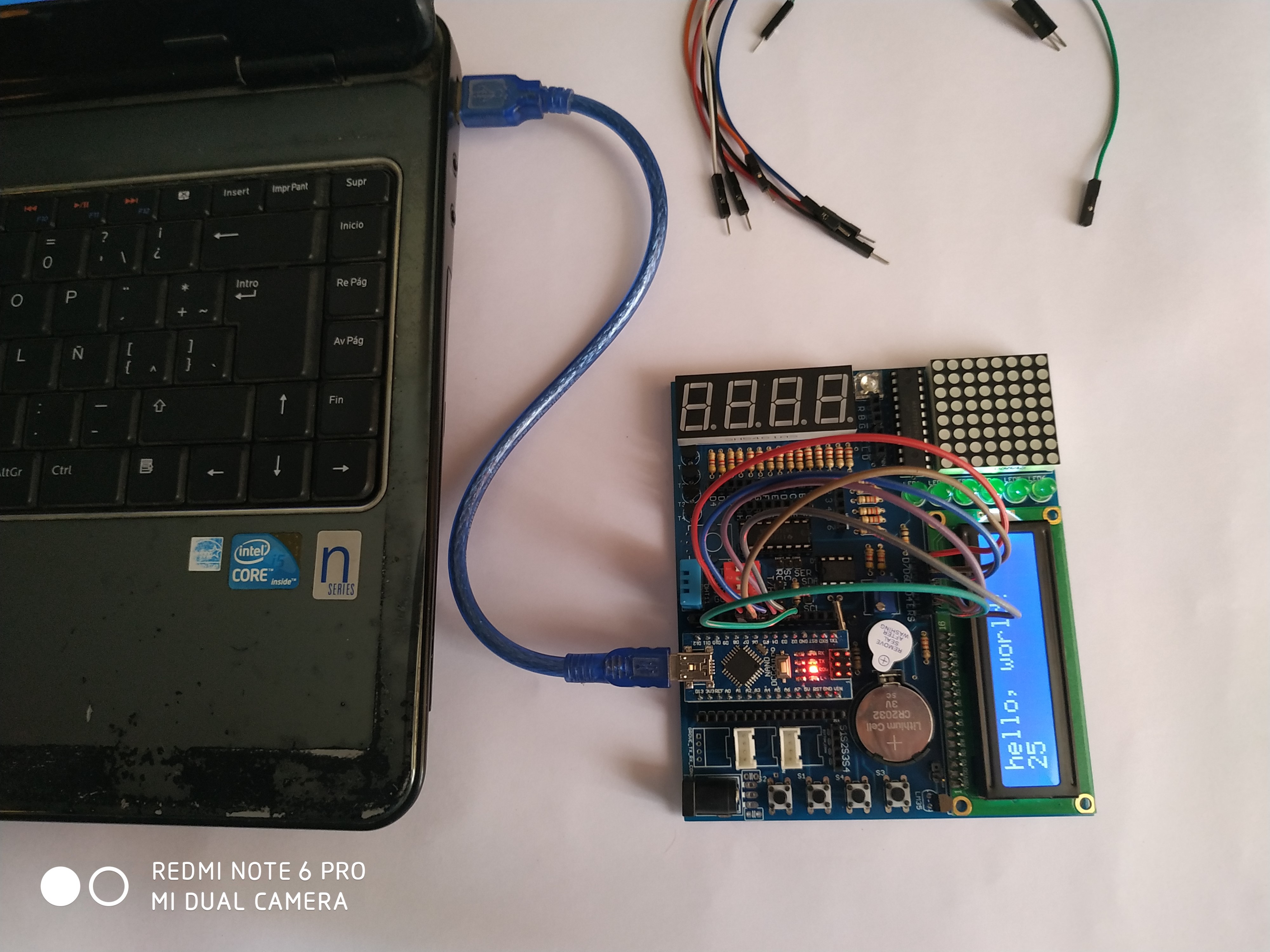
The output on the display:
![]()
Open Source Arduino Learner Kit
This is a hardware development board designed for Arduino beginners. Lots of IO devices are in-built in the board.
 Md. Khairul Alam