Also note: I have ceased active development on this project. Please Don't ask.
Note: this writeup is somewhat out of date, as it doesn't cover many results that I ended up discussing at Supercon 2019. Until I get a chance to update these pages, you can check out the video of my talk:
Here is a link to the slides from the talk [50 MB PDF warning!].
If you are interested in getting involved with this project, please join us in the public chat: https://hackaday.io/messages/room/282439
This project is the culmination of some of the experiments over on #The Rise and Fall of Pulses. It may or may not have been obvious what the goals of that project were, but this scope was one of them. There are a handful of other designs in the pipeline as well at this stage, using various approaches to the GHz+ waveform sampling problem.
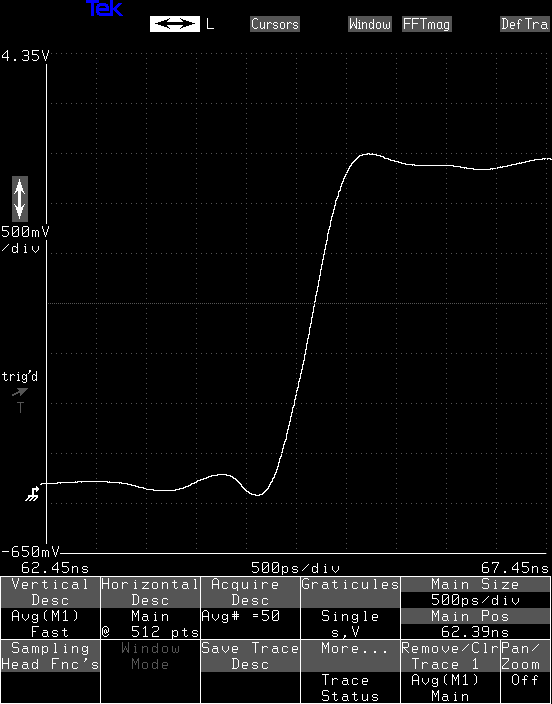
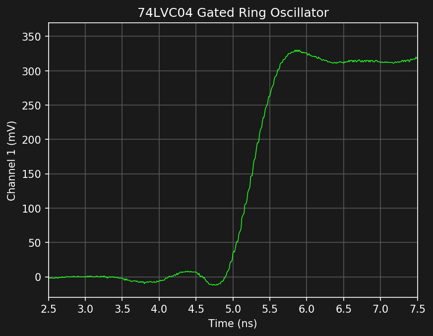
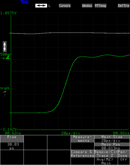
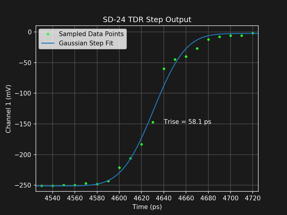
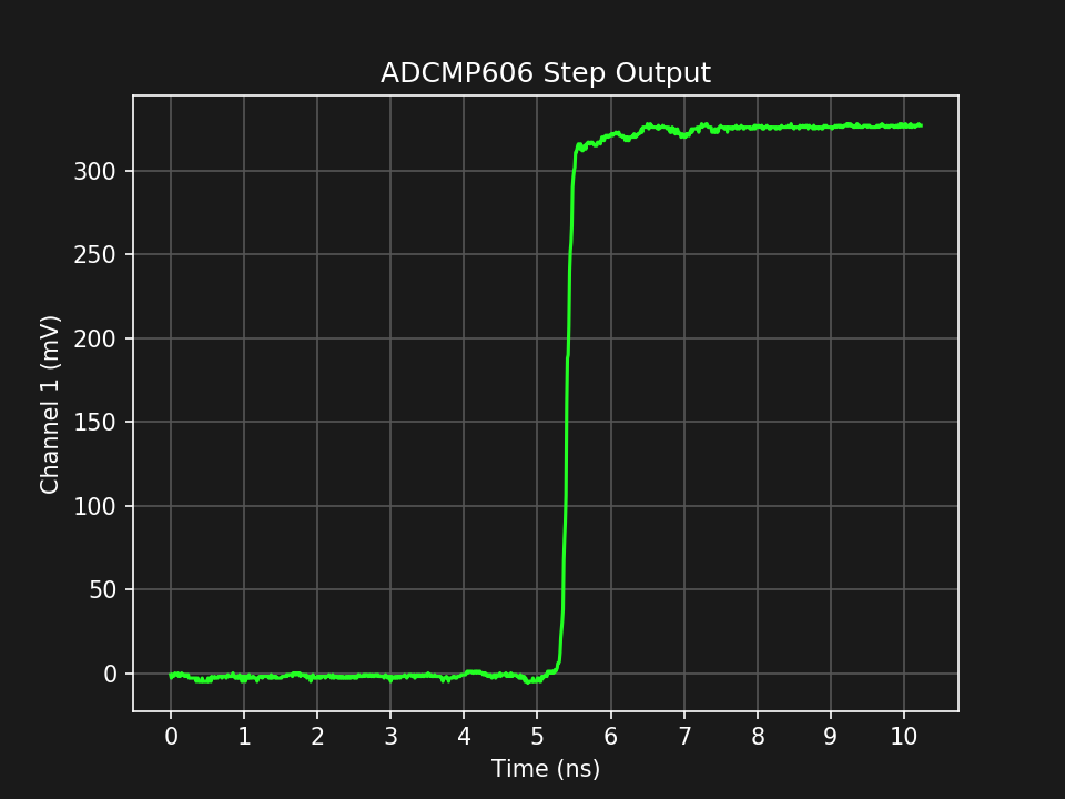
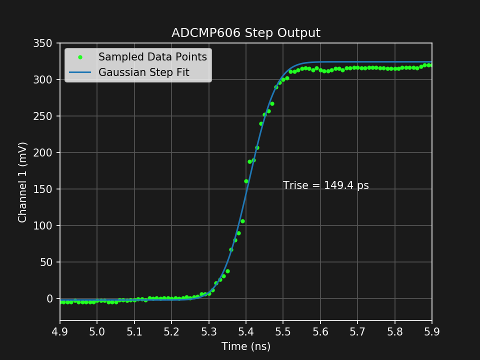
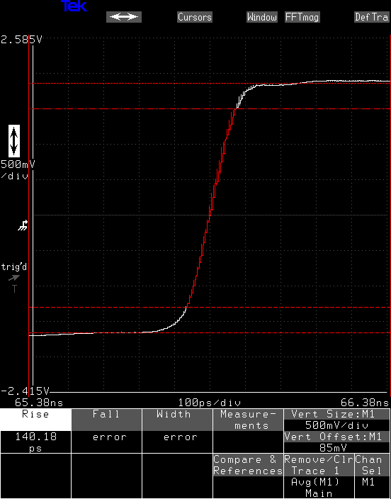
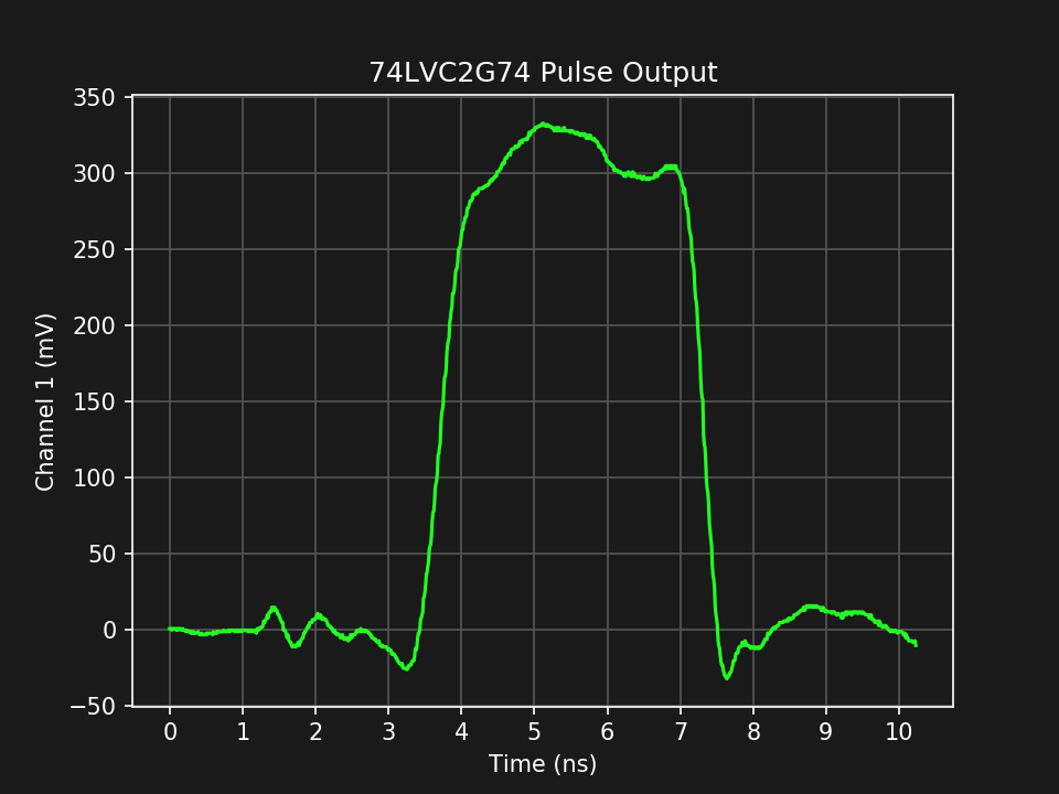
This particular project uses a latched comparator as a voltage sampler, specifically the ADCMP582 from Analog Devices. Built on SiGe, this $20 (single-quantity) comparator has a sampling aperture of 5 ps, and a typical front-end bandwidth of 8 GHz. This ultimately limits the bandwidth of the resulting instrument, but other factors in the current design reduce the system bandwidth into the 6 GHz range. Very preliminary tests estimate the rise time of the scope to between 50 and 70 ps, corresponding to between 7 and 5 GHz bandwidth, respectively. I'm calling it 6 GHz for now, and I expect it can be improved somewhat,
The basic idea is similar to a simple "toy" version I made on the other project with comparators I had on-hand at the time.
This project is a work-in-progress. Specifically, the first prototype that produced these results doesn't have the capability to calibrate its own timebase, which experiences serious drift with temperature. I have a prototype of the timebase calibrator on another PCB, although the two have yet to be integrated. So, it's not a scope you can just build and use quite yet.
Another thing that has yet to be integrated is an extended timebase that would allow you to capture longer sweeps. The first prototype is limited to sweeps of 10 ns, and while this is probably OK for many uses of a 6 GHz sampling oscilloscope, longer sweeps are sometimes very useful.
A word of caution: don't get too excited about this project until you know the difference between a sampling oscilloscope and a real-time oscilloscope: they're vastly different beasts, suited to different purposes, and behave in different ways. The ubiquity of cheap, real-time, (but low-bandwidth) digitizing scopes has created expectations that sampling scopes, or even analog scopes, can't meet. For an introduction, you can check out this article on ElectronicDesign.
As usual, the real information for this project is in the build logs.
It will be open-sourced, but I'm not posting the design files for the first prototype, because it's lacking too many things to be practical. If someone really wants to get a crack at the design files, ping me. The schematic and and board layout are in PDFs in the files section of the project for reference.
 Ted Yapo






 Lucy Fauth
 Mike Kibbel
hello, i know that this project is no longer under development but i was wondering whether the pdf schematic and pdf board layout plus you'r talk are the only available files to this project and whether a board or gerber file exists?