Blecky
-
Screenshots
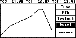
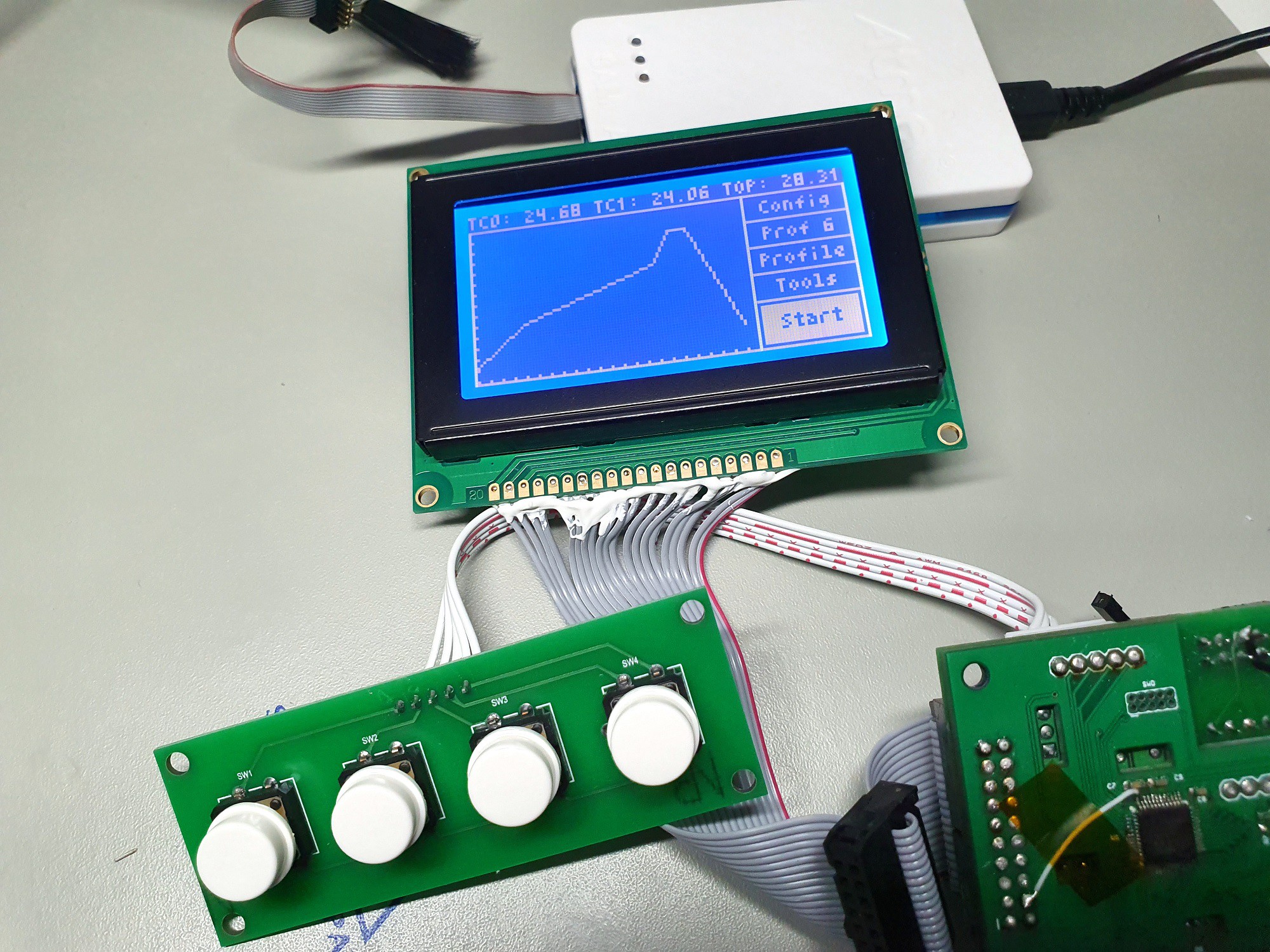
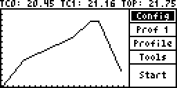
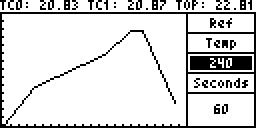
11/18/2019 at 13:49 • 0 commentsThere's now a screenshot command which generates an XBM bitmap over the serial port. Here's a few screenshots for your viewing pleasure. Note the ticks on the profile display, each tick represents 20 degrees (or 5 degrees per pixel) across the Y axis. As for seconds, each tick represents 20 seconds (or 5 seconds per pixel) across the X axis.
Main Screen:
![]() Compare this to the existing display:
Compare this to the existing display:![]() ---------- more ----------
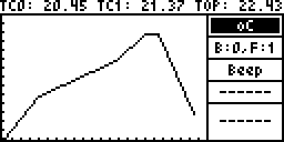
---------- more ----------Config:
![]()
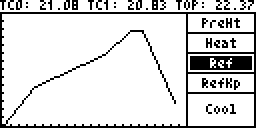
Profile:![]()
Profile Edit:
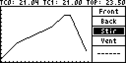
![]() Tools:
Tools:![]()
Test Out:
![]()
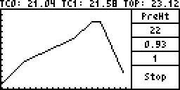
Reflow:
![]()
-
Zero Crossing Tweaks
11/15/2019 at 12:16 • 0 commentsThe mod boards also have a zero crossing detection circuit built in. The detection code is really simple, basically the zero detection pin from the optocoupler is connected to an interrupt line:
attachInterrupt(digitalPinToInterrupt(ZER_D), zeroCrossing, RISING);
And when the interrupt is triggered by the pulses generated by the optocoupler circuit, it changes the output state of the output solid state relays on the board:
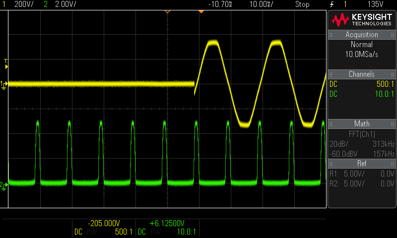
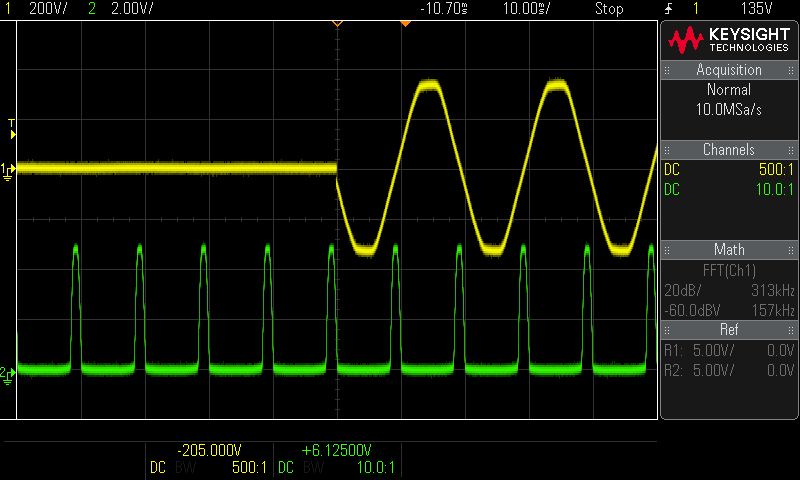
void zeroCrossing()
{
  if (frontState == 1) //Turn on
  {
    digitalWrite(FRONT_HEATER, 0);
  } else { //Turn off
    digitalWrite(FRONT_HEATER, 1);
  }
  if (backState == 1) //Turn on
  {
    digitalWrite(BACK_HEATER, 0);
  } else { //Turn off
    digitalWrite(BACK_HEATER, 1);
  }
  if (convectionState == 1) //Turn on
  {
    digitalWrite(CONVECTION, 0);
  } else { //Turn off
    digitalWrite(CONVECTION, 1);
  }
  if (exhaustState == 1) //Turn on
  {
    digitalWrite(EXHAUST, 0);
  } else { //Turn off
    digitalWrite(EXHAUST, 1);
  }
}
I finally got my hands on a differential probe to actually take some measurements to see how well it was working.
![]() ---------- more ----------
---------- more ----------Oh, so it's firing a bit too soon. It looks like the optocoupler/solid state relay circuit fires the AC line a bit earlier than the expected output. No matter, by the looks of things, we could fire this on the falling edge of the output instead.
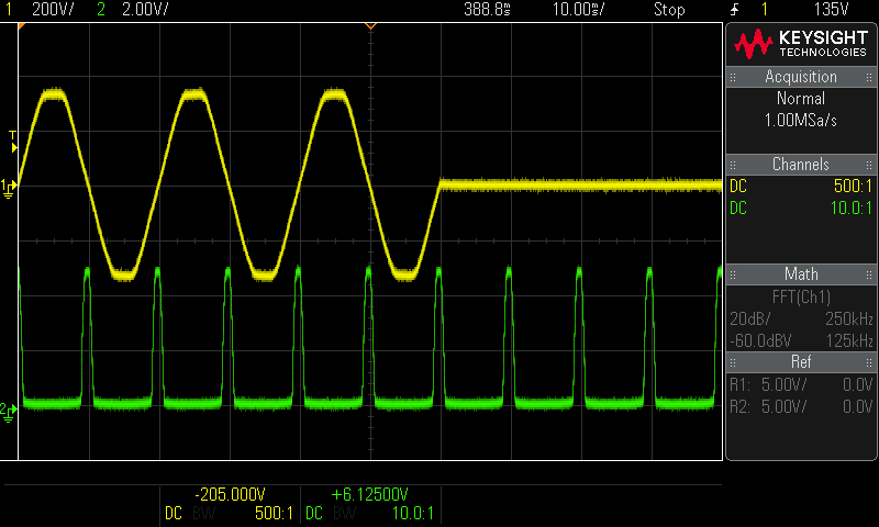
attachInterrupt(digitalPinToInterrupt(ZER_D), zeroCrossing, FALLING);
![]()
That's pretty close to bang on, but still not perfect as the turn off function will be late now (it will have a similar spike to the previous RISING condition). We could put a timer function in there to shift this and deal with both conditions that way, however different mains frequencies will change these timings slightly and require tuning and/or timing code.
Honestly I prefer simplicity, so the other way to deal with different conditions for off and on is to service both rising and falling interrupts to handle the different turn on and turn off states:
attachInterrupt(digitalPinToInterrupt(ZER_D), zeroCrossing, CHANGE);void zeroCrossing() { int state = digitalRead(ZER_D); if (state == 0) //We're in falling { if (frontState == 1) //Turn on { digitalWrite(FRONT_HEATER, 0); } if (backState == 1) //Turn on { digitalWrite(BACK_HEATER, 0); } if (convectionState == 1) //Turn on { digitalWrite(CONVECTION, 0); } if (exhaustState == 1) //Turn on { digitalWrite(EXHAUST, 0); } } else { //We're in rising if (frontState == 0) { //Turn off digitalWrite(FRONT_HEATER, 1); } if (backState == 0) { //Turn off digitalWrite(BACK_HEATER, 1); } if (convectionState == 0) { //Turn off digitalWrite(CONVECTION, 1); } if (exhaustState == 0) { //Turn off digitalWrite(EXHAUST, 1); } } }
Done!![]()
-
Sooo Baked!
11/13/2019 at 11:35 • 0 commentsSo everything is pretty much finished and working now. All the gerbers and firmware are available on the github repo. I also have a limited run on Tindie if anyone is interested - https://www.tindie.com/products/blecky/brtro-420-better-blazin-mod/
There's probably some documentation clean up, but that will more or less come when people ask for it as there's not a huge amount of time to polish that up.
Now onto baking :D
-
Getting Baked Gets You Routed
11/05/2019 at 05:37 • 0 commentsIf you check the update to the previous log entry, the board temps were getting up to 290 degrees Celsius. So after thinking about it for a bit, the thermocouples floating inside the oven are basically next to useless for any sort of temperature regulation as they don't correlate to any meaningful and reproducible temps, no matter the board colour.
Now it's time to replace the thermocouples. The main issue is how to route the thermocouples. Firstly the existing thermocouples are glued into the chassis, so removal is difficult. And secondly, where they come out is a bit tricky from a cable management point of view, since the tray slides in and out (i.e. how are you going to deal with the excess lead and how do you stop it from knocking parts off when you slide it back in).
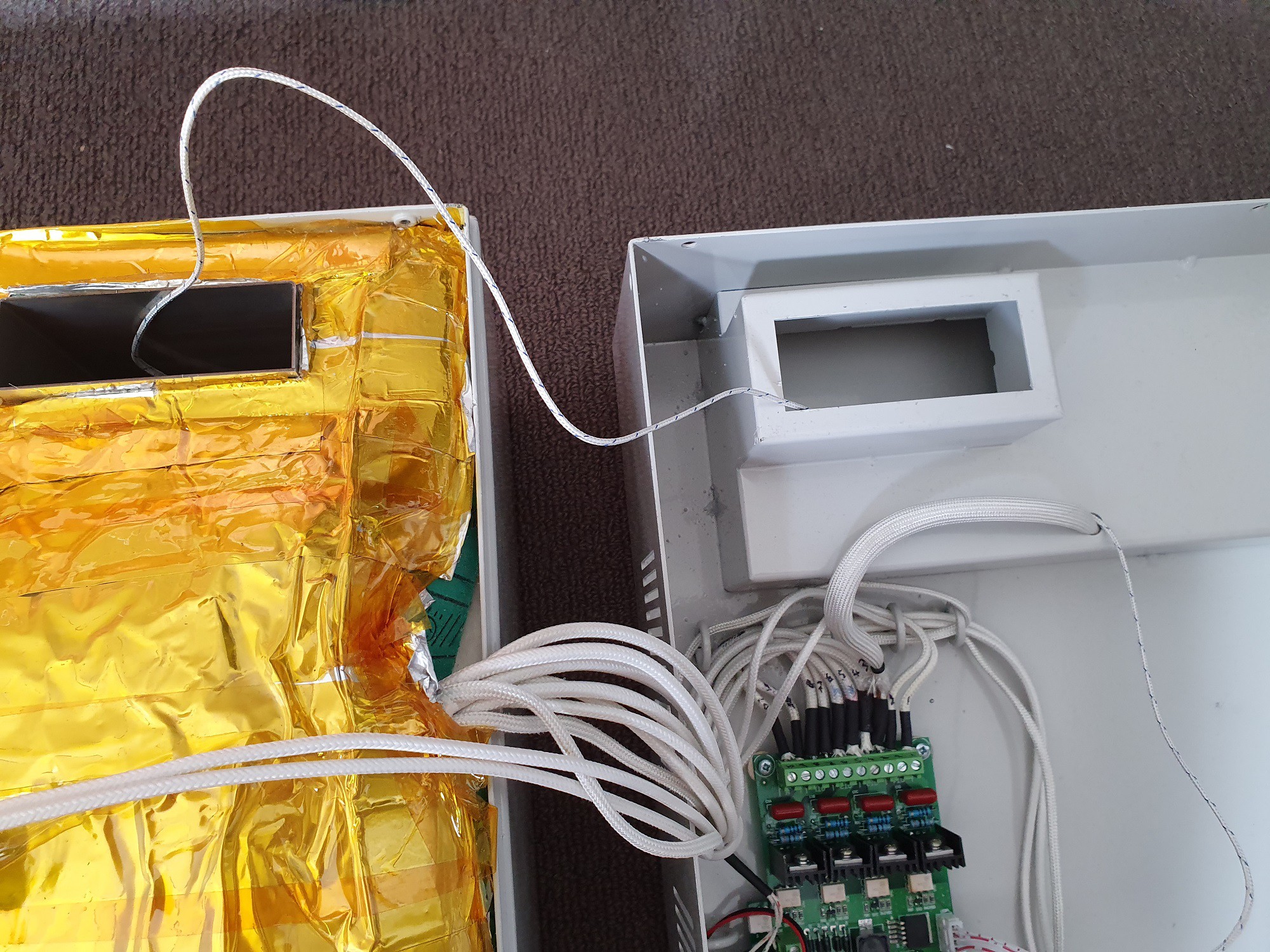
So to deal with this a new route was found. This was actually easy to do without any mods as the forced air extraction system already has a way to go without modifying the case (there's a small hole for entering this section which the power lead for the secondary fan goes through):
![]()
Inside the flue section on the left of the image above, there is some vent holes that go into the case, so you can just feed the thermocouple through those vent holes and you're in. Be careful when putting the case on now so the thermocouple wire doesn't get crushed.
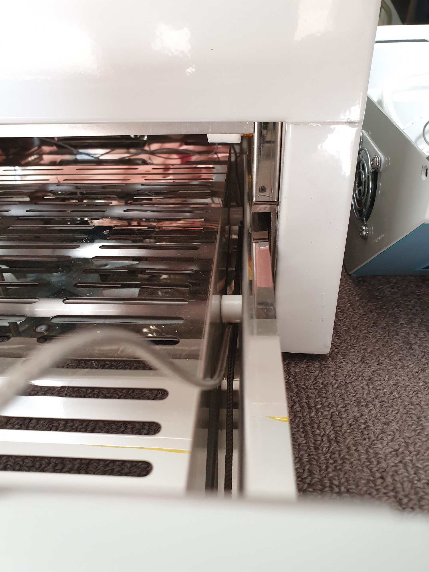
Now inside the case, you can feed the thermocouple on the right side of the tray in the grove and you can tie off the excess with some steel wire such that it moves under the tray when you slide in and out in a concertina fold, leaving just the end piece to worry about when positioning it (i.e. just tape it to the board and you're done).
![]()
With all that done, you can now get an almost perfect thermal profile and it's guaranteed to correspond to the actual board temps. Note I was using two board colours in this test and the graph is drawn based on the average of the two temps.
![]()
We're ready for prime time! -
This Oven is Not Very Blunt
11/03/2019 at 09:55 • 0 commentsThe oven gives you a bunch of informative feedback over serial about its current operation. For example, here's the output from a reflow process:
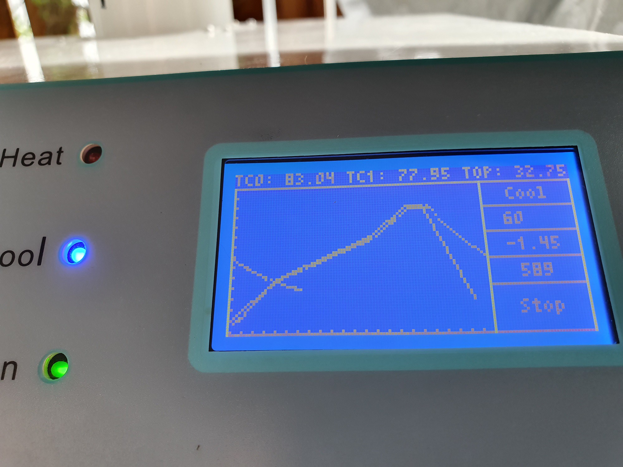
Reflow Started
Profile Settings (1)
PreHt: 100°C, 80s
Heat: 180°C, 220s
Ref: 240°C, 30s
RefKp: 240°C, 30s
Cool: 50°C, 80s

Channel 0 PID Preheat
P: 50.28
I: 4.78
D: 166.72

Channel 1 PID Preheat
P: 96.98
I: 26.96
D: 210.38

Channel 0 PID Heat
P: 97.00
I: 25.97
D: 168.54

Channel 1 PID Heat
P: 44.30
I: 6.56
D: 201.32

Channel 0 PID Reflow
P: 38.12
I: 2.15
D: 200.13

Channel 1 PID Reflow
P: 43.01
I: 6.73
D: 400.31

Mode,Seconds,SetPoint,TC0,RateTC0,PWMOut0,TC1,RateTC1,PWMOut1

PreHt,0,46.09,45.13,223.39,95.79,46.92,232.26,0.00
PreHt,1,46.82,45.00,-0.62,100.00,47.04,1.04,0.00
PreHt,2,47.59,45.00,0.83,91.11,47.17,0.41,18.85
PreHt,3,48.31,45.42,1.45,2.51,47.88,0.62,0.00
....
Heat,83,100.24,99.71,1.04,0.00,100.83,1.04,0.00
Heat,84,100.63,100.62,0.41,30.46,101.62,0.62,0.00
Heat,85,101.04,100.92,0.21,77.28,101.96,-0.21,87.07
Heat,86,101.44,101.17,-0.21,100.00,102.21,-0.62,100.00
....
Ref,304,180.41,179.79,1.24,0.00,179.83,0.83,0.00
Ref,305,182.57,180.25,0.21,100.00,180.75,1.87,0.00
Ref,306,184.85,180.62,0.41,100.00,180.96,-1.24,100.00
Ref,307,187.02,180.58,0.83,100.00,181.25,-0.83,100.00
....
RefKp,403,240.00,238.33,1.04,0.00,238.46,0.62,0.00
RefKp,404,240.00,237.92,-1.66,100.00,236.83,-2.90,100.00
RefKp,405,240.00,236.87,-1.45,100.00,236.87,-0.83,100.00
RefKp,406,240.00,237.46,0.83,30.11,236.21,-1.04,100.00
....
Cool,434,238.44,238.58,-1.24,94.78,239.96,-1.45,100.00
Cool,435,235.88,238.50,0.00,100.00,239.58,0.41,100.00
Cool,436,233.20,237.92,-1.45,100.00,238.71,-1.24,100.00
Cool,437,230.65,234.21,-3.73,100.00,236.87,-3.32,100.00
....
Cool,762,50.00,50.33,0.00,100.00,54.96,-1.66,100.00
Cool,763,50.00,47.71,-2.90,0.00,52.88,-3.32,100.00
Reflow Complete
The LCD display also gives you a nice little overlay of the current reflow process, which shows how well it fit the curve:
![]()
As you can see, while the oven does struggle a little to keep up with the steep ramp rate required in the reflow phase of this profile, it does get relatively close (despite lagging a little). Tweaking the ramp rates of the different stages will yield fitter results.
The graph will overflow to the other side as well (as you can see with the cooling cycle tail).
Edit: something in the back of my mind from the start was the built in thermocouples not getting as hot as the boards themselves, which is a common problem with IR based ovens. This is more extreme that first thought as a black test PCB got up to 290oC during the reflow phase. As I feared, we are going to have to either create different modes for different PCB colours, or move/swap out the thermocouples to have them contact the boards.
This is tricky, since we have a tray that slides in and out and there are two thermocouples for each zone. Maybe a third thermocouple is required to offset the actual temps (using the built in ones to control PID rates for each zone)? Maybe we can have fixed metal plate that we can permanently have thermocouples attached to on the tray. I think moving to thermocouples on the board is the way to go however as it removes a lot of the guess work.
-
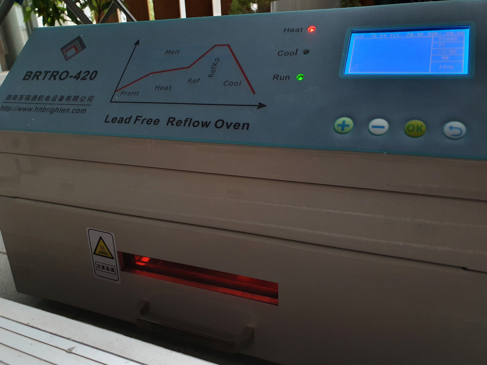
This Oven Has Flow
11/03/2019 at 05:52 • 0 comments![]()
So the firmware is pretty much complete apart from some more tuning to do. I've created a quick video showing the operation below (apologies for the LCD quality, the sun was out and the light polarisation gets a bit screwy, but you get the idea).
You might notice that it struggles slightly to keep up with an aggressive profile, but the oven doesn't change to the next state until both the minimum current profile stage time and temps are met, to ensure an adequate reflow. This is waaay better than the stock firmware, which would just continue after the profile phase was meant to be up (based on its configuration). So depending on the initial start temp and the amount of effort you were willing to put into configuring the profiles, would end up with many failed reflows on the stock firmware.
This is actually quite a misunderstood issue with a lot of reflow oven firmware out there. Most of the time it's attributed to needing to run an initial reflow cycle to bring the oven up to temperature first, but in the earlier, less critical stages where it might need to catch up from a lower room temp, strict adherence to the profile is less important, especially if below the activation temp of the flux (don't take this as something that should be ignored though). But it is VERY important to get it to the right temp before moving onto the next stages of reflow. It really is in the name of the early stages, "pre-heat" (depending on which nomenclature you are using). We want to use this "pre-heat" stage to "literally" "pre-heat" the oven before moving onto next stages (hopefully that was clear :P).
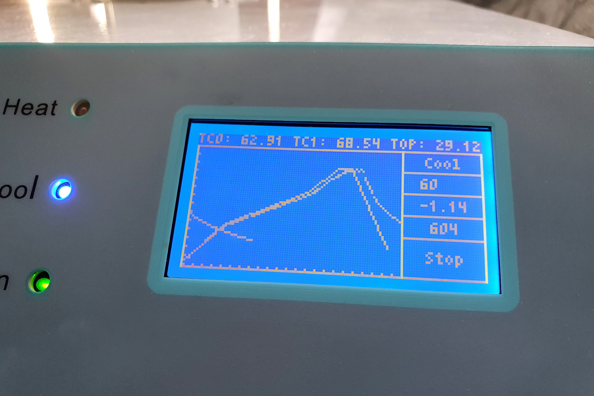
The LCD also draws the current temps over the displayed profile, so you can check its fitness to the curve. Also displayed is the cold junction temp of the thermocouple interface (as Top). This lets you know how hot the controller PCB/top of the chassis gets.
The oven itself has two separate PID loops for both the front and back elements, which coincide with the front and back thermocouples. These do fight slightly if they have different PID parameters, but for the most part they remain pretty steady as the convection fan stirs the air around anyway to keep things even.
The cooling phase still needs to be tweaked to ramp up the initial fan speed also.
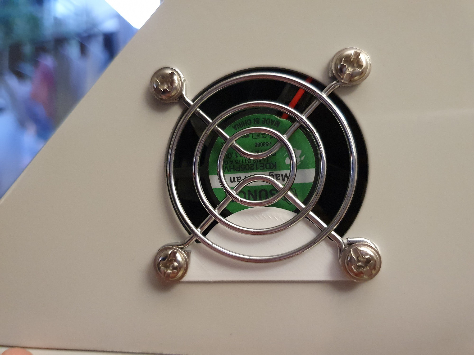
Oh, talking about flow. I've also created a 3D printable shim which reduces case fan noise too:
![]()
It also has an auto tuner for each stage of the reflow process, producing independent (yet interdependent) results for each of the channels:// ***** PRE-HEAT STAGE ***** #define PID_KP_PREHEAT_C0 50.28 #define PID_KI_PREHEAT_C0 4.78 #define PID_KD_PREHEAT_C0 166.72 #define PID_KP_PREHEAT_C1 96.98 #define PID_KI_PREHEAT_C1 26.96 #define PID_KD_PREHEAT_C1 210.38 // ***** SOAKING STAGE ***** #define PID_KP_SOAK_C0 97.00 #define PID_KI_SOAK_C0 25.97 #define PID_KD_SOAK_C0 168.54 #define PID_KP_SOAK_C1 44.30 #define PID_KI_SOAK_C1 6.56 #define PID_KD_SOAK_C1 201.32 // ***** REFLOW STAGE ***** #define PID_KP_REFLOW_C0 38.12 #define PID_KI_REFLOW_C0 2.15 #define PID_KD_REFLOW_C0 200.13 #define PID_KP_REFLOW_C1 43.01 #define PID_KI_REFLOW_C1 6.73 #define PID_KD_REFLOW_C1 400.31It stores these also in the MCU flash as startup parameters, so you don't need to muck about with changing these values.
-
We'll Be Baking Soon
10/12/2019 at 14:49 • 0 commentsAfter ironing out a couple of PCB bugs, things are getting there. A trace got missed on the LCD display and the LEDs won't light up with the current rev of the board without a simple mod. But everything works now without any modifications required to the existing board (apart from putting a jumper on).
One of the buttons (back button) also managed to share the same EXTINT[3] with the zero crossing detection circuit on the SAMC21, so the button is handled separately in the main loop instead (which can cause a missed click every now and then, but it's not that bad).
It also turns out that the original circuitry and power supply was very very noisy, which causes random button presses and other minor undesirable issues like LCD glitches when not redrawing often. The new thermocouples are on their own 3.3V linear regulator, so there isn't much of an issue there. The buttons were fixed by having longer debouncing delays. This goes to show that the original hardware was completely inadequate for the task and the controller should really be replaced from the get go.
Most of the menu functions and profile modification/display features have also been created:
![]()
Now just onto the PID control and timing!
-
It Lives!
10/07/2019 at 13:55 • 0 commentsAfter a bit of mucking about it lives!
![]()
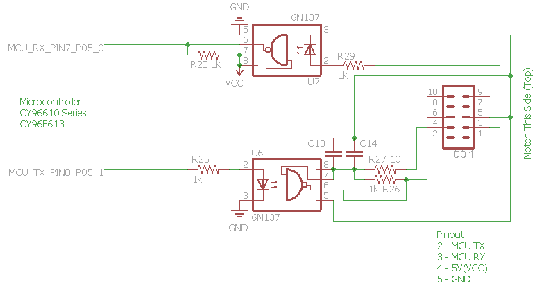
It turns out the optocouplers are wired up in an inverting mode, so the UART doesn't work at all. Here's the original optocoupler (reverse engineered) schematic:![]()
The SAMC21 (nor any of the SAMx2x microcontrollers) doesn't allow you to invert the hardware UART polarity, so you would have a tricky time getting a software UART working if you want to use the Arduino bootloaders (you could forego the bootloader, but where's the fun in that?). Now theoretically, you could use a UART->USB controller that had inverted logic, but most don't seem to.
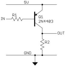
So instead, there was enough free pads around the UART connectors (these were originally put in to be able to change the RX/TX orientation if necessary) to wire in some SOT-23 PNP based inverters while keeping things relatively neat (take note that the transmit LED needs a current limit resistor too otherwise you just get spikes on the UART bits as the LED starts to dim/burn out due to excess current):
![]()
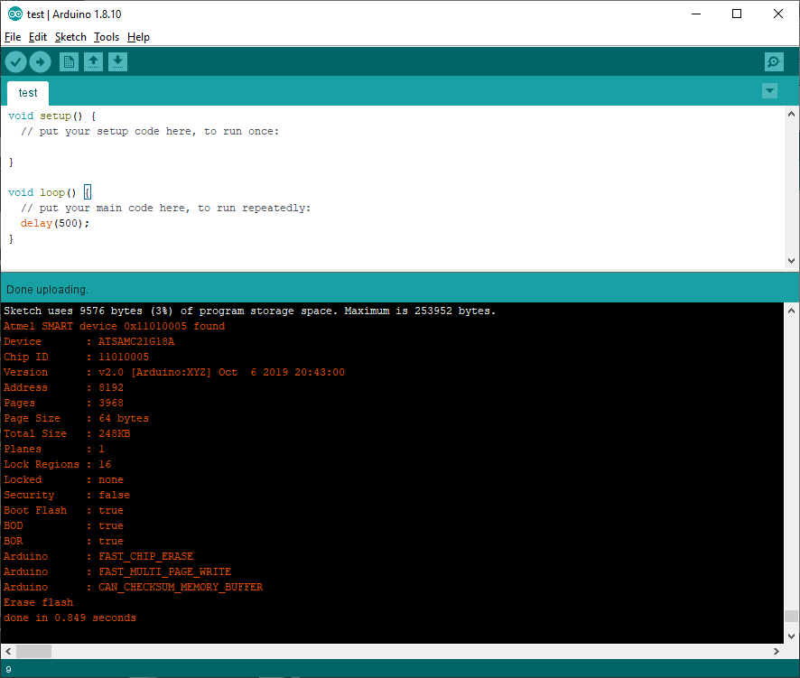
As for the bootloader/core, I'm using a modified mattairtech ArduinoCore-samd (which is a modified ArduinoCore-samd) firmware which has options for the SAMC. The pinouts have changed of course, so a recompile of the bootloader is necessary to get things running.
-
Smoke Up that Primo Mod
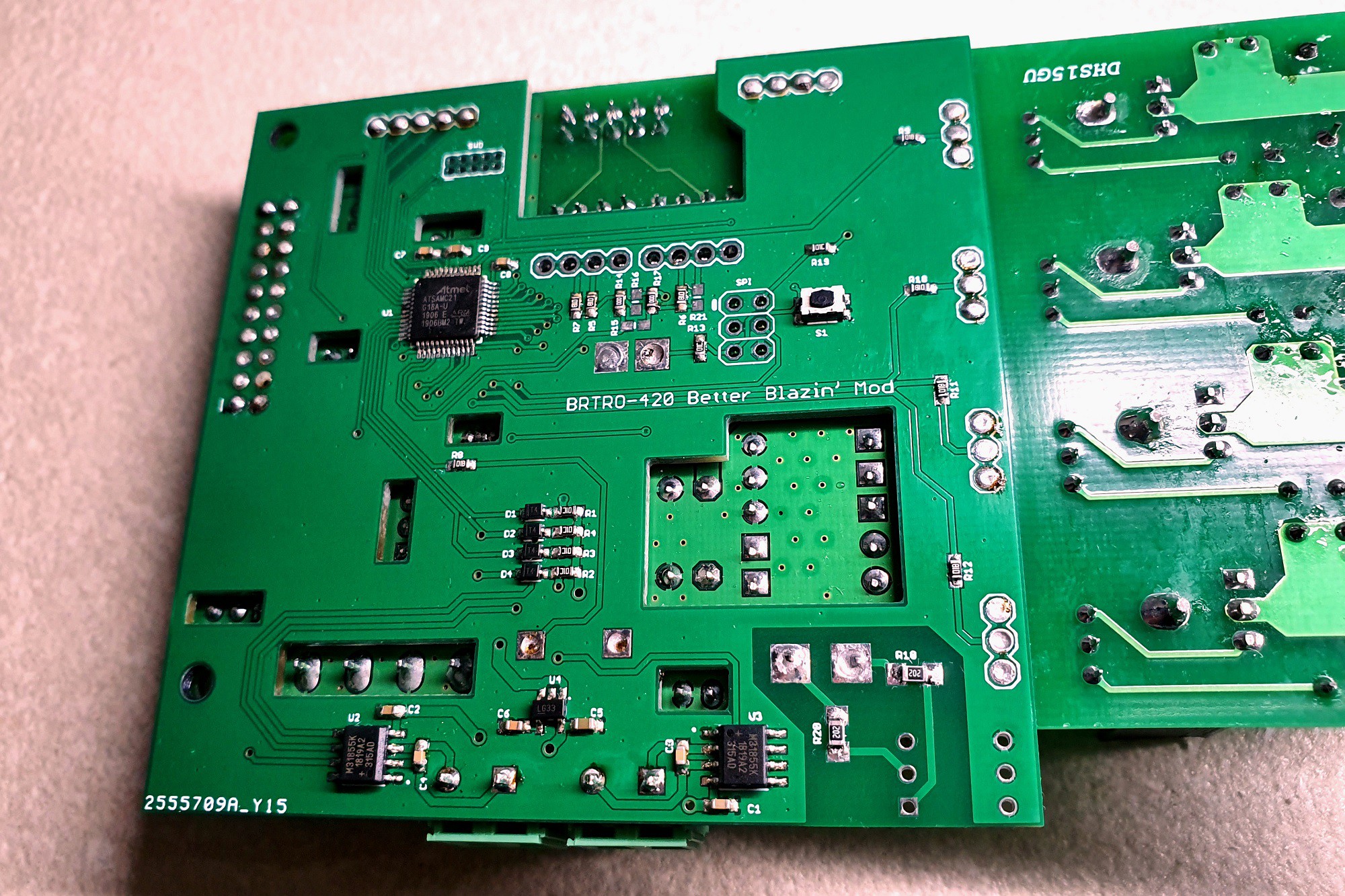
09/30/2019 at 11:52 • 0 commentsNow to solder the board on. You want to join the existing leads to the new holes. This is made easier with a fine solder tip and feeding in the solder:
![]()
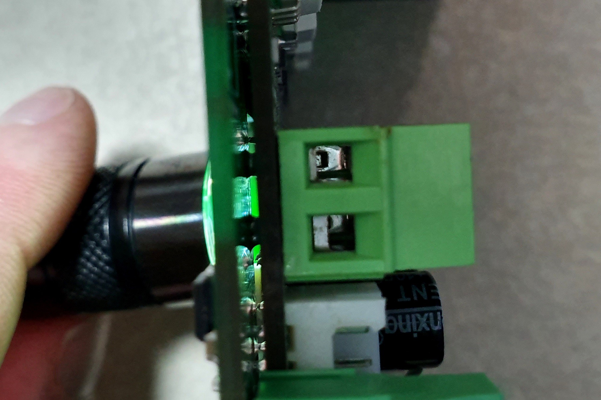
To check that pins have wetted, you can shine a light through the gaps in the PCB:
![]()
Et voilà:
![]()
Also, pop a jumper on the W1 pins near the existing MCU (or bridge them with solder); this is the DEBUG I/F pin. This places this MCU into serial bootloader mode (MD = 0, DEBUG I/F = 0) and effectively renders it inoperable.
New 5mm headers have been placed for the thermocouples. You could reuse the existing ones if you prefer.
-
Getting Ready to Blaze
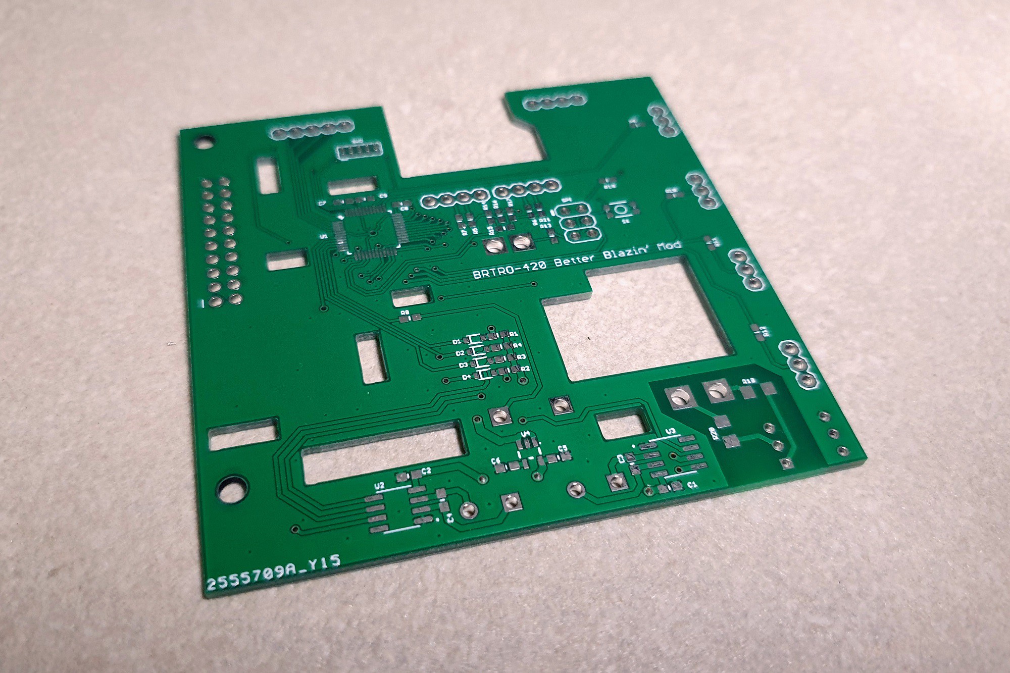
09/30/2019 at 11:17 • 0 commentsThe boards have arrived!
![]()
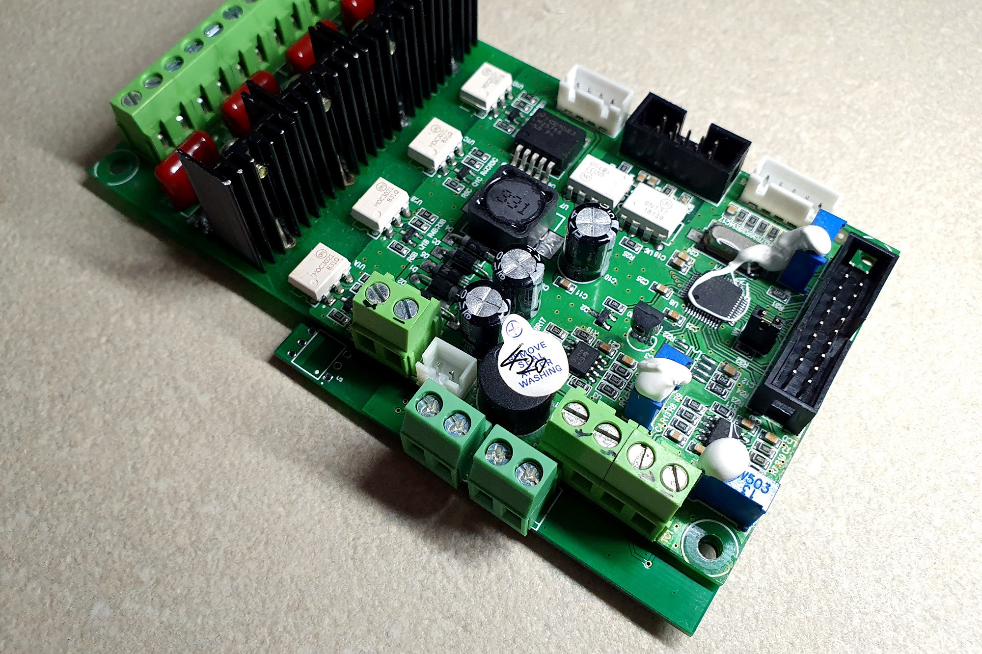
And are populated and fit just fine (after straightening some pins)!
![]()
If anyone is interested in this mod, let me know as there are a few spares.
BRTRO-420 Better Blazin' Mod
Modify the BRTRO-420 reflow oven to have an Arduino based reflow firmware, serial interface and cold junction compensation.
 Compare this to the existing display:
 Tools: