Close
0%
0%

8mm Film Scanner

Scan regular 8 and super 8 film and create a digital copy

Similar projects worth following
When a relative of mine passed, she left behind a lot of 8mm film reels. I figured too many to bring to a copy shop to digitise them. I searched the internet and found several solutions - from ready to use copy machines to dyi projects. However, non of them fulfilled my requirements, but my curiosity was sparked and I thought of making one by myself.
I went already through some iterations of designs to create a reliable, easy to use 8mm film copy machine.
I learned a lot along the process: about the raspberry camera, fusion 360 as a tool to design the parts, easyeda to design a pcb and OpenCV to analyze the pictures taken. All this things where a first for me - and I'm still learning :)

The basic idea is to move the 8mm film frame by frame with a stepper motor and take a picture of it. Afterwards putting the images together to a film.

The frames are quite small (abt 5x4mm) and in order to have a smooth playback of the film, the positioning and cropping of the images is critical. 

After initial tests, I decided to use OpenCV for positioning and cropping. 

First comparisons between a "professional copy" and the built here looks promising, but I believe that especially the camera settings still can be improved a lot.

Here a short video made with the scanner: (original from 1976)


The 3D print:

Originally I printed everything in PLA. But after several hours of scanning I realised that the temperature of the stepper gets too high and some parts started deforming.

I printed the parts near the motor with ABS and that works just fine. (the stl files are sorted by material used)

OpenCV:

Even that the 0.9 degree stepper usually positions the frames very precise, there are variations especially when glued parts of the film, which are thicker, pass by. 

To ensure that the frames are always positioned in the middle of the cameras focus, I search for the contour on the left side - the sprocket hole in the film.

If that goes out of a certain tolerance, the stepper will readjust the frame.
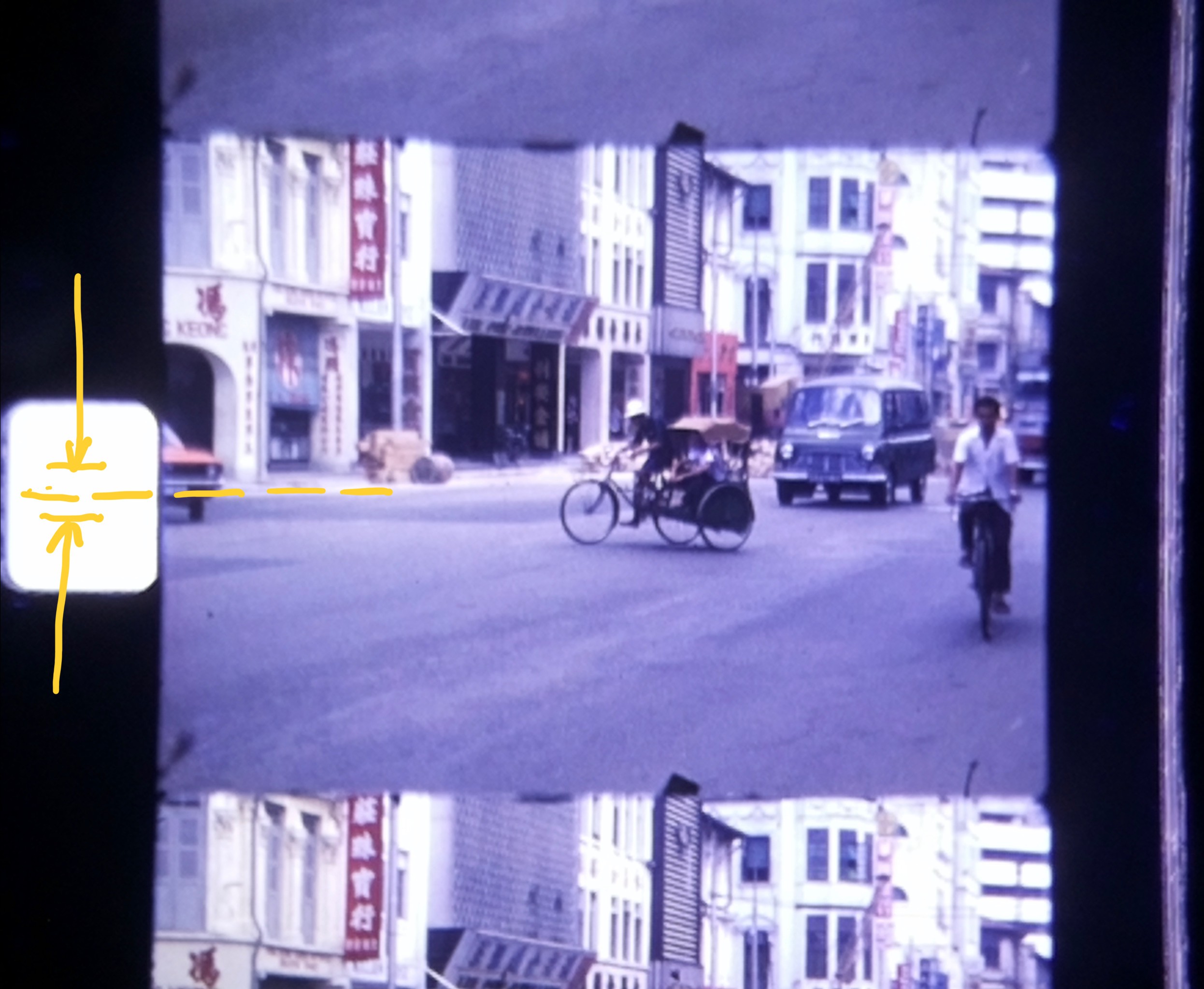
scanned image

After scanning all the frames, the software goes in another mode - calibration and crop.

A rectangular frame (the green one) is moved to the desired part of the frame. This is necessary because the frame position relative to the sprocket hole is camera specific. 

After checking the right position of the rectangle with some random frames, the cropping is started with the push of a button. The frames are now cut out precisely and once done, they are put together with ffmpeg to a film.
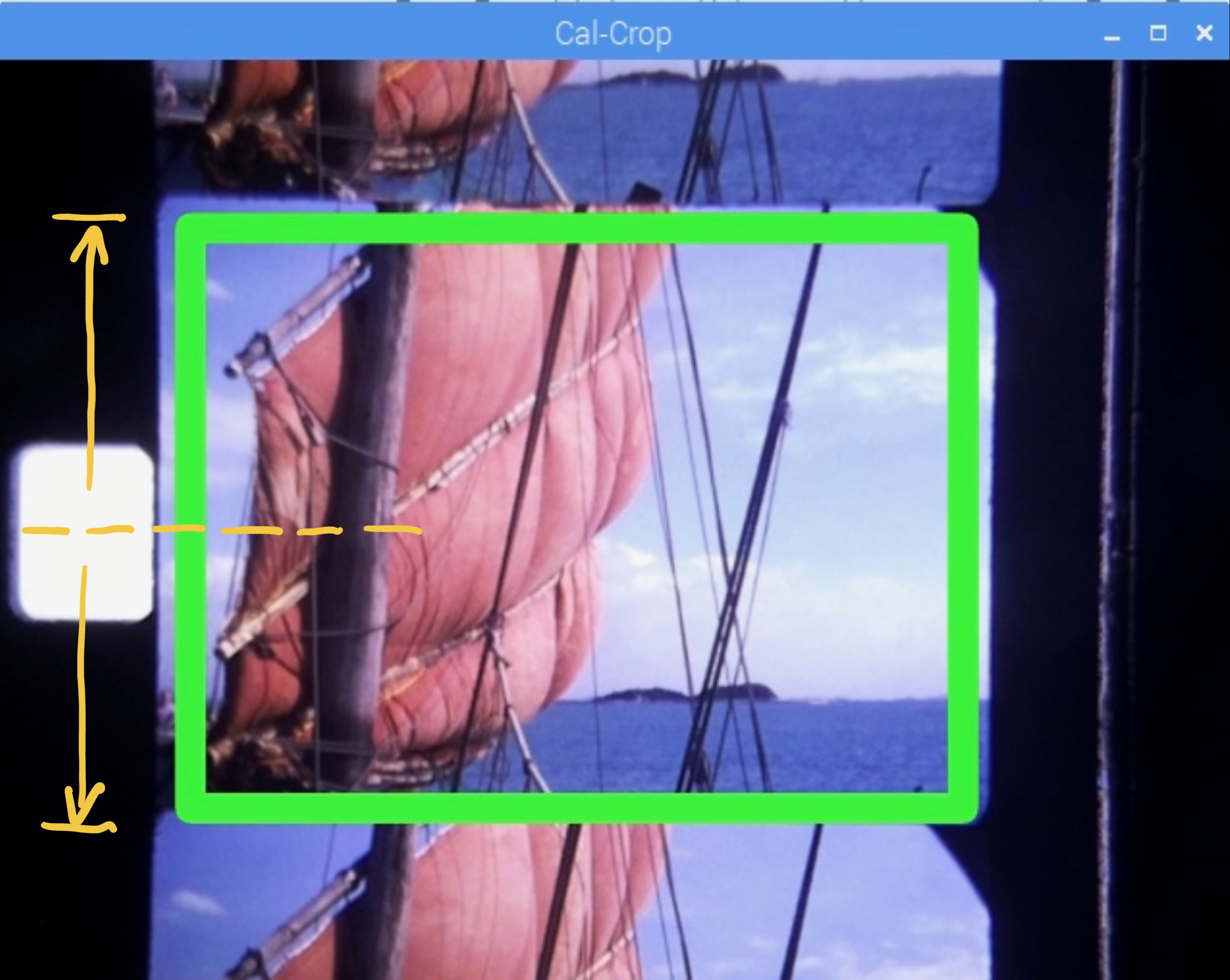
image with calibration rectangle

film copier gen 7 v10.step

3D files for editing

step - 3.39 MB - 08/17/2021 at 09:23

Download

Gerber_film_copier.zip

Zip Archive - 32.44 kB - 10/29/2020 at 05:36

Download

PCB.zip

PCB picture (pdf) files

Zip Archive - 60.01 kB - 05/13/2020 at 06:22

Download

Schematic film copier.png

Portable Network Graphics (PNG) - 532.58 kB - 09/07/2019 at 16:06

Preview

  • 1 × Raspbery pi Model B
  • 1 × Raspberry Pi Camera V2
  • 1 × 3.5 inch 26P SPI TFT LCD Display Screen with Touch Panel 320*480
  • 1 × Mini N20 Micro Speed Gear Motor 6V 60 U/min
  • 1 × Photo Interrupter Sensor Module

View all 25 components

View all 10 project logs

  • 1
    Assembling the core

    Beside the printed parts on the picture, you'll need:

    Screws: 2pc M3x20mm, 1pc M3x12mm. 1pc M2x8mm

    Nuts: 5pc M3 Self locking, 1pc M2

    Magnets: 9pc 6x3mm

    Bearings: 6pc 3x8x4mm

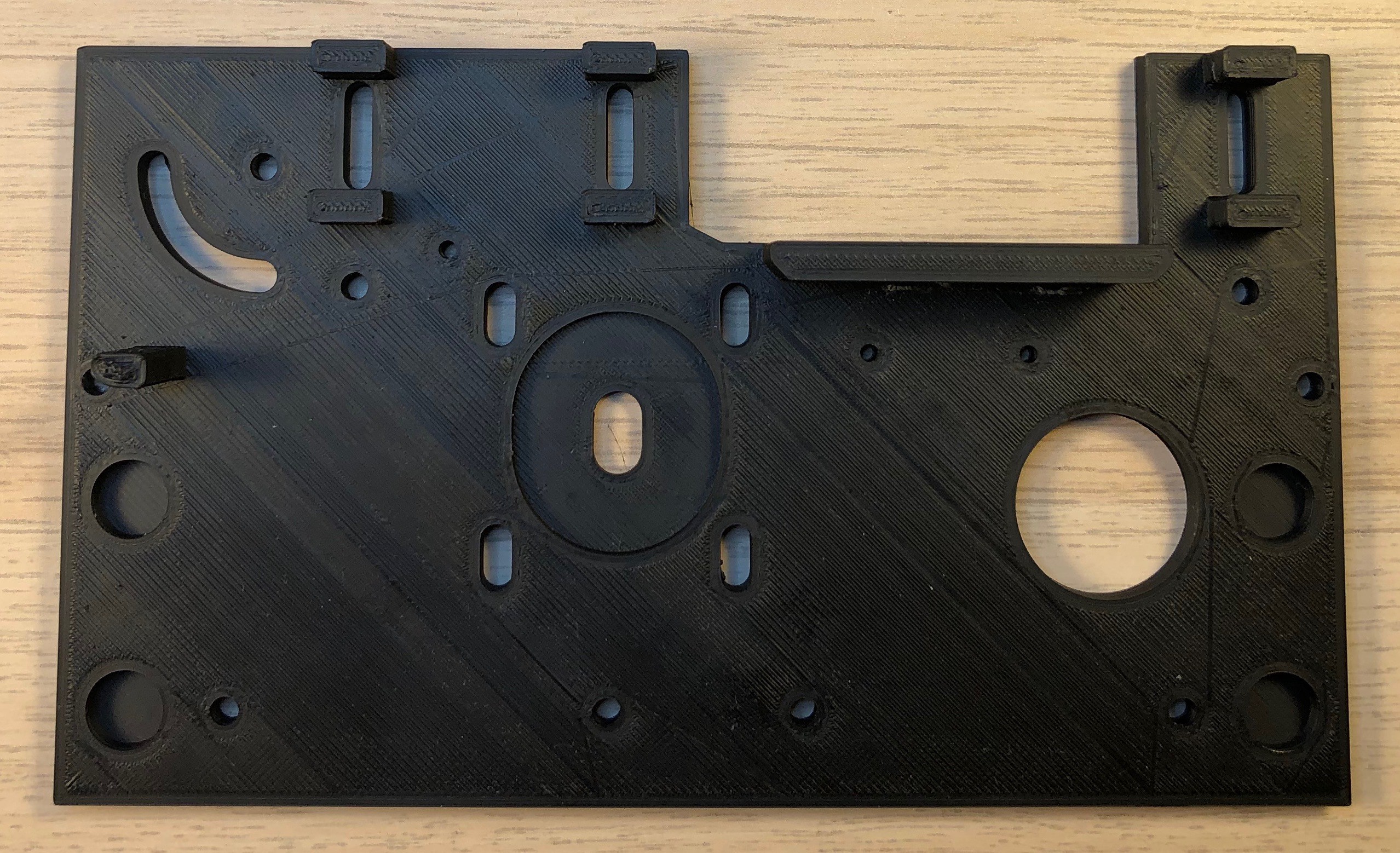
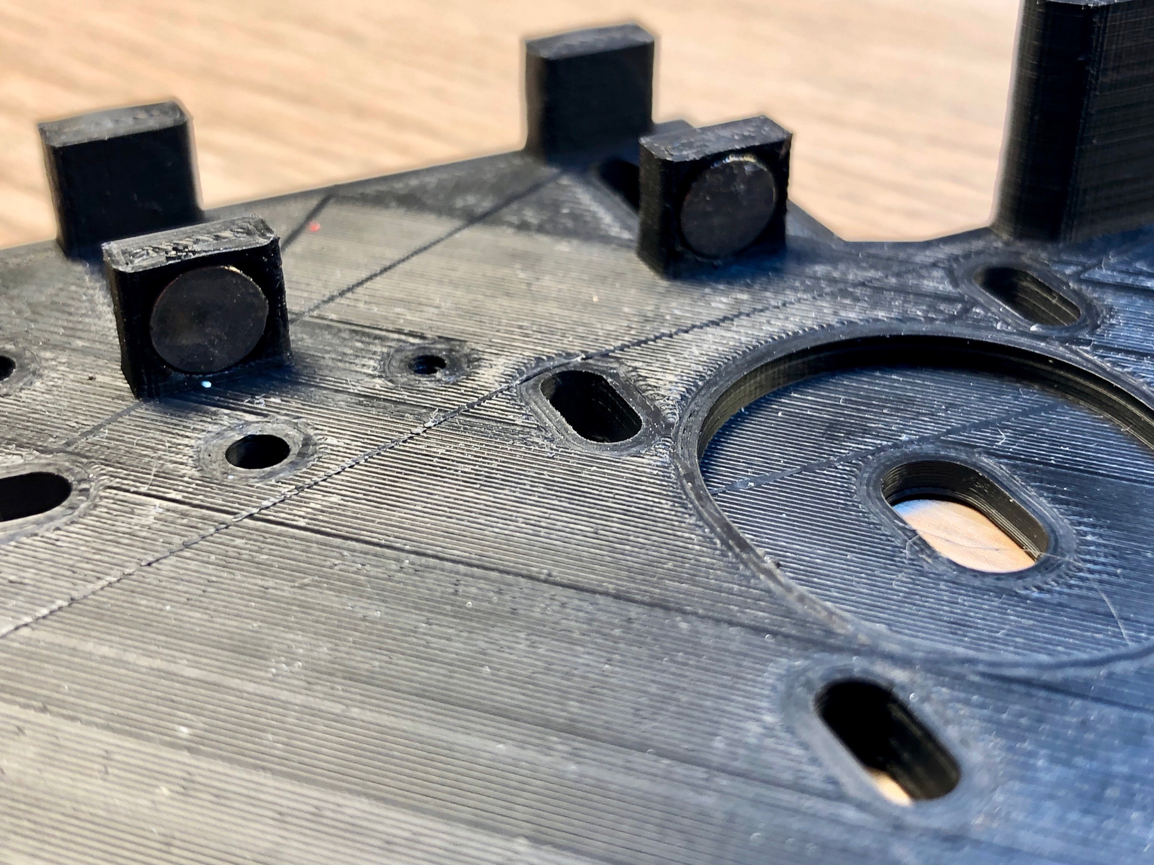
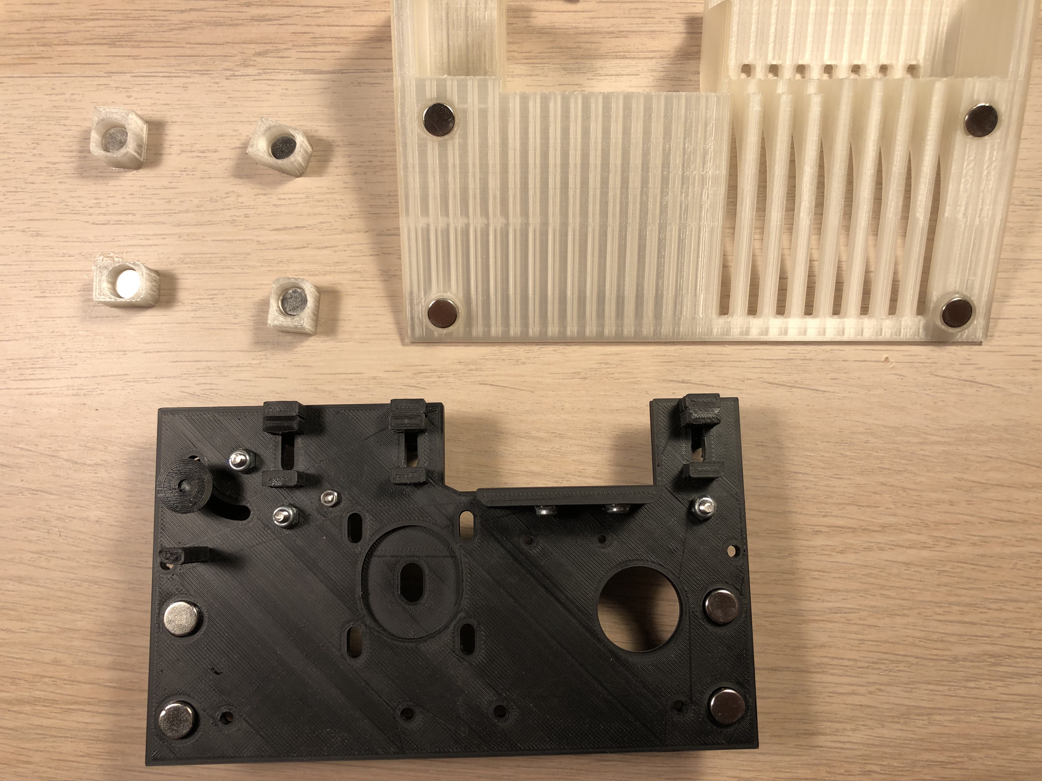
    Glue the magnets into the holes of the mount plate as well as the 3 roll axles:

    Important! - Check the polarity: the axle hast to stick to the magnets in the mount plate in the upper and lower position.

    Magnets in Mount plate

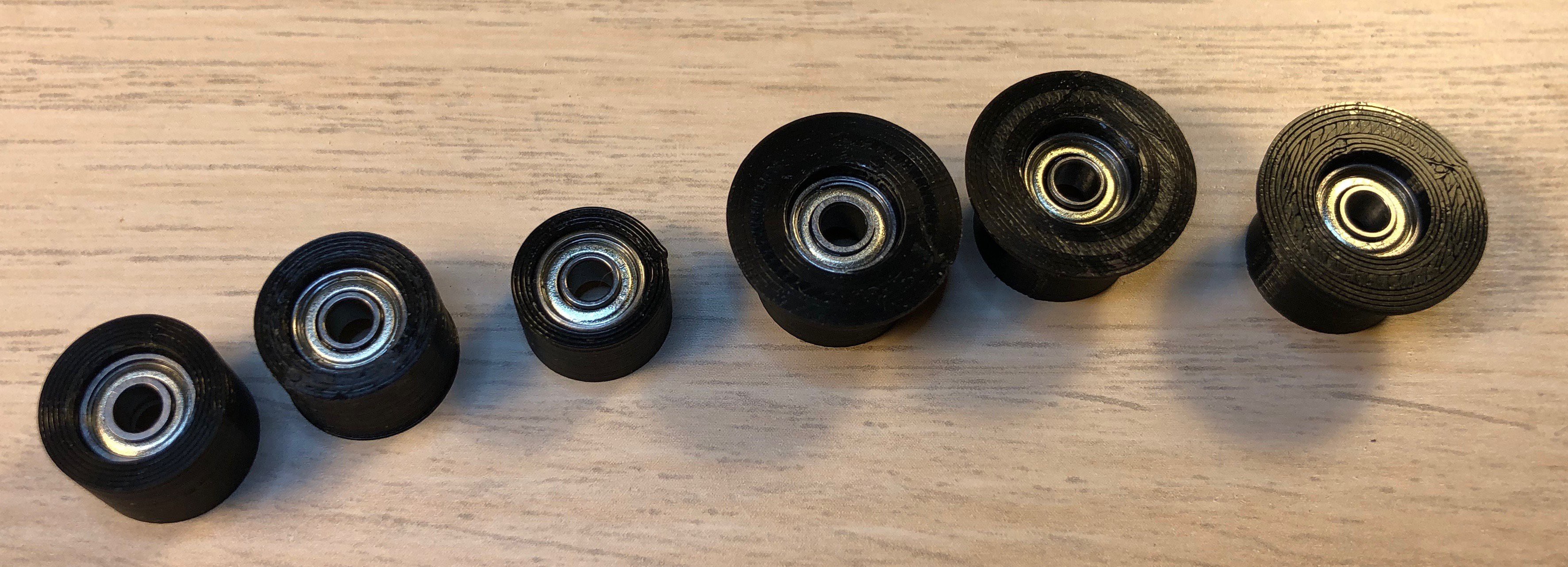
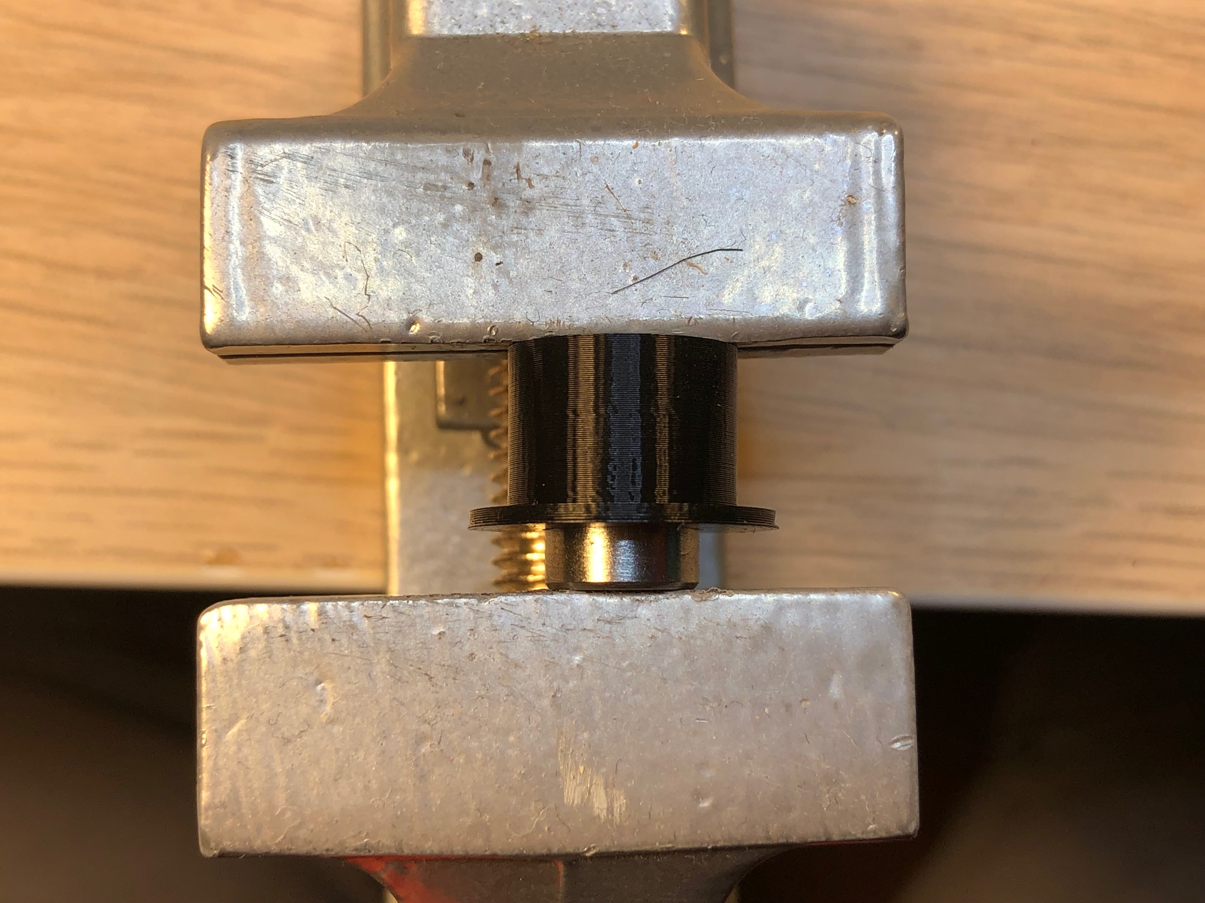
    Push the bearings into the rolls: Don't worry to use some force - I use a vise for that.

    Afterwards glue the sides on the 3 larger rolls.

    all bearings in place
    assembled rolls
    using the vise

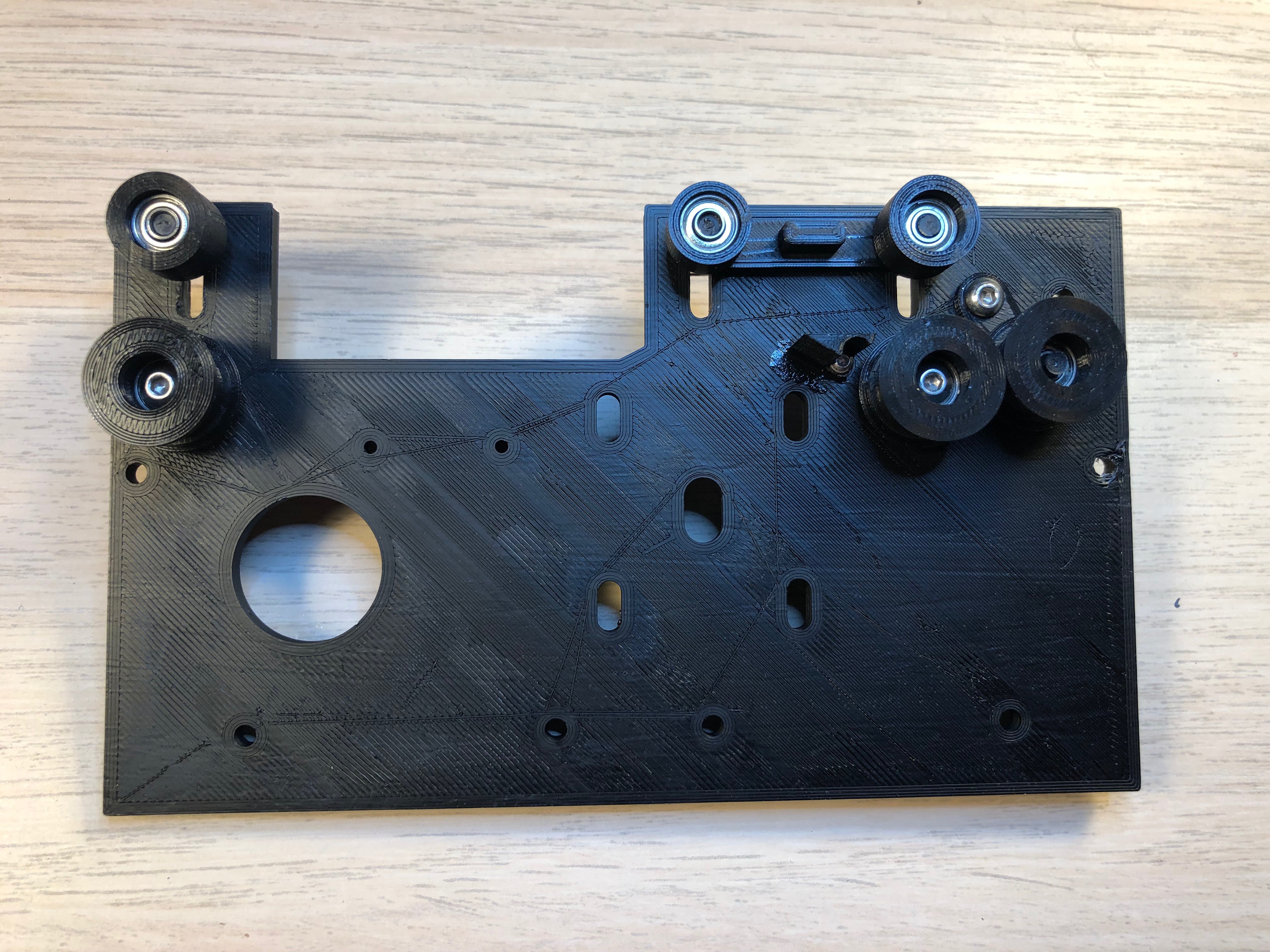
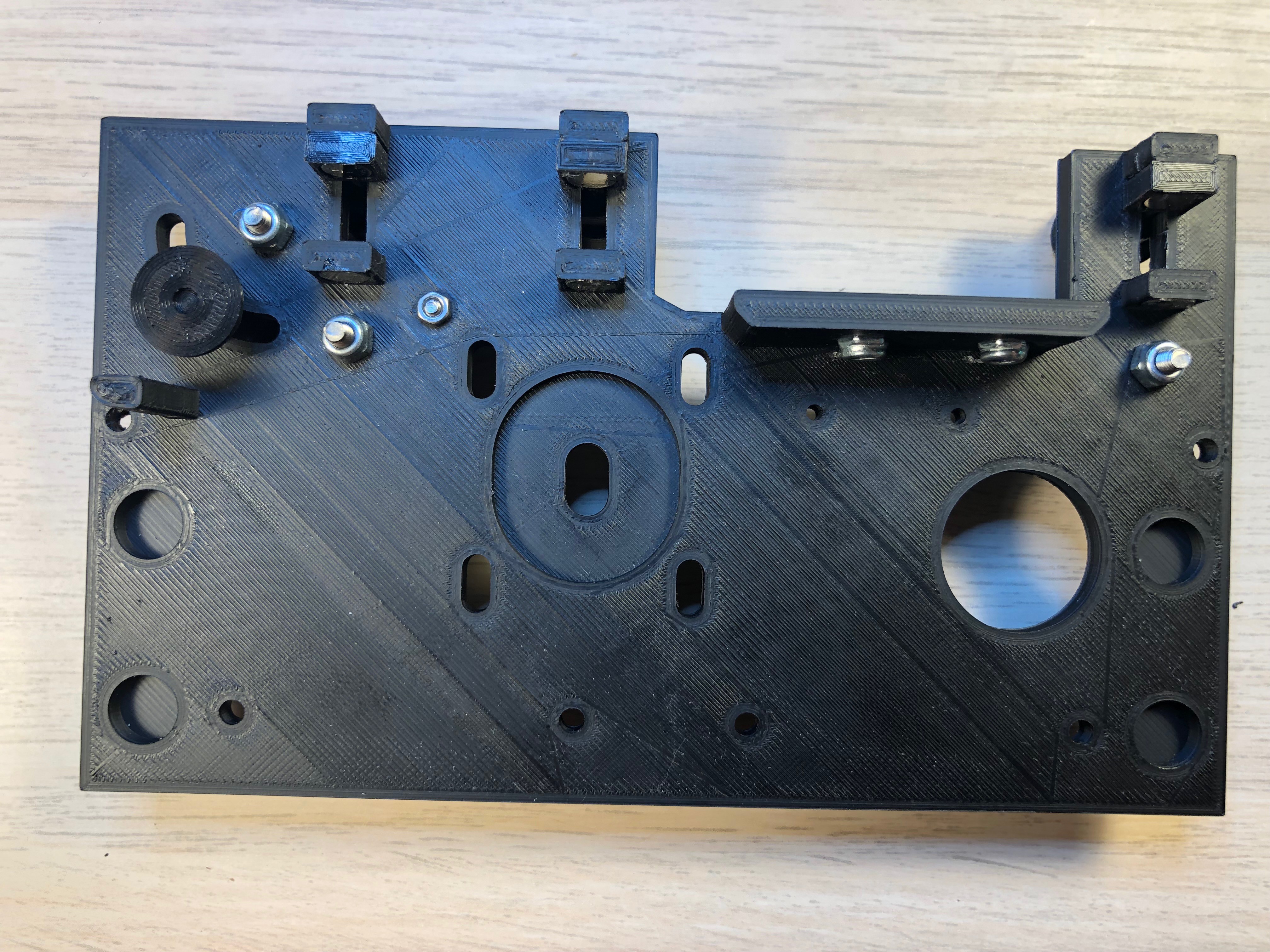
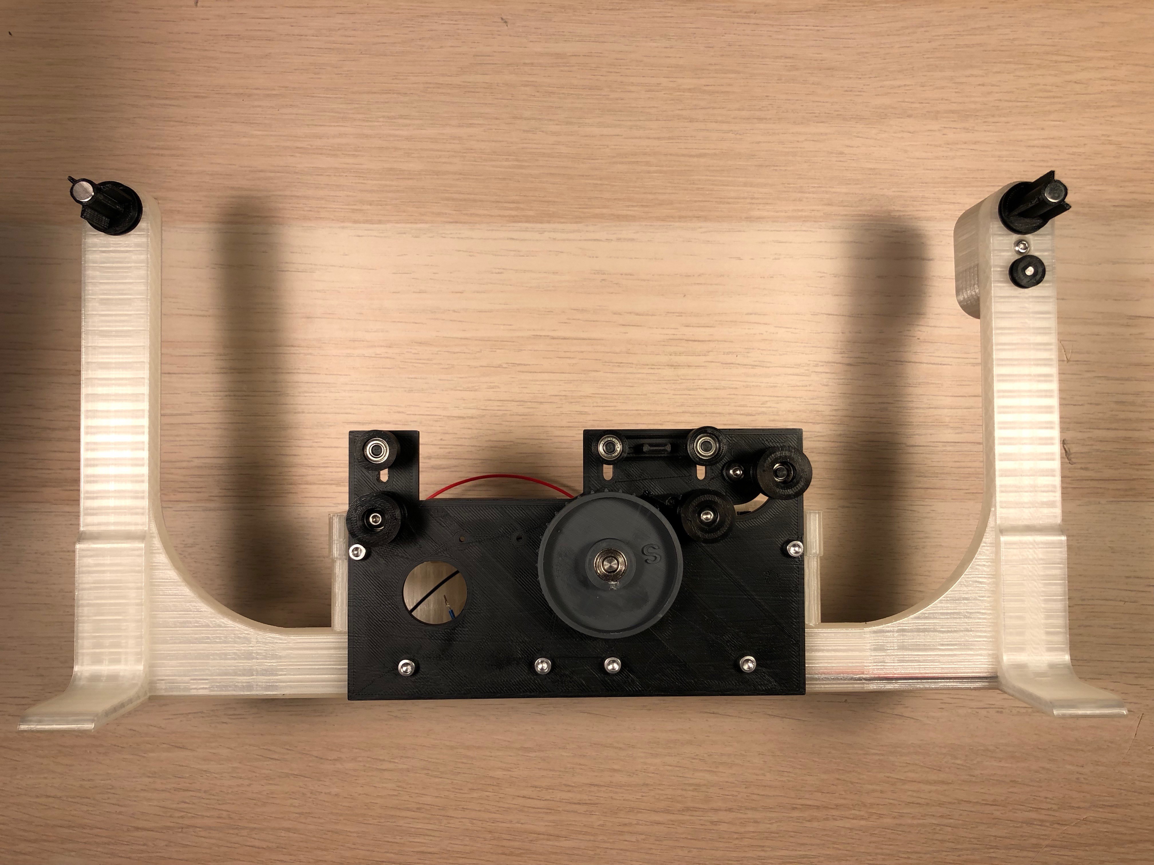
    Now put the axles through the mount plate and the roll mover (or roll spacer) and push the rolls on it. No need to adjust them yet. 

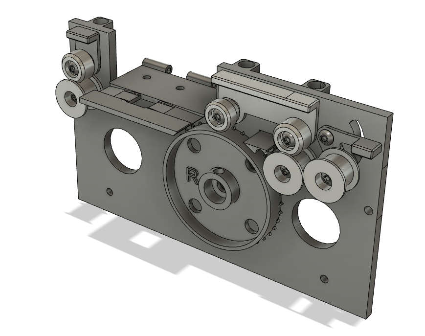
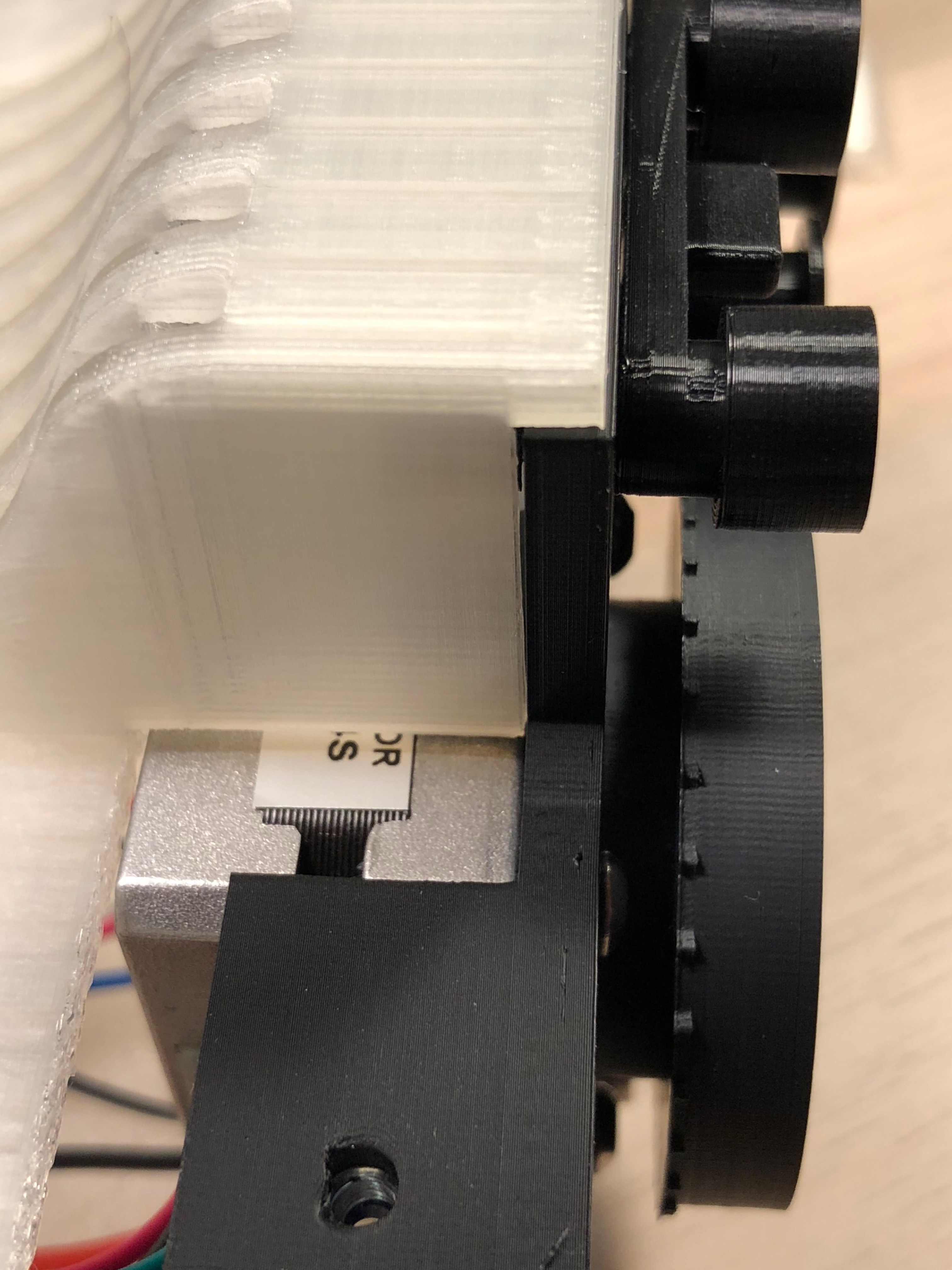
    Mount the 2 lower rolls with M3x20 screws and the interrupter lever with an M3x12mm screw. The film clearer is mounted with the M2 screw. Add 2 M3 nuts at the bottom of the latch (see picture of the back view)

    Ensure all rolls are running smooth and the upper rolls are locking in the upper and lower positions. 

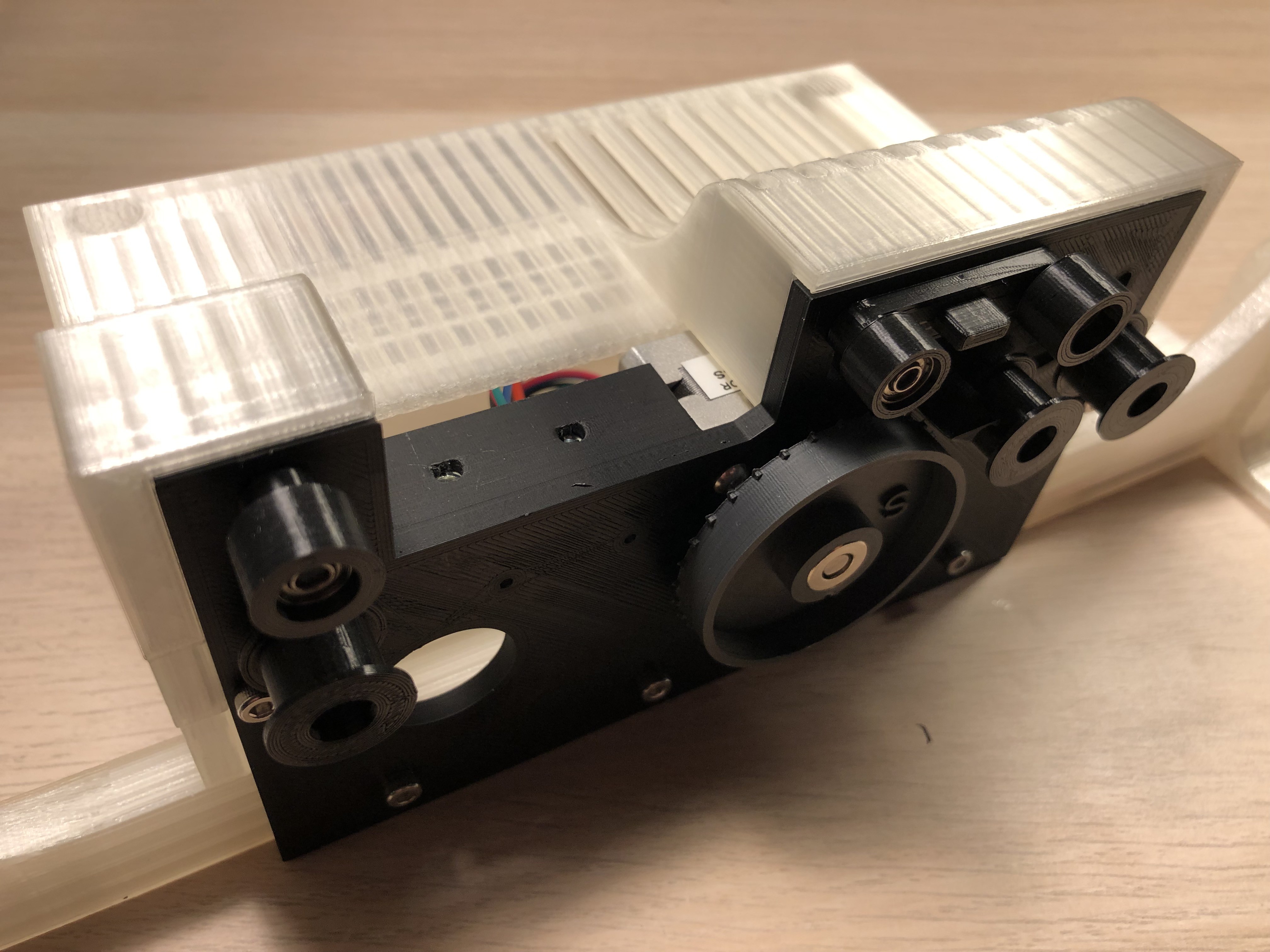
    The result should look something like this:

    Front
    Back

    move on the step 2

  • 2
    Assemble the motorized spool holder

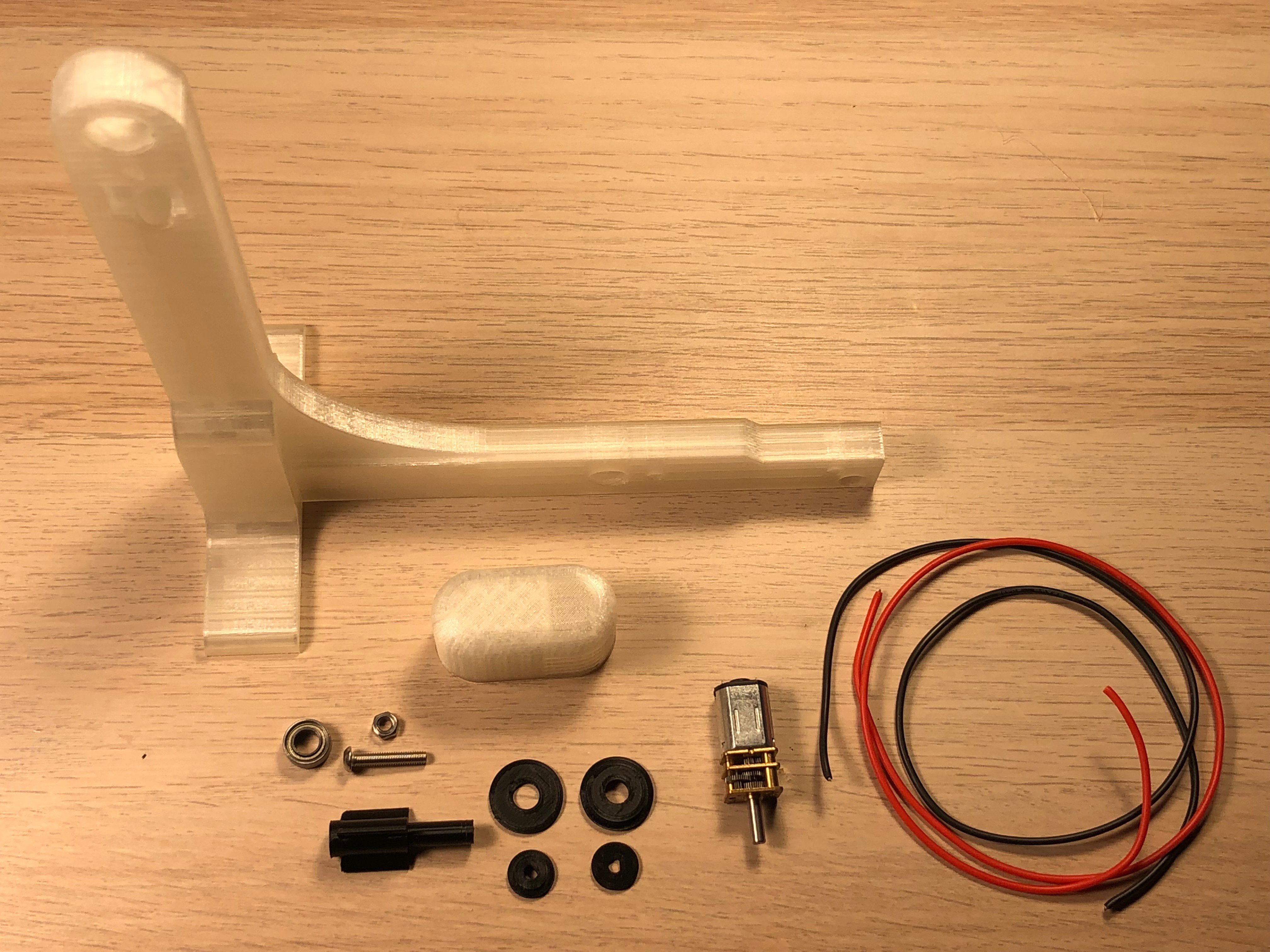
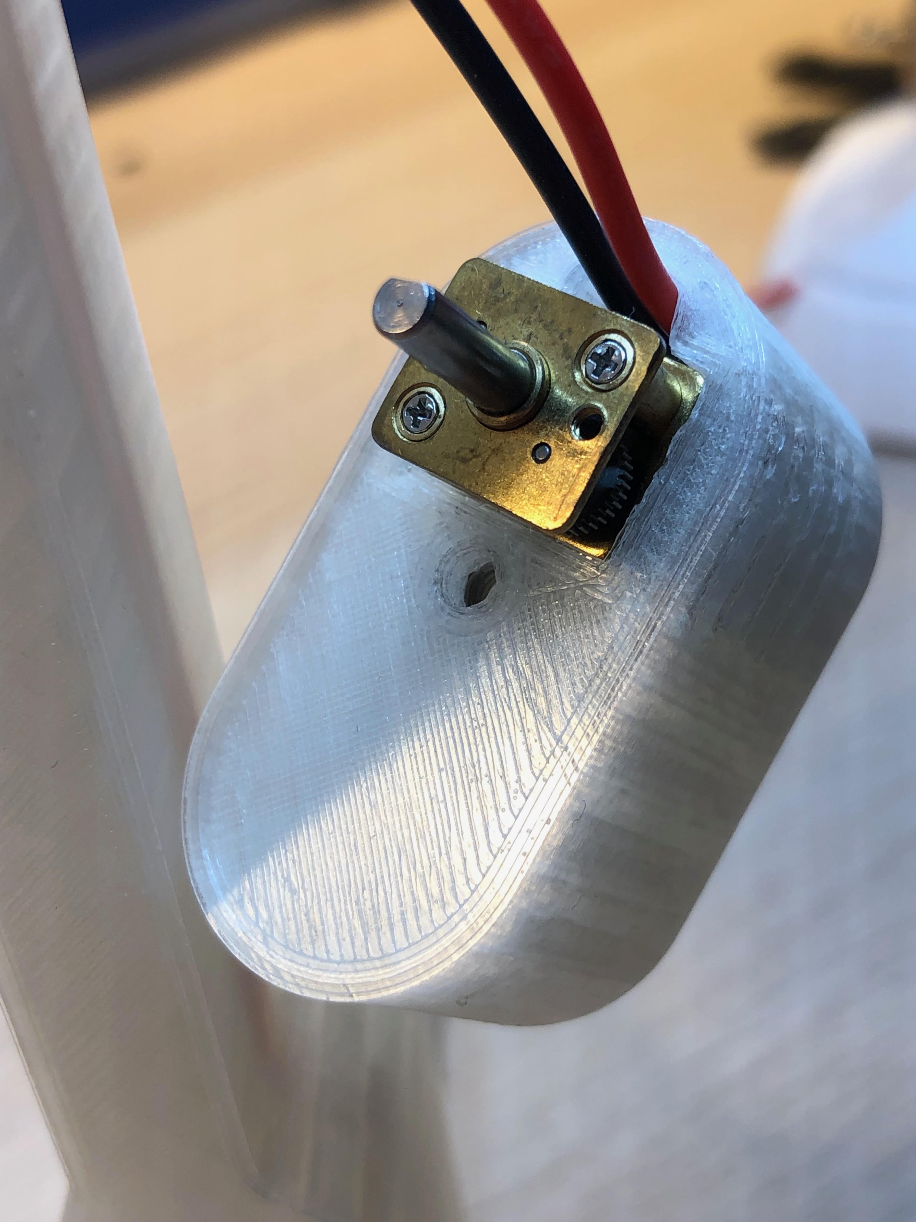
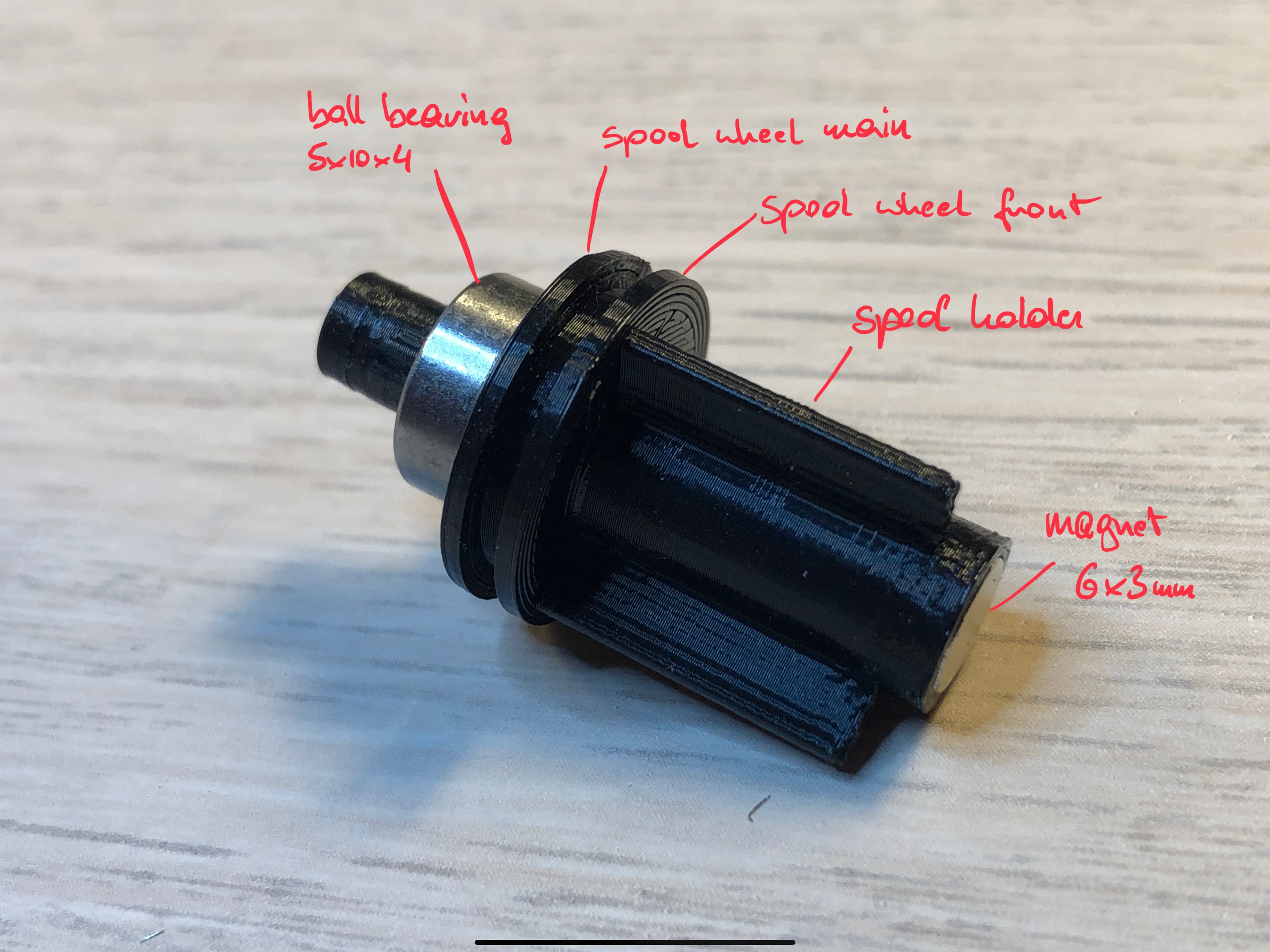
    Beside the printed parts as shown, you'll need the geared motor (6V 60U/min) a ball bearing 5x10x4mm a M3x16 screw + nut a magnet 6x3 (not on the photo) and some cable.

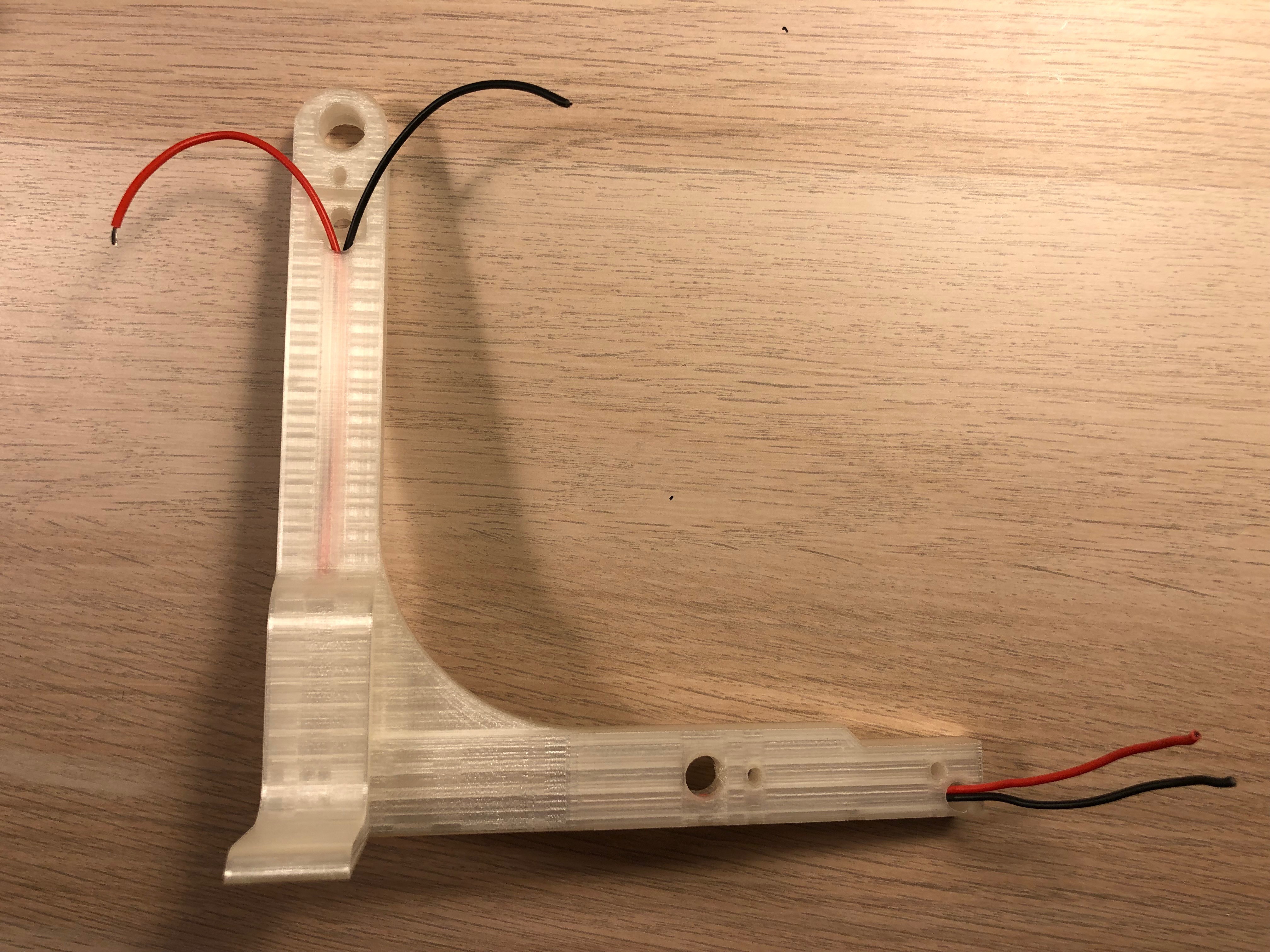
    Pull through the cables:

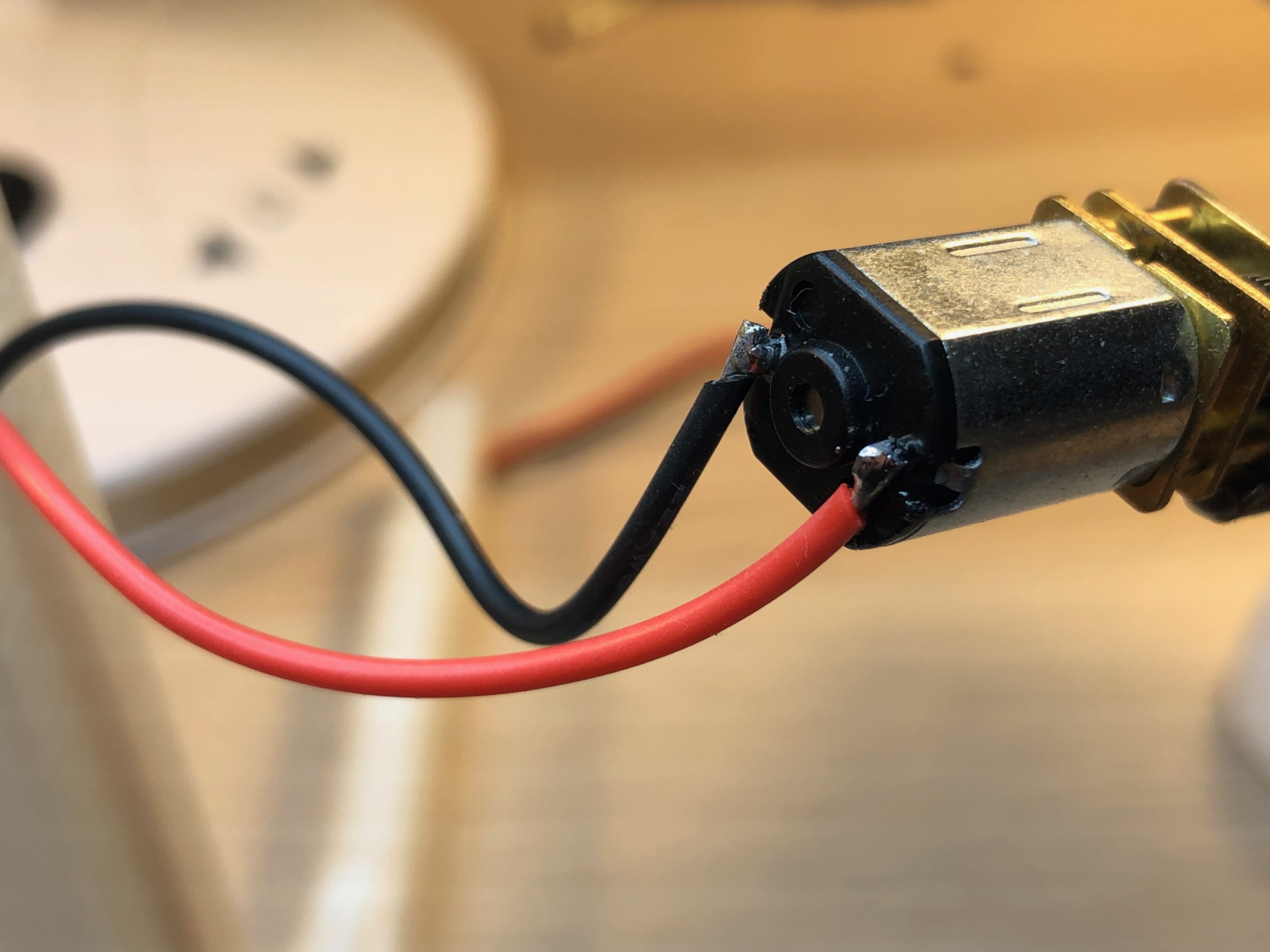
    Solder the geared motor:

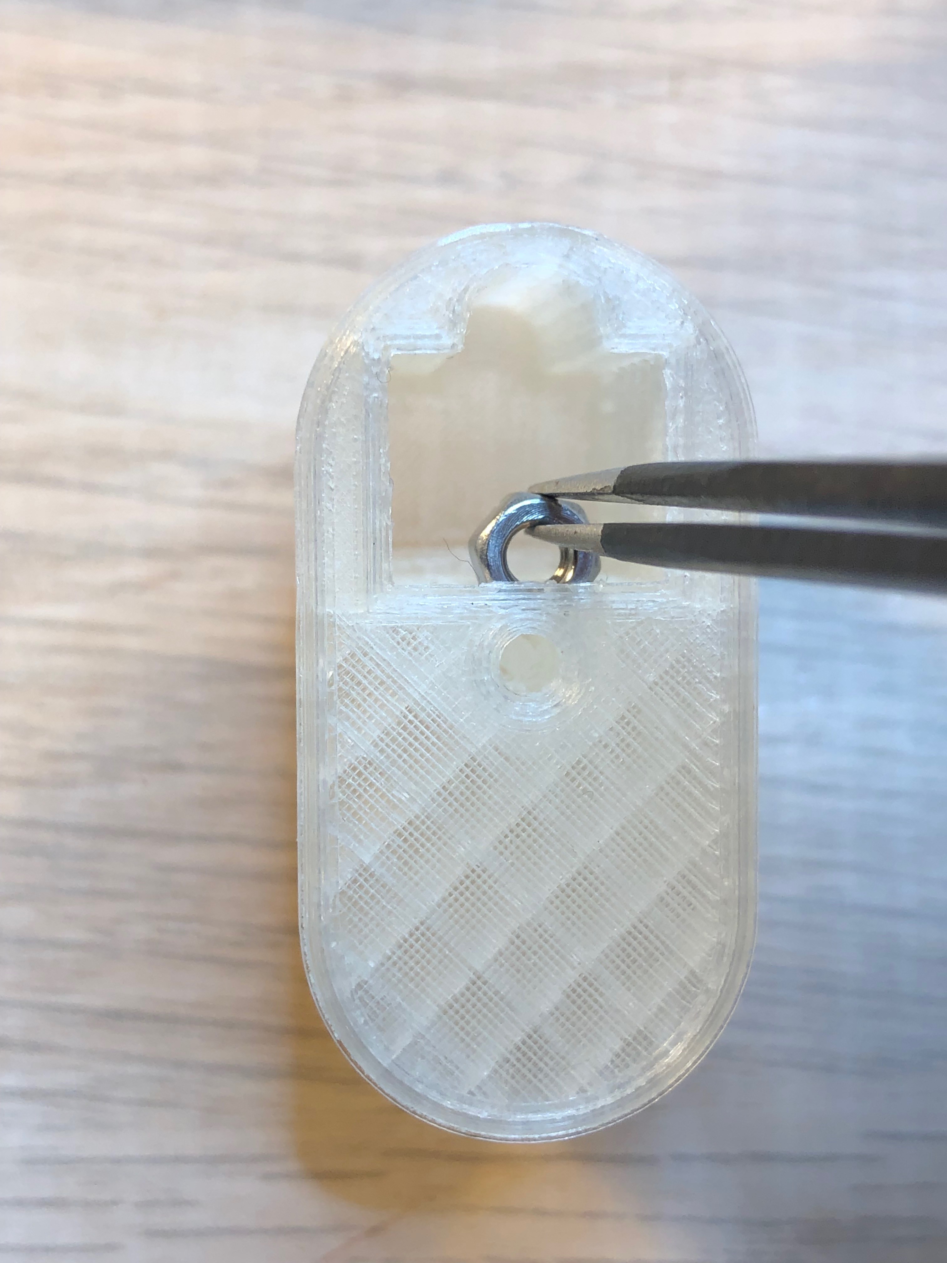
    Put the nut in the motor cover:

    Put in the motor:

    Use the M3 screw to mount it to the arm:

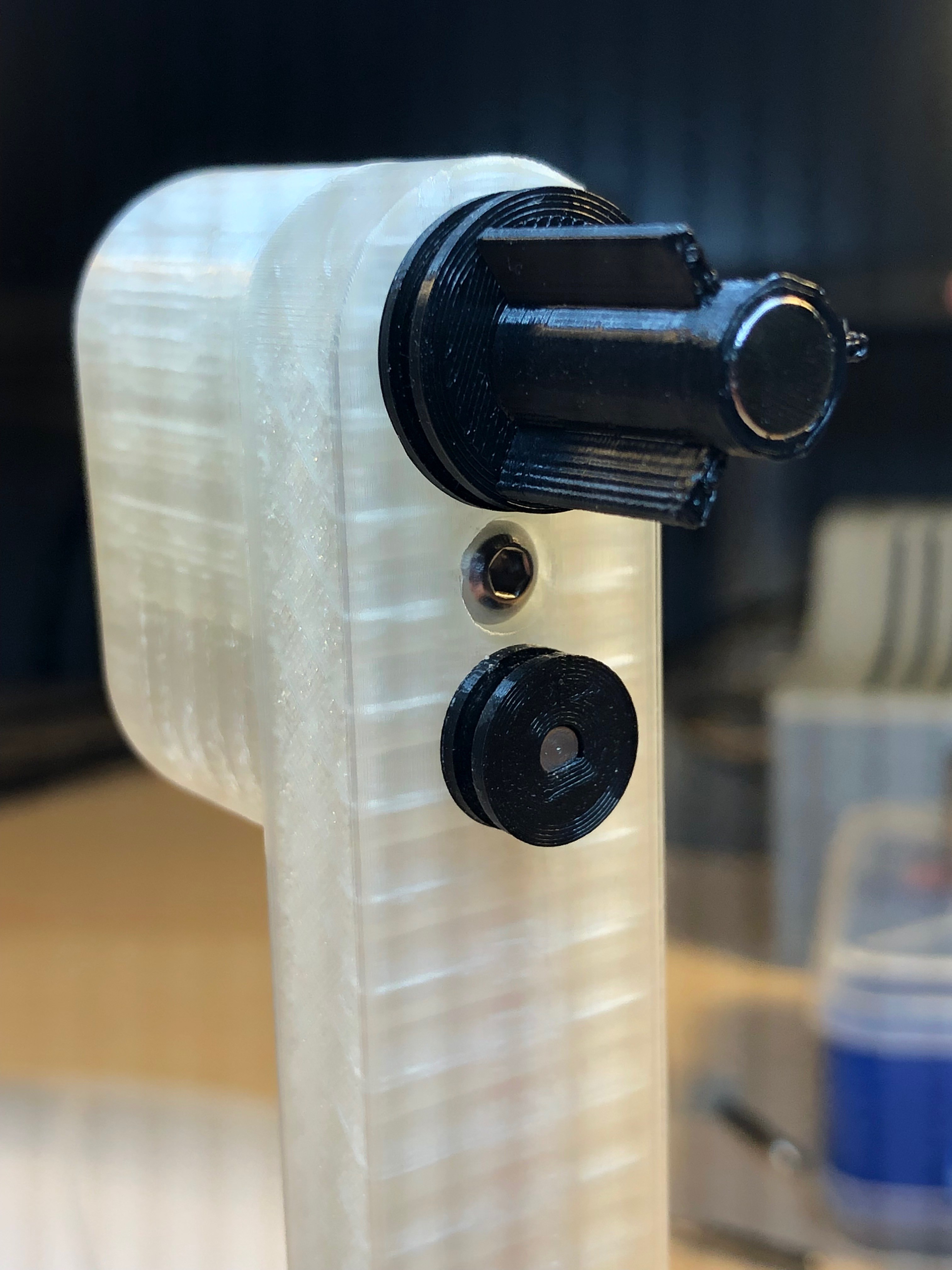
    Assemble the spool holder by gluing the printed parts together and push the bearing on - it should sit very tight! Glue in the magnet. Important: You will find 2 very similar parts in your prints for the spool holder, one for each side. Here you use the slightly longer one.

    Push the holder into the arm - also here the bearing should fit very tight.

    Put the spool motor wheel main part onto the motor axle and glue the motor wheel front to the main. (not the axle)

    Assemble the 2nd spool holder and put it into the other spool arm.

  • 3
    Putting together what we've built so far

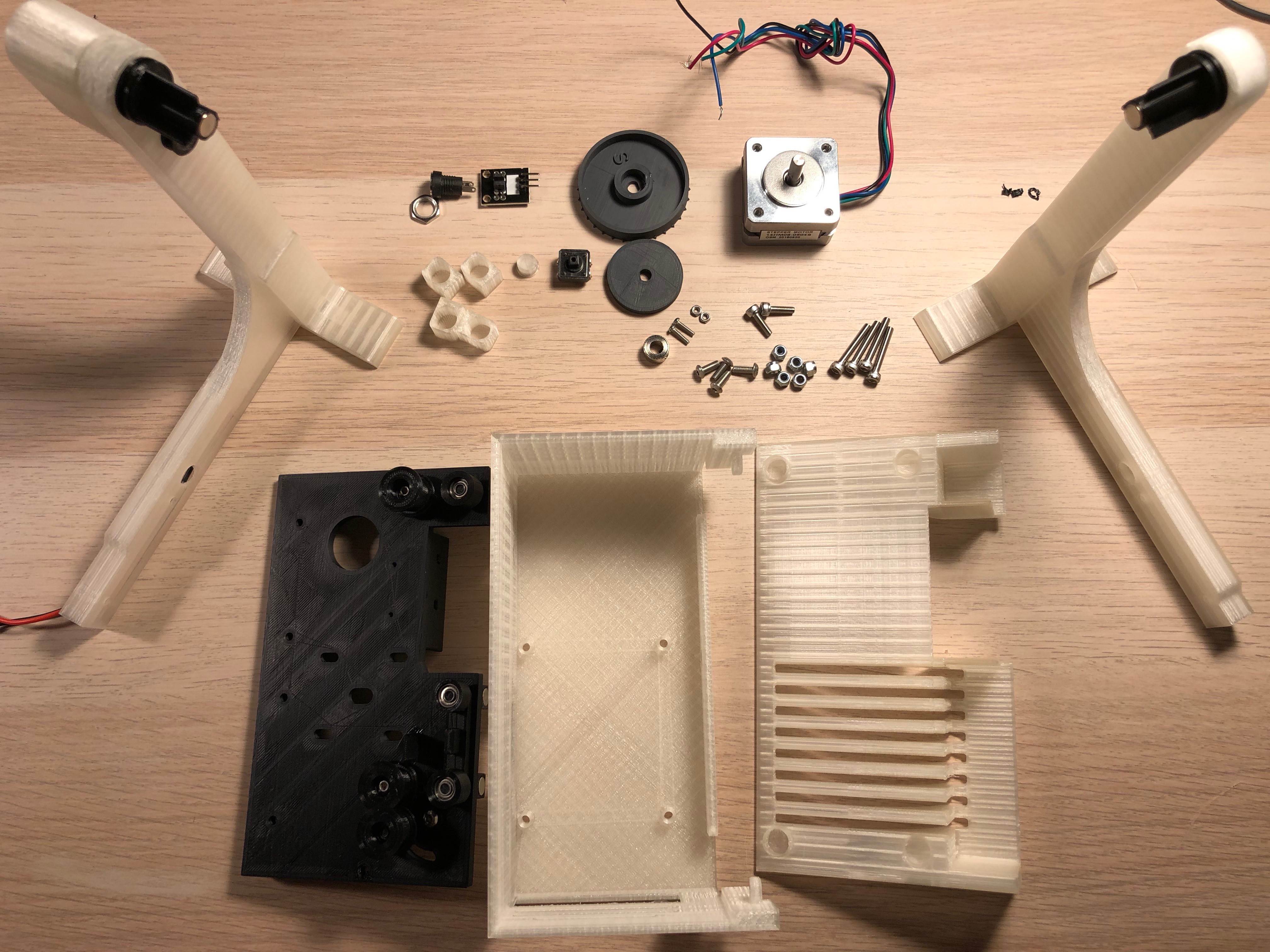
    You'll need screws: 4 M3x20, 2 M3x10, 4 M3x6mm, 6 self locking nuts M3, 2 M2x6 + nuts, 12 magnets 8x5mm, Photo Interrupter Sensor Module, the stepper motor, 1 Steel Shaft Sleeve 5.05mm, 1 DC Power Jack 5.5 x 2.1mm, 1 Button 12x12mm

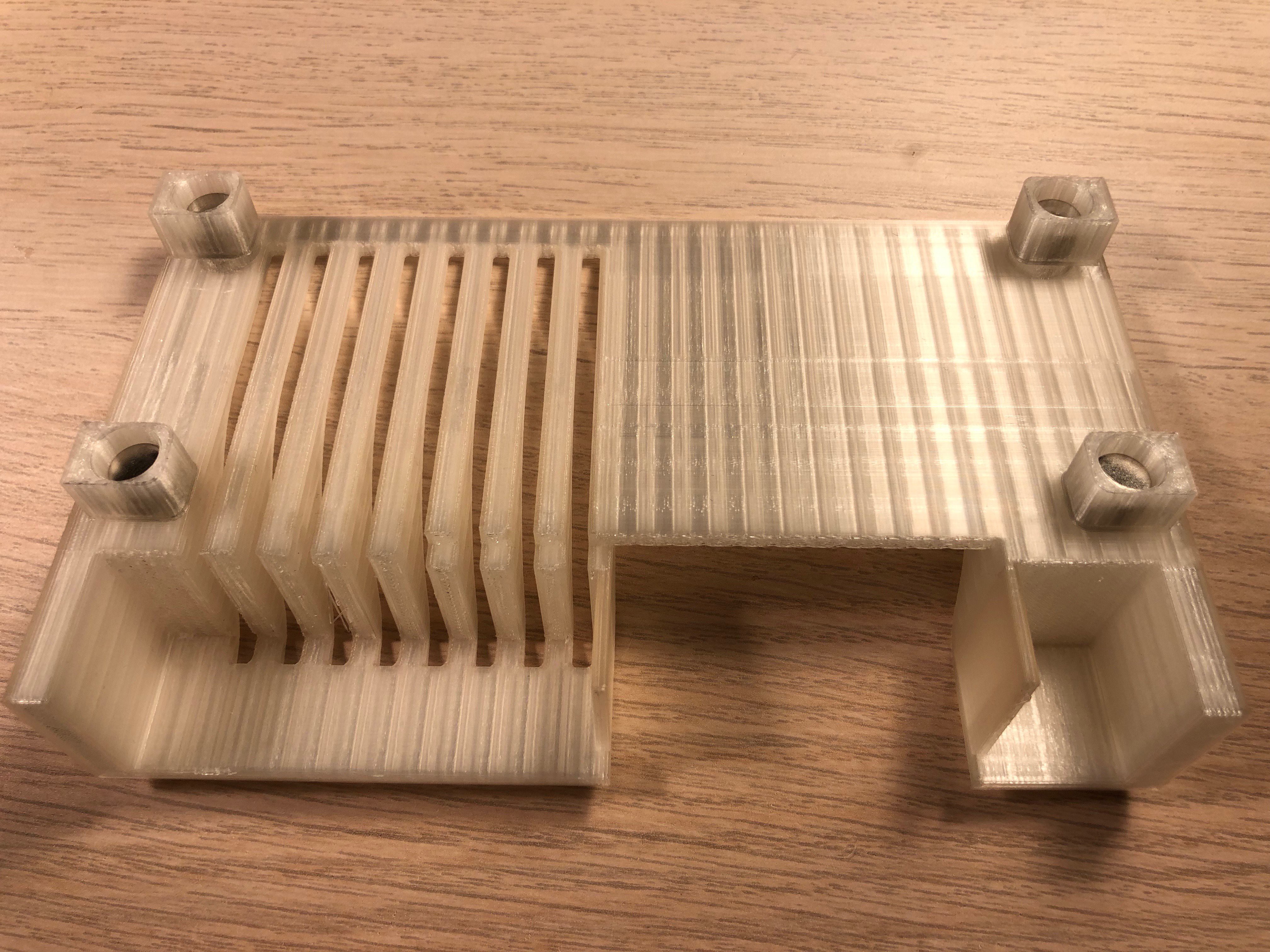
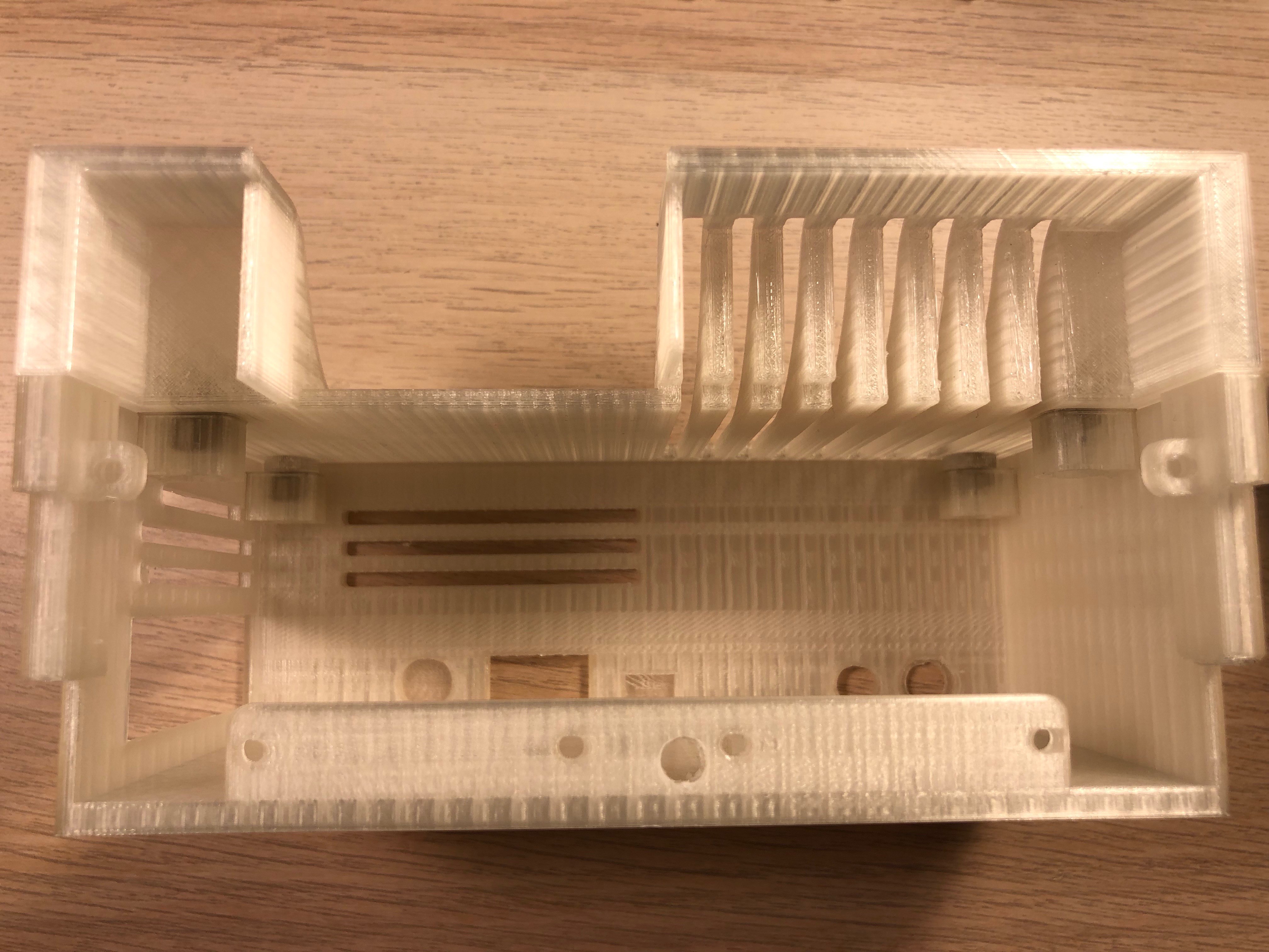
    Glue the magnets into the holes:

    Polarity: the Magnets in the 4 magnet holder should stick to the magnets in the cover like that:

    Add a bit of super glue on the outer ends of the holders and put the cover on the back cover box, that way the cover will fit exactly on the box.

    Mount the power jack and the button. I use hot glue for the button. 

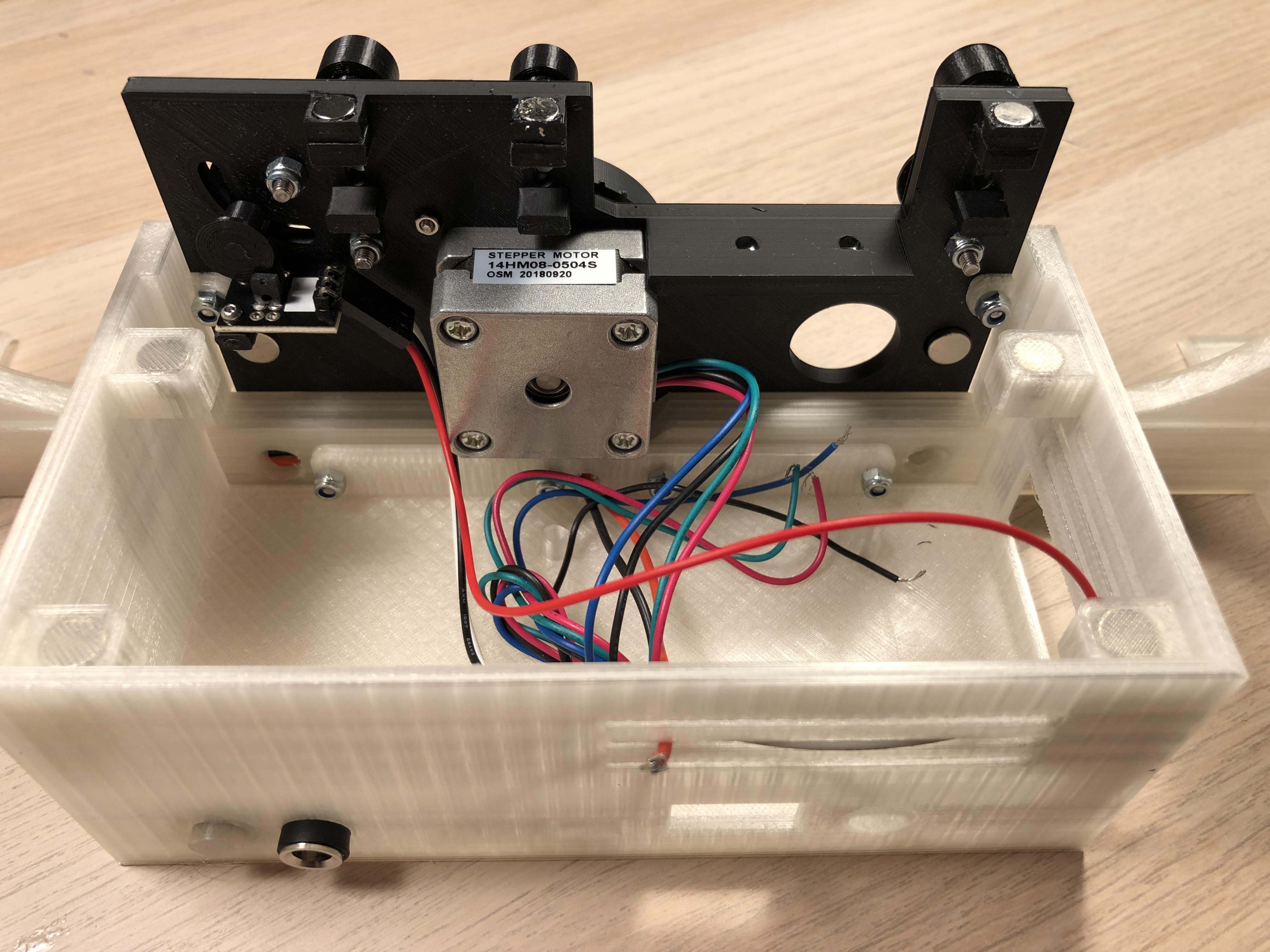
    Add the photo interruptor with the 2 M2 screws, the stepper with the 4 M3x6mm screws and mount the plate to the box. The M3x20 screws have to go through the mount plate, the spool arms and the box. 

    Push the sprocket back spacer on the stepper axle, a a few drops of glue onto it (the spacer - not the axle!) and push the sprocket with the shaft sleeve onto the axle.

    The cover should fit nicely and the magnets will hold it in place:

View all 8 instructions

Enjoy this project?

Share

Discussions

doublehead wrote 01/01/2021 at 22:40 point

Great project!

Could I ask you about photo sensor? Which one is used? And how precise your machine can position film frame under the camera?

I've trying to build scanner with a same idea. But have some problems with precision of positioning of film frames under the camera using perforation. I've tried laser detector (both direct and reflection modes), UV LED and UV detector, mechanical sensor - but it couldn't give me required accuracy...

  Are you sure? yes | no

Anton wrote 01/15/2021 at 01:46 point
Hi!

the precision of the stepper is not 100%. Thats why I use OpenCV to adjust the frame as well at to crop it out.

  Are you sure? yes | no

FORART fe wrote 10/01/2020 at 06:58 point

Hi there, cool project mate !

It would be also great to establish some kind of collaboration with other DIY-digitizers projects:

https://hackaday.io/list/175104-diy-film-scanners

Hope that helps/inspires.

  Are you sure? yes | no

Federico wrote 05/22/2020 at 14:10 point

Very interesting project, I've got a lot of old 8mm films shot back in the 60's and 70's and I'd really like to digitize them.

Since I dont't have a 3D printer at home, I would like to ask you if someone among you has tried online 3D printing services and the average cost to have all the parts printed.

Thanks for your help!

Federico

  Are you sure? yes | no

Anton wrote 05/28/2020 at 08:24 point

Federico, I personally have no experience with 3D printing services. 

Generally most of the parts are easy to print and not critical in regards how precise they need to be. Only exception are the ones that I indicated to print with a 0.25mm nozzle (sprocket and the film guides.) The ones I printed in ABS need to be printed in something temperature resistant. (not necessarily ABS, but PLA got too soft during operations and started deforming)

Maybe that helps in the selection of a service provider. 

  Are you sure? yes | no

Federico wrote 06/02/2020 at 17:37 point

Thanks Anton. I'm considering buying a 3d printer, not only it's cheaper than having all the parts printed through 3d printing services, but it may be interesting as I've never tried one!

  Are you sure? yes | no

kdhildred5 wrote 05/12/2020 at 10:27 point

I have most of the parts already. Been toying with designing and building my own. But hey why reinvent I love your design. Have bookmarked it. Looking at new pi camera and I'll be getting started on printing the 3d parts shortly... top Mark's. I too didnt like what you got for low cost sub $1k but not prepared to part with more.. have about 30 reels to scan.

  Are you sure? yes | no

Bernie wrote 05/10/2020 at 05:31 point

Really interesting and perfect project, thank you very much! You did so much work in planning, building, description, making it perfect. And the best is: you made a description public. Many developers only write a general desription to show how perfect they are, but it is only a description without any instructions.

Ok, I printed everything (after so many fights with my chinese 3D-Printer) and i built (most) of the electronics. Only the circuit board i cannot build, because i have no possibility to print the layers (i cannot open in a layout-programm to print on a printer, i don't know why) - maybe you can publish it as a picture-file (jpg or something like this?) and Now i am waiting for some missing parts of the electronic i've ordered in china. They are not available in europe.

To install the "basic" raspi is also no problem, but i have really problems to install the rest of the software. Anton, Is it possible to put an image of the "ready installed sd card" to the project for download? There should be no problem with copyright, and it would help so much.

Thank you!

  Are you sure? yes | no

Anton wrote 05/12/2020 at 04:45 point

Hi Bernie

The installation of some of the necessary software is really quite tricky - especially openCV. I'll see if I can anonymise (remove my pwds etc) and make an image available. 

The circuit board I ordered from https://jlcpcb.com/ 

I just uploaded the gerber file (which I created with easyeda) and they shipped 5 pcbs for 2$ with a week. Since I was a new customer at that time the wavered shipping ...  

The gerber file is accessible here as well - in case you want to give it a try.

There is a picture of the layout posted here. - Let me know if you need more.

  Are you sure? yes | no

Bernie wrote 05/12/2020 at 10:08 point

Hi Anton

Do you mean the picture in the gallery? I can't find a better (newer?) picture of the layout in your description, so i don't know if this is the newest , correct design.


I don't want to order the board somewhere (ok, the company in the link is very cheap.) because i can make it by myself at home, when i have the printable layout.) The Picture in the gallery has a very simple layout, this i can also build by "wiring by hand". But i have t be sure, that the layout is correct. Is there any possibility to export the two layers (of the gerber file) in the fileformat jpg (or something similar), so that i can print both layers with a laser printer on folia?

An image-file of the software would be really very helpful for everyone who wants to build this - i am sure, i am not the only one. who is interested

Easyeda need a registration and i don't want to do this for one time use.

I wish you the best, very frienddly support and perfect publishing of the 3D-printfiles!

  Are you sure? yes | no

Anton wrote 05/13/2020 at 06:27 point

Hi Bernie

cannot reply your last message - so I do it here:

I uploaded a file called pcb.zip just now.

You'll find pictures of the individual layers. I hope that helps.

Yes - the schematic is very simple, you can easily solder yourself :)

  Are you sure? yes | no

Bernie wrote 05/17/2020 at 06:37 point

Thank you very much!

i will make a pcb (without sending to a company, i can do it by myself), it looks nicer than hand-wired.

For one part i will use a replacement (S8050), because it is really a problem to get it here in germany. I can only order in china and there some of the shops say it is npn and some say pnp. Same name and different types? Secret? I'm shure it should be npn. The delivery time to germany is in these china-shops is very long too, some say "to september". So I will try a similar/replaycement type i can buy here. The only problem at the moment is corona, all electronic-shops are closed, i have to order.

The image of the software is really a good idea ;-) - i hope, you can do it.

OpenCV is registered? I thought there is a free version too?

I hope, the scanner will work soon.

Greetings from munich!

  Are you sure? yes | no

michaelbouma wrote 04/30/2020 at 12:04 point

Hi Anton, ordered all the parts and started 3d printing the other parts. Just today the RPI foundation introduced a new PI camera which is a huge upgrade. Might be nice to try that camera as well. 

  Are you sure? yes | no

Anton wrote 05/04/2020 at 09:06 point

I saw the announcement - very tempting indeed!

  Are you sure? yes | no

thejerry wrote 05/18/2020 at 19:49 point

Hi Anton, thank you for your work. I am just on the start ordering parts and printing. So I wonder, should I order new Raspberry Pi HQ kamera? It looks like it is little bit different size. 

It doesnt't matter which Photo Interrupter Sensor Module I will get?

  Are you sure? yes | no

info wrote 03/19/2020 at 02:51 point

I cannot build one of these (I lack the tools and the 3D printer) but I desperately need a completed, ready-to-go machine.  I have owned the $300 Wolverine (total crap) and a $1,000 Reflecta (great but only good for Super8).  I need standard 8, Super8 and 16mm, and if there is a unit that will include Super8 for a three-in-one I am all about that...does anyone have a route to where I can buy one? 402-305-4013.  

  Are you sure? yes | no

ginjaian wrote 10/17/2019 at 16:29 point

I'm interested in the Pi camera + mobile phone 20x lens. Presumably need exact version as you to fit. Seems to be "SNAPUM mobile phone Macro Lens 20X Super Cellphone Macro Lenses for Huawei" on ebay. Is there much distortion to the image with this?

  Are you sure? yes | no

Anton wrote 11/08/2019 at 18:39 point

Hi! - sorry, saw your reply just now...

that sounds about right - I ordered at ali: https://www.aliexpress.com/item/32434733106.html?spm=a2g0s.9042311.0.0.27424c4d49gmqd

if that helps.

The distortion is minimal and not visible in the area we are using, which is towards the middle of the image. I have tried lenses with higher magnification, but there the distorsion became visible, that why I settled with this one.

  Are you sure? yes | no

fid wrote 09/15/2019 at 05:01 point

This looks like something I would love to build.  I have my father's old super-8 films.  He spliced them together onto 5 or 6 inch reels.  I was thinking of purchasing a converter for the project because there are 5 full reels.  The quality you are getting from your project looks perfect for what I would want as a result.  Thanks for working on this and documenting.

  Are you sure? yes | no

Matt Middleton wrote 09/13/2019 at 17:16 point

I was wondering, have you run into film breaking? If so, how do you handle that on the technical side?

  Are you sure? yes | no

Anton wrote 09/16/2019 at 05:37 point

Hi Matt

Only encountered glued parts opening up. What happens is the same that happens at the end of a film. The software detects a very big blob area and stops. What needs to be done is to move the film forward manually until the sprocket can hold it and press “start “ again

  Are you sure? yes | no

Dan Maloney wrote 09/06/2019 at 18:02 point

Hey, very cool! Wrote this up for the blog, hope you saw it there.

  Are you sure? yes | no

Anton wrote 09/07/2019 at 02:45 point

Thanks Dan! Saw your article already and I really like it.

  Are you sure? yes | no

brkdwn wrote 09/06/2019 at 10:01 point

can't wait for the whole instruction guide ! i'm so ready to build this !!

  Are you sure? yes | no

Anton wrote 09/06/2019 at 14:05 point

I'll do my best .... 

  Are you sure? yes | no

Drew Peacock wrote 09/05/2019 at 16:44 point

Love this! I had been working on something similar for a while but with different hardware (namely a Pi Zero W with an Arducam camera and a different stepper motor) but sadly had to put it on hold.

Are you planning on releasing the fusion360 files when you're finished? I'd love to be able to easily adjust it to my hardware! 

  Are you sure? yes | no

Anton wrote 09/06/2019 at 02:45 point

If you see value in accessing the fusion files - no problem. In that case I guess I need to clean it up a bit :) This is / was my first project using fusion 360, so the component / body / sketch structure is a real mess.

  Are you sure? yes | no

Drew Peacock wrote 09/09/2019 at 12:36 point

I know exactly what you mean haha, my first few projects were just like that - complete messes but worked perfectly. Being able to modify the fusion file directly is a huge time saver over importing an STL as a mesh, converting to A BRep, then chopping it up into workable sections for where the changes need to be made. 

Thank you so much for sharing your design!

  Are you sure? yes | no

Mario Lukas wrote 09/04/2019 at 20:45 point

🙏 This project made my day! I am looking for a long time for a raspberry pi based 8mm digitizing machine. Thank you! Are there already full build instructions anywhere? 

  Are you sure? yes | no

Anton wrote 09/05/2019 at 01:40 point

haha ... I guess I know how you feel .. was looking myself for a long time until I gave up looking and decided to make it :)

I am currently writing the instructions. For that I have printed all parts already a second time, so the only limiting factor now is the time I can spend putting it together. My plan is to post a step a day here on the project page, hope I find the time.

As you can also see - the project is "ongoing". It works for me and I scanned already several reels, but the software needs optimization (workflow) and I hope I can improve the camera settings. Will address this topic in the log.

bottom line - please stay tuned ;) 

  Are you sure? yes | no

Clyde Shaffer wrote 09/04/2019 at 16:23 point

Nice! Any plans on scaling it for 16mm? I know a few people who'd get a lot of use out a desktop 8/16mm scanner, especially one as tidy as this!

  Are you sure? yes | no

Anton wrote 09/05/2019 at 01:32 point

thanks! - I have never thought about it, simply because I have no 16mm film to scan available, but I dont think the adaption would be too difficult: The camera / lens combination should capture it by just changing the picamera mode (currently 6 - which limits its focus)

So it would come down to wider rolls, film guides and spool mounts and the distance of the front cover - which should be possible by just extracting / pulling the current parts in fusion 360 ... I guess.

If the reels are (much) bigger the position of the spool handlers would need to change as well. 

  Are you sure? yes | no

adam.klotblixt wrote 09/03/2019 at 08:26 point

The example film looks VERY nice. Good job!

  Are you sure? yes | no

Anton wrote 09/03/2019 at 14:15 point

thanks a lot! :)

  Are you sure? yes | no

Richard Hogben wrote 09/03/2019 at 18:24 point

Yeah it already looks really good

  Are you sure? yes | no

Similar Projects

Does this project spark your interest?

Become a member to follow this project and never miss any updates