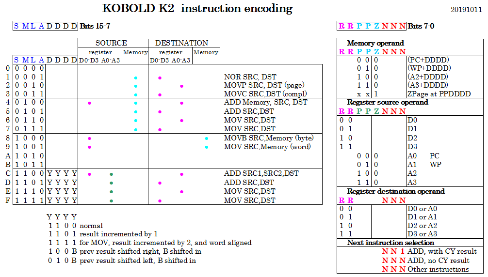
An instruction is 16 bits. The upper 8 bits are in the left part of the picture, and the lower 8 bits are in the right part. The upper 4 bits control almost directly the data path, and the other bits set displacement and register numbers.
CONDITIONAL BRANCHING
The CPU only supports branching on carry set. To be more precise, EVERY ADD instruction will do a branch on carry.
The branch must be within the same instruction block, and the branch target is the next slot as defined in NNN, but with the lowest bit set to one.
So what if we don't want to branch at all ? Then we put the next instruction in a slot with an odd number. If now the carry gets set, it will make the lowest bit of the next slot number one. But it is already one, so it will go to the same instruction, whatever the carry bit may be.
And what if we want to branch on NO-carry ? We simple change the positions of 'normal' next instruction and the jump target. This is possible, because instructions can be in any position within a block.
Note that jump-on-carry can also be used to test for zero. Just add 0xFFFF to the value that you want to test. If there is a carry, the value was not zero. The constant 0xFFFF will not cost us space for an immediate variable if we put it in the zero page space.
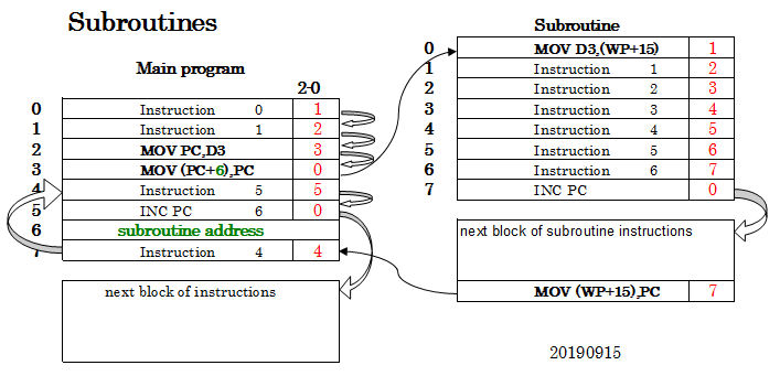
[ edit: the contents of this log does no longer reflect the operation of the Kobold K2. So it is for amusement only.]This is the instruction sequence for subroutines:
In slot 2, save the program counter to the D3 register
In slot 3, load the program counter with the subroutine address (found in slot6, shown in GREEN)
The subroutine is executed now. The first instruction saves the return address, that was stored in D3, in the workspace at slot 15.
When the subroutine has finished, the program counter is loaded with the saved program counter and execution continues at slot 7 in the main program.
Back in the main program, instruction 4 is executed, followed by instruction 5 and then a jump to the next block.
By convention, the slot to return to is always slot 7.
In most cases (but not in this example), the subroutine will also create its own "stack frame" by using a new value for the workspace pointer WP. This makes nested and recursive functions easy.
In this example, the call instruction is in slot 2 and 3. But it can of course also be placed in other slots. Note that this mechanism utilizes the possibility to put instructions in any order that you want.
ADDRESSING WITHIN 256K RETURN LOCATIONS WITH ONLY 16 BITS
The program counter has 16 bits, where bit zero is always 0 because instructions are only on even addresses. Each value in the PC addresses a sequence of 8 instructions. So the maximum number of instructions that can be addressed is 262144.
For the return address, only 16 bits have to be stored. The drawback is that within an 8-instruction block there can only be one subroutine call, because the return point is always in slot 7.
[ edit: The addressing and sequencing of instructions as presented here is rather unusual. However, for the Kobold K2 this has now changed to a more usual system, so this log is now mainly for amusement.]
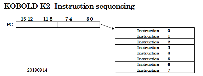
In the previous log I stated that the program counter uses the object model. A simple picture will make this clear:
This shows how the program counter points to a block of eight instructions (This could be a block of sixteen instructions, but for various reasons eight is used). We call these eight instruction positions 'slots'.
Every instruction is 16 bits wide.
All the instructions will be executed, and then the CPU will continue with a next block of instructions. How ?
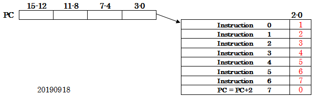
Within every instruction, the lowest three bits contain the slot number of the following instruction that must be executed (indicated in RED). It acts as a kind of counter. In the seventh slot, the slot number of the following instruction is 0 again. But the instruction in that slot increments the PC, so the CPU will continue with the next block of instructions. The PC-increment is just a regular CPU instruction. No extra hardware needed for that. (Note that the PC must be incremented by 2 each time, because instructions are at word addresses.)
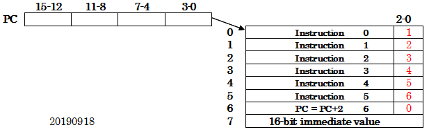
This makes it easy to support immediate operands. The instruction that uses an immediate operand, specifies the PC as pointer and uses the slot number (here: 7) as displacement:
Several instructions in the same block can have an immediate operand, as long as you use a different slot number for every immediate value.
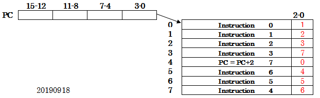
Get used to all the tricks that can be done ! For instance, there is no need to put the instructions in sequence:
In this example, the first four instructions are placed in the first four slot numbers. But at instruction 3, the instruction tells us that the following instruction is in slot 7 !
So instruction number four is in slot 7. The following instructions are placed in preceding slots. The last one is placed in slot 4.
Actually, you can place instructions in any order that you want, as long as each instruction points to the next one. (But by convention, the first instruction is in slot 0.)
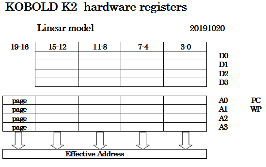
This 16 bit processor has a 20 bit address bus. How is this address generated ?
Around 40 years ago, developers of the Intel 8086 were facing the same problem. This time, we will use an easier solution. But I doubt if my solution will be more successful.
In the Kobold K2, memory can be accessed with the following addressing modes:
ADDRESS REGISTER INDIRECT
Each of the four address registers has its own 4-bit page register. A page register can be written with a MOVP instruction.
The memory address consists of bit 0-15 coming from the address register and bit 16-19 coming from the corresponding page register.
In instructions that use this mode, the displacement should be set to zero.
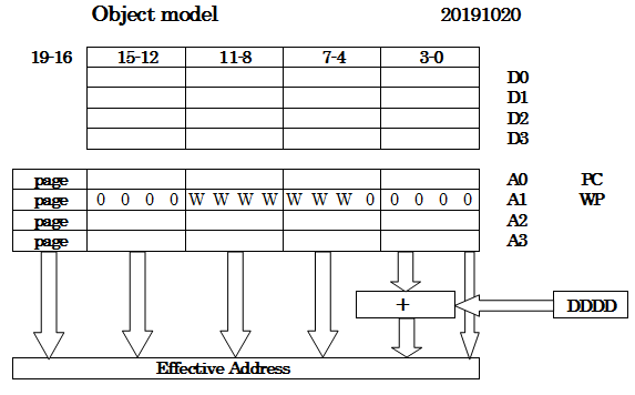
INDIRECT WITH DISPLACEMENT
This is considered the main addressing mode. In this mode, the 4-bit displacement value in the instruction is added to bit 1 - 4 of the address. There is no carry from bit 4 to higher bits.
In C terms, the address register can contain a pointer to many different structure instances. Each structure has a maximum of 16 word-sized members. The instruction can specify which member is addressed. This supports the "->" operator in a single instruction.
Register A1 is intended to be used as 'workspace pointer', pointing to a set of 16 locations that can be used as local variables in a function. When a function is called, the workspace pointer can be set to a new value to get a fresh set of variables, so it is not needed to push the old ones on a stack one by one.
As you can see in the picture, there can be seven W bits to define the workspace so 128 sets of registers are available.
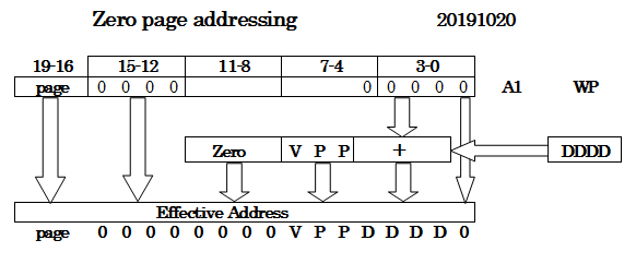
ZERO PAGE ADDRESSING
There is also absolute addressing. Only short addresses, that are a part of the 16-bit instruction, are supported. It is called Zero page addressing because the upper part of the address is always zero. The instruction delivers the bits VPPDDDD, for a range of 128 locations. Note that this mode also uses the value of several workspace pointer bits.
WORD OR BYTE ACCESS
The K2 is designed as a 16 bit processor that reads or writes 16 bits from/to memory at the same time.
In order not to exclude languages like C, support for 8-bit characters was added. Therefore, the K2 can address bytes or words in memory. The address in bit 0-15 is a byte address, so for accessing words, addressbit A0 is always zero.
For 8-bit instructions that read or write memory, the lowest address bit determines if the low or high byte in memory is used. The K2 is little-endian.
However, to keep component count reasonable, a little software effort will be needed to read or write bytes:
When reading a byte, the low byte will always be the requested byte, but the high byte will in most cases not be zero. To be more precise, for memory-read actions there is no difference for byte- or word instructions. When A0=0, reading the low byte is done in exactly the same way as reading a word. when A0=1, the high byte is copied to the low byte but the high byte is not set to zero. So it might be needed to AND the result with 0x00FF. Since there is no AND instruction, read it into a data register with MOVC (move complement) and then do NOR 0xFF00 to get the same result.
There is a special MOVB instruction to write a byte to memory. The hardware will write only the low or high byte, depending on A0. But when writing, a word should be written with the high byte being equal to the low byte. This could be done with a simple look-up table with 256 locations.
Note that the processor registers will always contain words.
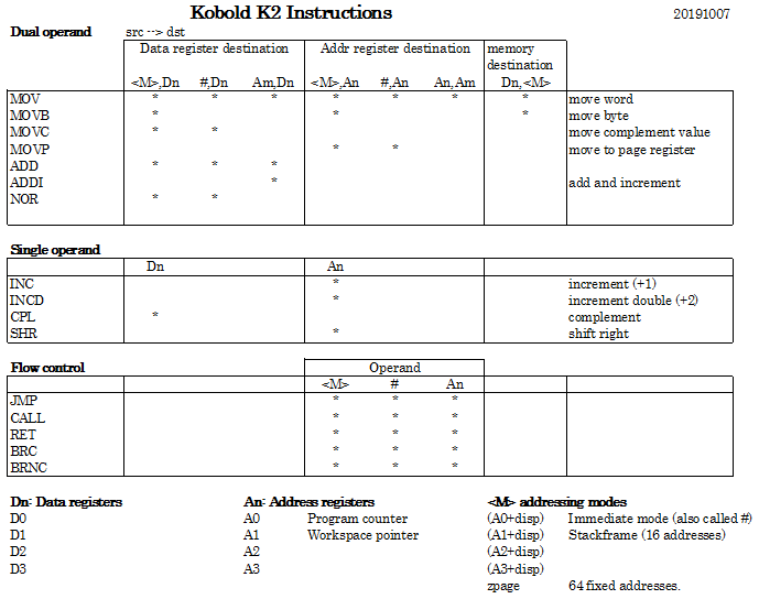
This is the envisioned instruction set. It is not complete, several instructions have to be added.
Several things that are possible, are not in the overview. For instance, there is no INC for a data register but it can be incremented by adding #1 to it. Logical OR and AND are possible by combination of CPL and NOR instructions.
For subtracting, one of the operands must be complemented (CPL) and then incremented (INC) to obtain the 2-complement, and then both operands must be added (ADD). There is a ADDI (add and increment) available, so the INC and ADD can be a single instruction.
A jump is a MOV to the program counter (A0). To do a call, you must store the programcounter (in a data register) and then do a jump (exact call system to be discussed later).
[ edit 20230125 more accurate drawings and more explanation ]
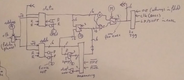
Main parts are:
4 data registers D0 - D3 (16 bit)
4 address registers A0 - A3 (20 bit)
16 bit ALU that can do only ADD and NOR
shift unit that can shift one position to the right
instruction register
Single memory for program and data
Every instruction needs two cycles:
EXECUTE CYCLE
This will let the ALU calculate a new value and put this in the shift unit. Or it will store a data register in memory.
The inputs for the ALU are:
a data register and a memory operand, or
a data register and an address register
a data register and a short 8-bit immediate
For memory operands, the address comes from an address register and displacement, or it is a zero-page address. 16 bit immediate operands can be selected by using the program counter as address register (and using a displacement).
Most of the parts in the CPU are directly controlled by bits in the instruction register, just as in the Data General NOVA whose instruction set is found HERE.
FETCH CYCLE
The contents of the shift unit is transferred to the destination register. The contents can be either shifted or unshifted. The PC (address register A0) is connected to the memory address. The next instruction is fetched from memory and is put in the instruction register.
Incrementing the PC will be discussed later.
DATA FLOW FOR MAIN INSTRUCTION TYPES
This shows how data from memory is added to a data register.
The 4-bit displacement (coming from the instruction) is added to the selected address register to form the address. (Displacements are added to bit1 - bit4 and the address register contents must be aligned). In zero page mode, the address comes from the lower byte of the instruction.
The ALU can do a ADD or NOR operation. The result of an operation goes to a data or address register. By making combinations, the following other functions can be obtained:
MOV: The ALU can transfer the memory data to a register without change. This is done by forcing the data register output to zero and set the ALU operation to ADD.
COM: A register can be bitwise complemented by NOR'ing it with the value #0.
SUBTRACT: First complement one of the operands. Then do the ADD and finally ADD #1. Both ADD instructions can be done by a single ADDI (Add and increment) instruction.
OR: Do a NOR followed by complement-register
AND: First complement both operands, then do NOR
JMP: The program counter is in A0, so a jump is just a MOV to A0.
Complementing a value (bitwise) is often used in this architecture, because it is needed for subtract and for most logical operations. It can be combined with MOV to a single instruction:
MOVC: MOV and Complement. The ALU can bitwise complement the memory data and transfer it to a register. This is done by forcing the data register output to zero and set the ALU operation to NOR.
The NOR operation is only possible when the destination is a data register.
The same instructions can be done when the operand comes from an address register instead of from memory.
MOV: The ALU can transfer addressregister+displacement to a register. This is done by forcing the data register output to zero and set the ALU operation to ADD. (The carry-output of the 4-bit displacement adder is routed to the main ALU where it is added to the result. So there is no need for alignment of the address register contents). This setup is used to add a small number to an address register.
BRC / BRNC: Every MOV instruction can be conditional. A small number can conditionally be added to register A0 (the PC), providing conditional branches. The assembler generates long jumps but will use a near branch if possible (Long jumps can also be conditional).
ADD: An address register can be added to any data register. A data register can also be added to an address register, but in this case the number of the source data register must be the same as the number of the destination address register. So ADD D2,A2 is possible but ADD D2,A3 is not possible.
MOV: A data register can be moved to an address register by setting the zpage-address to zero and set the ALU to ADD. This will add 0 to the data register and put the result in the address register. The number of the source data register must be the same as the number of the destination address register. So MOV D2,A2 is possible but MOV D2,A3 is not possible. Of course, you can also add a small number in the same instruction by using a non-zero zpage-address.
This picture also shows that a Zpage address can be routed directly to the ALU. This provides the 8-bit immediate operand mode. This immediate mode can be used with all main instructions: MOV, MOVC, ADD, NOR.
Finally, storing a data register is straightforward. There are instructions for store-word and store-byte. An address register can be stored by first moving it to a data register.
Note that the output of the ALU is also written back to the stored register (not shown here) because this effect is not suppressed in the current version. Since the data register contents is present on both ALU inputs, the dataregister will be added to itself. This is used in the SHL (shift left) instruction.
Several topics will be discussed later:
incrementing the PC
carry handling
subroutines
loading the upper 4 bits of address registers
I can already uncover a bit more by showing my nice drawing (it is from an early version and no longer accurate):
 This is the instruction sequence for subroutines: