Twice in the last couple of years I have needed a probe to diagnose problems with a non-isolated power supply that connected directly with the 125VAC mains voltage here in the USA. I have been able to work around it by using less than satisfying methods. My cheap oscilloscope (a Rigol DS1102E) is good enough for most of my purposes, but the math function to subtract Channel 1 from Channel 2 really sucks. And even though it is a cheap scope, I'd rather not have to buy a new (more expensive) scope because I connected the scope ground incorrectly.
Needing a tool on a yearly basis hardly qualifies as necessary, but I had some down time waiting for components and PCBs for another project and began to consider this as an interesting project.
There are now three versions of this probe. My original version that is powered by a 5VDC adapter, Paul's new version is powered by any adapter in the range of 7-12VDC, and a 1X version -- see Christoph's Project. Paul made some changes to increase the creep distance between the input pins since he needs to use it with 240VAC mains. You can find the Gerber files, BOM and schematics for Paul's version on his Github Page. Christoph's 1X probe uses my design, but changes the attenuator to achieve higher differential gain at the expense of lower common mode range.
I'd been following Paul Versteeg's progress to make a differential probe on his blog. I recommend that you read it -- he covers most of the basics and has some good references of other approaches to make this kind of probe. Paul has done more thorough testing as well (his equipment is better than mine.) He also spent a lot more effort explaining how to assemble the probe and calibrate it. There are also several persons within Hackaday that have completed projects successfully, or are still ongoing.
The Specifications:
- Input impedance: 20MegΩ// 1.25pF - differential, 10MegΩ//2.5pF each terminal to GND.
- Differential Gain = 1/10 V/V. Any lower than this and the DS1102E could not resolve a 1V signal with any clarity. (Many of the cheaper differential probes are switchable between 50X and 500X attenuation. This would be good if the signals in which you are interested are very large, but that's not the case so far with my needs. The better probes ($400 and up) provide 10X/100X attenuation.
- Common Mode Range > ±340V (240VAC produces a sine wave 679V peak-peak)
- CMRR >90dB @ DC, ~60dB @ 1MHz
- Differential Voltage Range > ±24V for 240VAC common-mode, ±24V for 0V common-mode (Paul's version increases both ranges to ±25V)
- Bandwidth ≥ 100MHz (Dependent upon signal amplitude) This will be a stretch for my current skill set.
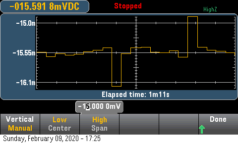
- DC offset < 20mV
- Noise: 2.2mVrms at output.
- Cost: ~ $50
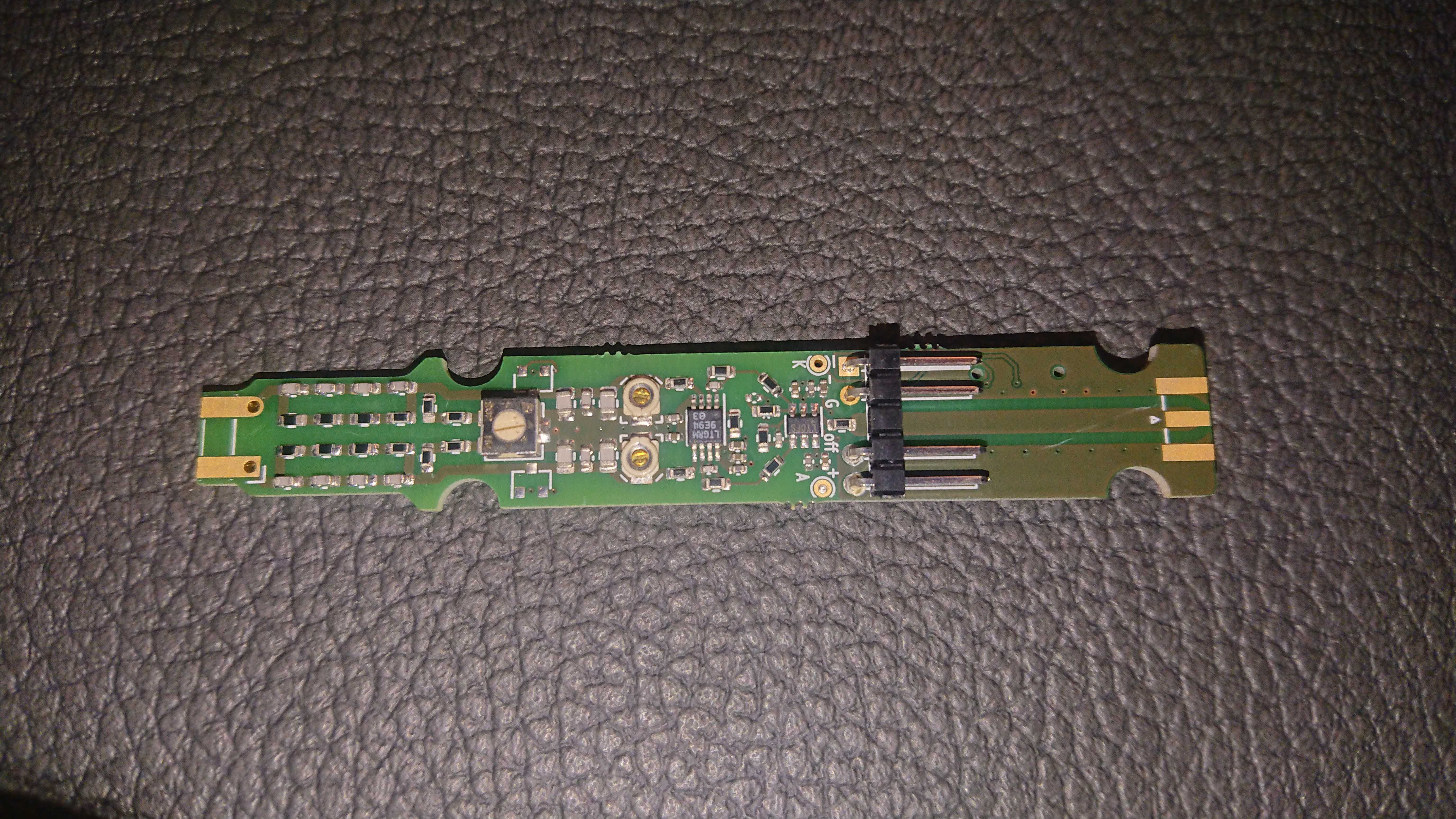
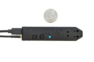
The completed probe:
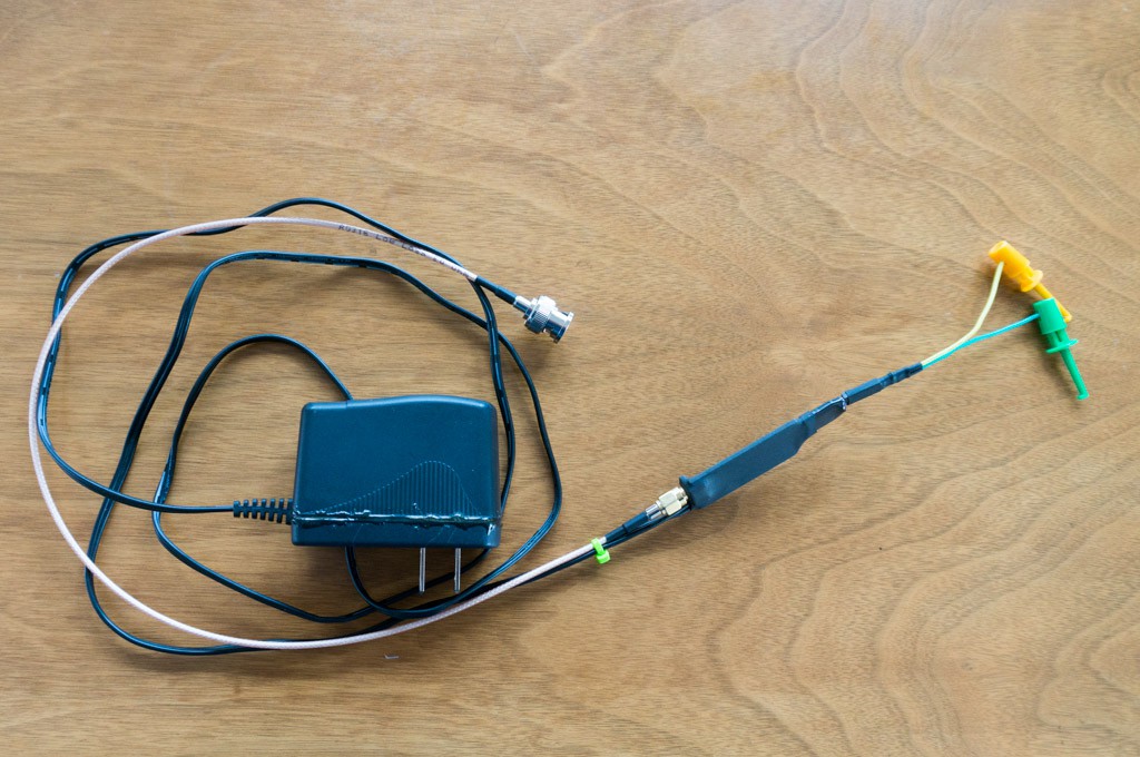
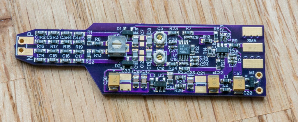
The above photo is my completed probe. You will need a 5VDC adapter to power Bud's probe or a 7-12VDC adapter to power Paul's probe, and a SMA to BNC pigtail to connect the probe to the scope. You should also consider making a few leads for various situations. The leads use a Dupont 0.1" (2.54mm) 2-pin female connector to attach to the probe. The green tie-wrap provides a bit of strain relief for the power supply leads into the probe.
The Schematics:
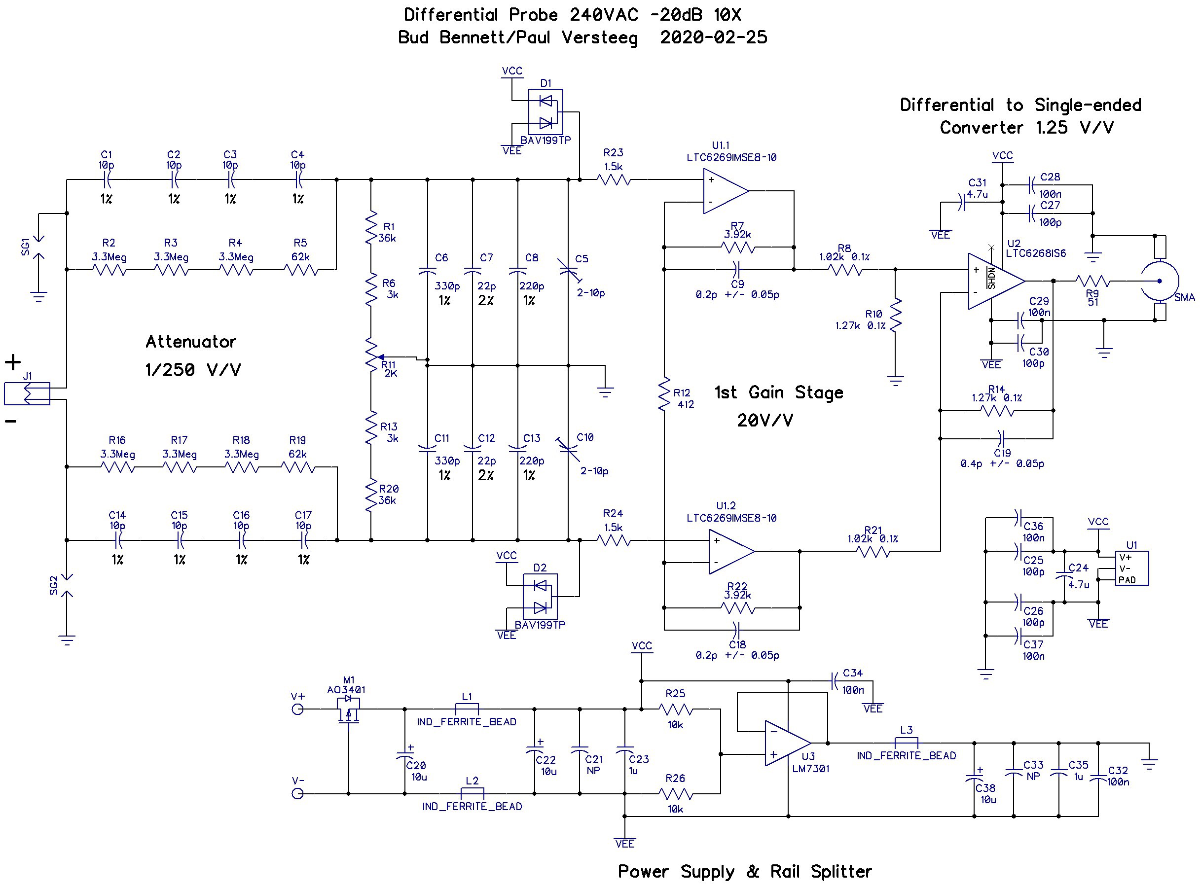
There are now two versions of this probe.
The 5V adapter version (Bud's):
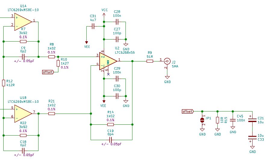
The 7-12V adapter version (Paul's):
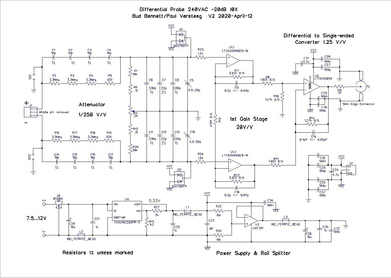
[Edit 2020-01-30: Improved the differential range with a 240VAC input to ±24V with small changes to component values. No change to the PCB layout.]
[Edit 2020-02-05: More conservative design for the first gain stage stability. Replaced BAV99 diodes with BAV199.]
[Edit 2020-02-13: Increased R23 and R24 to 1.5k from 510Ω to reduce ringing with fast input step.]
[Edit 2020-02-25: Changed C6-C8 and C11-C13 to match lower capacitance of the 10pF input capacitors. Your mileage may vary.]
[Edit 2020-05-10: Changed C19 to 0.4pF±0.05pF to match Paul's schematic. He found the bandwidth not quite 100MHz so reducing this...
Read more » Bud Bennett
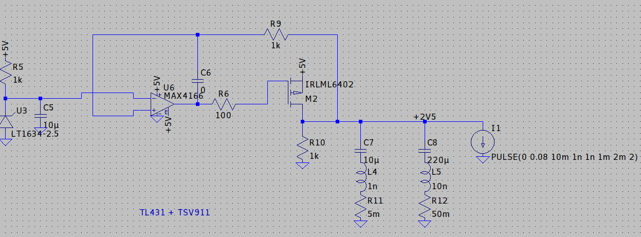
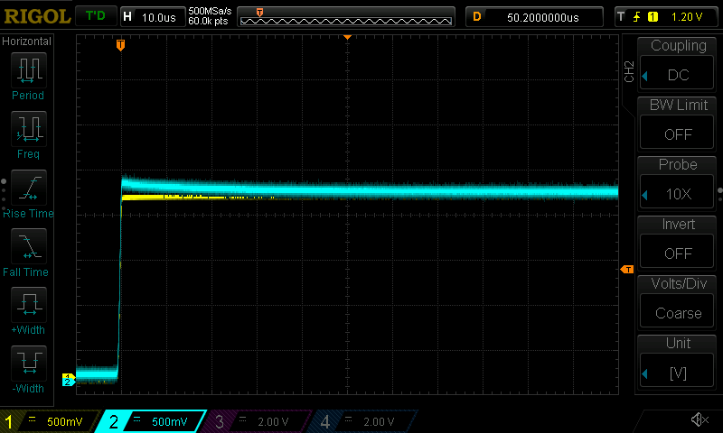
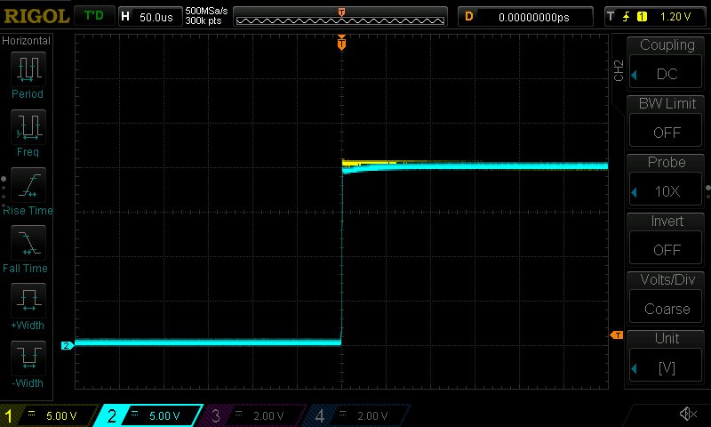
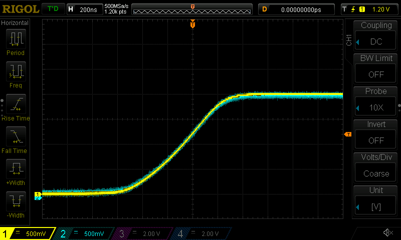


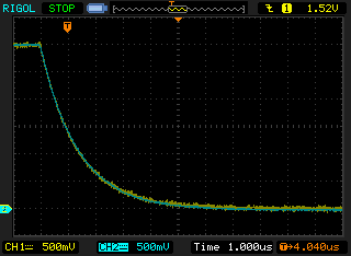
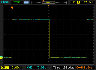
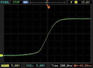
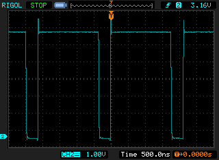
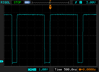
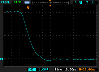
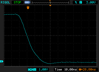
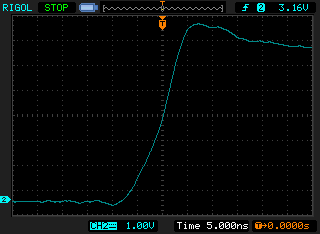
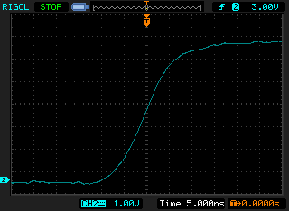
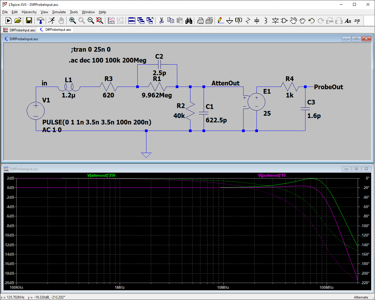 A small value of series resistance in the lead will remove most of the ringing caused by the lead inductance. The largest value of series resistance that can be inserted into a 3 inch long lead is 620Ω. Any more than that will reduce the bandwidth of the differential probe. There is also a small, 0.006%, reduction in gain.
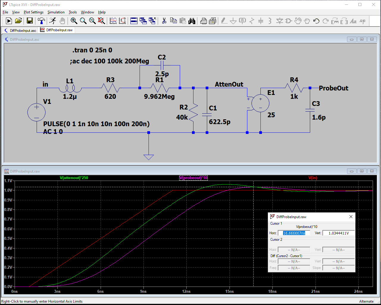
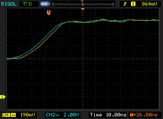
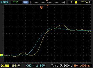
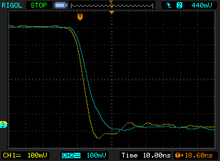
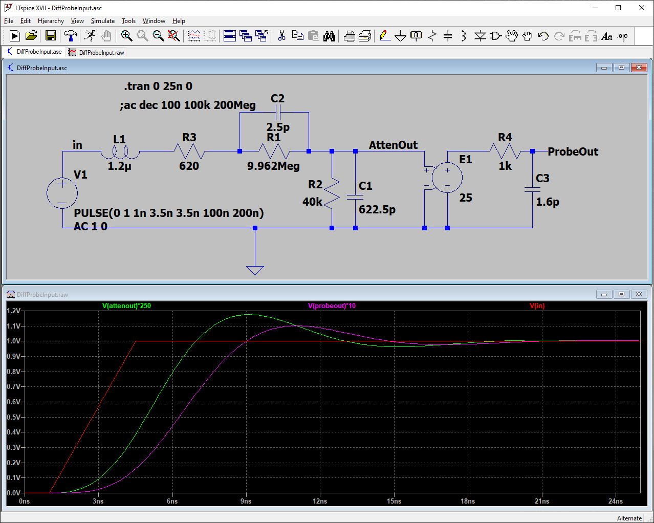 There is a 10% overshoot in the probe's response to this fast step. Clearly, if you need fidelity on signals with very fast rising edges the lead length must be as small as possible. But if the rise time is reduced to 10ns the overshoot decreases to only 3.5%:




 Christoph
 michal777
 Petteri Aimonen
Hi Bud,
I made one of these a while back and it works well, using Paul's version of the design. Testing it on my HP4396B VNA, I see a dip in s21 (through response) of about -6dB at around 35MHz. I believe its due to the parasitic capacitance coupling between the two input divider chains, which are quite close together. The series inductance of the resistor chain and the parasitic capacitance between them are the likely cause.
Commercial probes like the MicSig one space the two divider chains out, to the extent of making the PCB U-shaped to minimise the coupling capacitance. I wonder if it's worth trying a new PCB layout to test the theory out.
BTW, apart from that dip the frequency response is pretty good (i.e. within 3dB) out to about 250MHz .
Keith