 John Lonergan
There were various motivations for building this:
- To test a bunch of chips I bought from eBay and AliExpress
- To allow me to check my understanding of the functioning of certain interesting and rarely mentioned logic chips.
- To learn something about Arduinos
- To learn about EasyEda
- To have some fun getting a PCB made up (not having to etch it myself like the old days)
- Nostalgia - I built something with a similar function at university in 1984 but it was a much bigger physically and hooked up to a BBC PC.
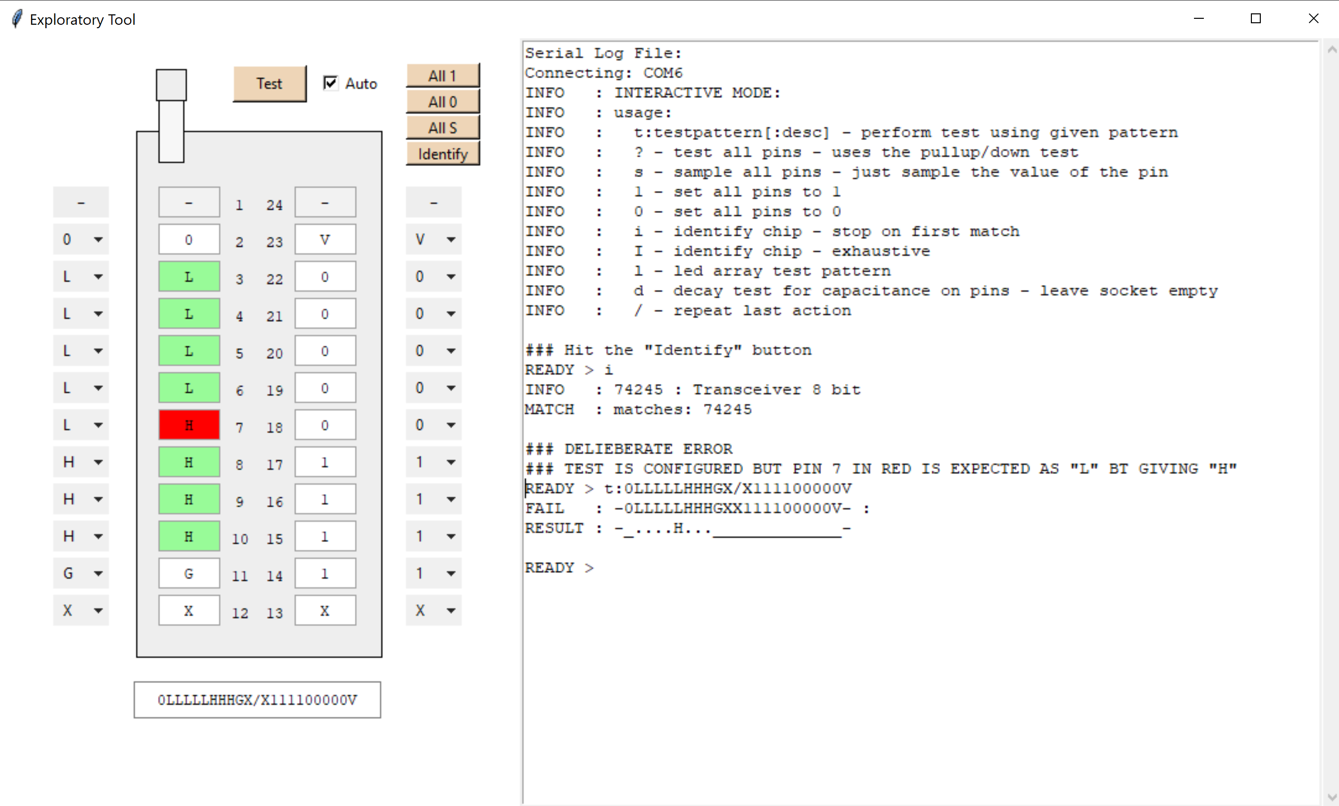
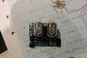
This was not intended to be a chip identification tool as I can read that off the top of the device, but more about testing and learning.
Full details can be found on...
- github - https://github.com/Johnlon/integrated-circuit-tester/blob/master/README.md
- easyeda - https://easyeda.com/john.lonergan.sharing/integrated-circuit-tester


 Johnny
 Anders Helgesson
 Hulk
Hulk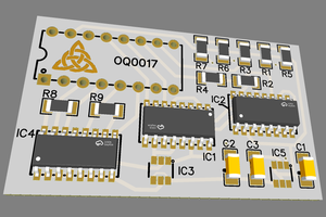
 macafeeje
Sorry - missed this comment. Do you mean 74LS
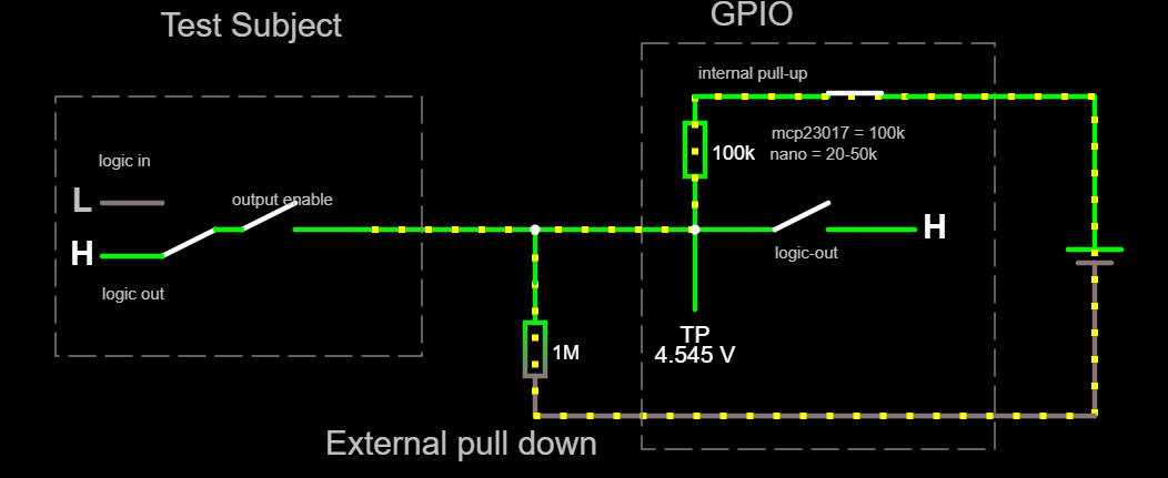
The GPIO chips I use almost certainly source enough current to properly pull up the inputs of 74LS.
You would need to supply the chip under test with 5v in isolation from the rest of the board. You don't want everything else lighting up as the tester needs to be in sole control of your device. In practice that means either lifting the VCC leg of the chip or cutting the leg so that you can power it independently of the rest of the card.
I use MCP23017 so you could check it's output voltages and source/sink currents to see if it would drive the 74 chip's inputs.
Output high is VDD – 0.7v
Output low is 0.6v
Max current per pin 25mA.
Should be good to LS logic levels I think as long as fan out isn't crazy.