-
Bipolar Capacitor Bucket Brigade
01/27/2021 at 01:41 • 5 commentsSometimes, all you need to know is the right term to enquire Google.
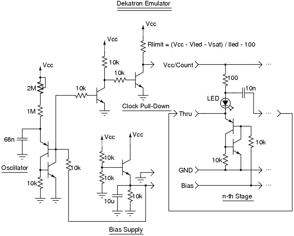
So I was browsing here and there before I noticed that what I want to do is almost like a Dekatron, but where more than one element can be active at a time. Then I found Alan Yate's Dekatron Emulator.
![]()
It's nice though I haven't found yet how to coerce the chain to allow more than one bit set at the same time. But he muses thusly :
A micro-controller could clock different patterns into the ring and could control resetting it - reset logic is important for using as a real counter and would need to ensure the "0" cell fires alone on reset, in the practical circuit one cell will dominate on first power-up and clocking but it would need to be a formalised reset for counter use. With buffering the adjacent-cell problem could be removed and you'd have a bucket-brigade or delay line memory which might be useful for some applications.
Then it was obvious that the shift register I want to make is a delay line, or a bucket-brigade of capacitors, or a glorified CCD line. These are still pretty common in niche applications, such as sound delay lines but mostly they use MOS transistors.
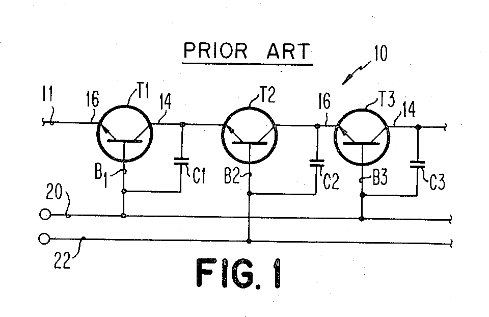
Some more googling with the enhanced keywords ("capacitor bucket brigade shift register bipolar" is a mouthful that yields 1 260 000 result) and I find what I didn't hope to see, in the patent US3796928A filed in 1971. The prior art contains this schematic :
![]()
I don't see how this could be simpler. There are 2 transistors and 2 capacitors per "position" and the complexity is moved to a 4-phase driver. I also like that all the transistors are of the same type. However the retention time is quite low but this should be sufficient for a serial transmission. I'll have to find tricks for holding the value into buffers, which is also a very interesting problem for #Clockwork germanium.
This circuit would work nicely with modern (low-leakage) silicon transistors but a recent log (18. More characterisation) found that Germanium has a quite low breakdown voltage between base and emitter. This would limit the range to about 2V, otherwise the data could flow backwards...
I also hope that circuitjs will not explode during the simulations like it does when I use the SCR PNP-NPN topology...
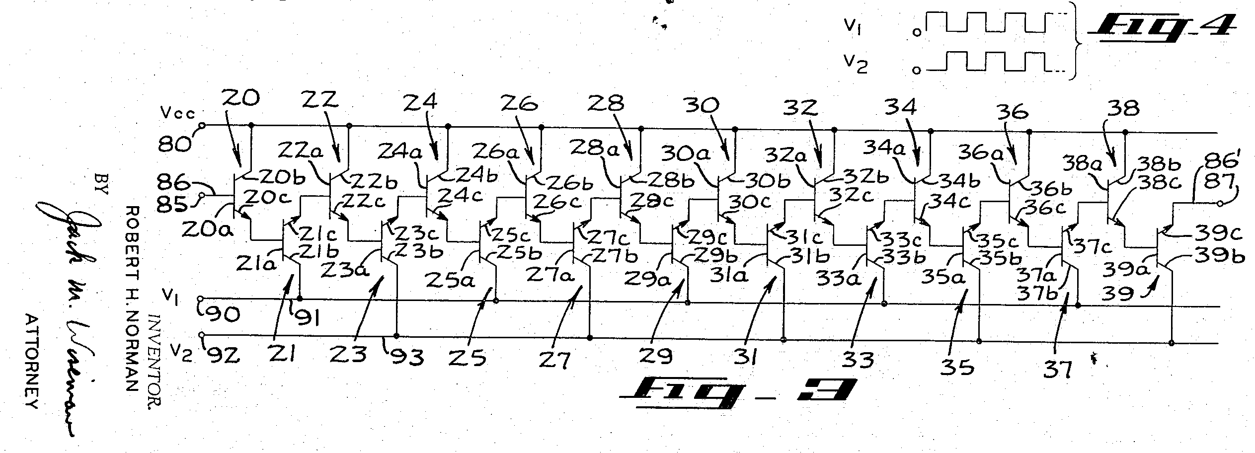
A related (expired) patent filed in 1969 :
US3671771 : A charge amplifier for a bucket brigade capacitor store
![]()
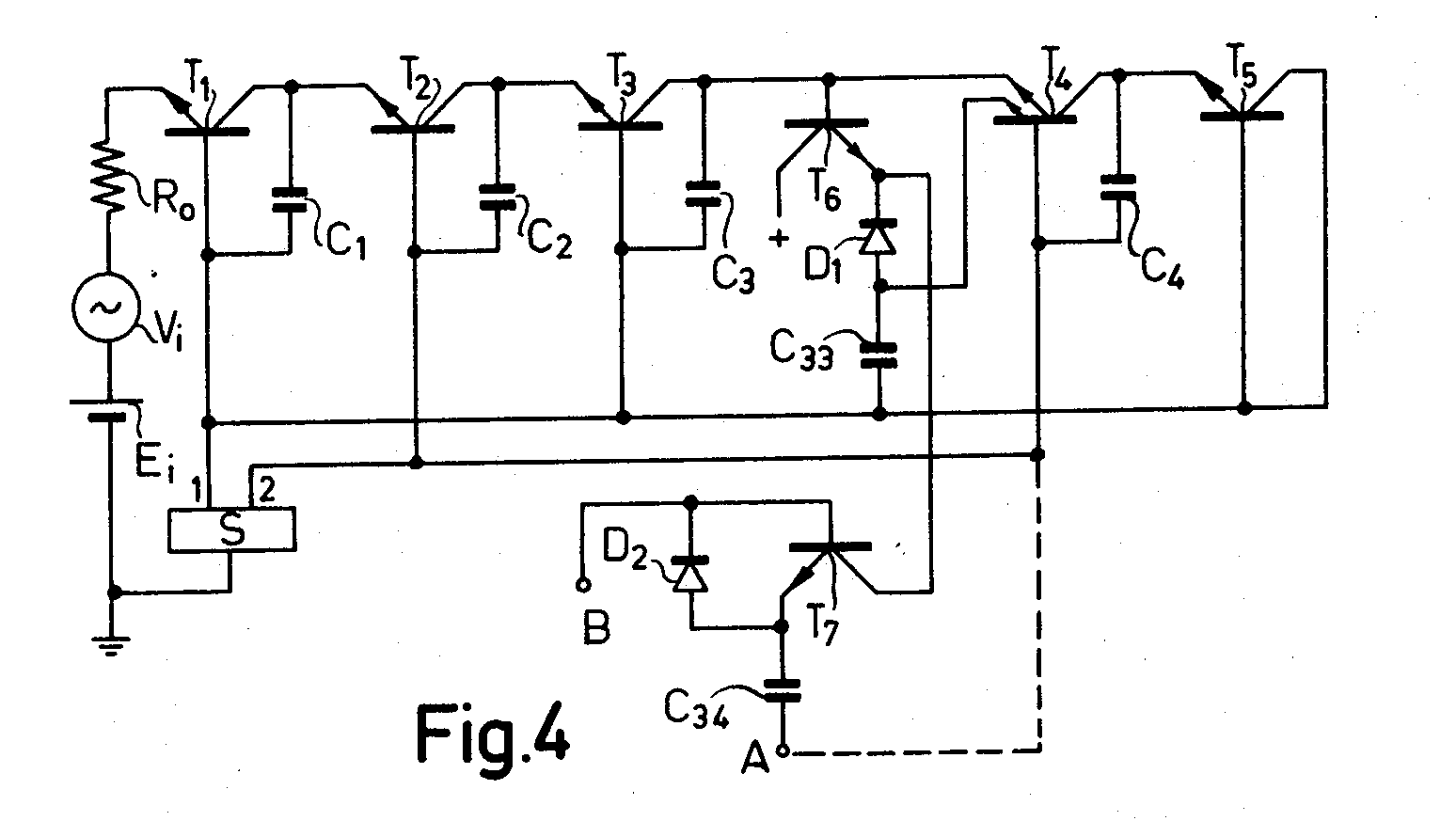
And back in 1964 this strange circuit was filed :
![]()
And now I need a generator of non-overlapping pulses.
For discrete and leaky implementations, with old transistors and medium speed shifting, a mixed approach could work : 2 "basic" stages (2T+2C) followed by another T for buffering, like the above diagram. That's 3T per bit, and there might even be a way to select where the data would be sent (either the next bucket in the line, or the output buffer).
-
An even better SCR-based sequencer
04/13/2020 at 01:05 • 2 commentsI felt that my method was not optimal but I was OK with it, by lack of a better system.
Then the HaD blog published this video :
The digits counter use a SCR-based circuit that uses one complementary pair per output.
It is very reminiscent of the Dekatron system, but with transistors instead of gas discharge tubes !
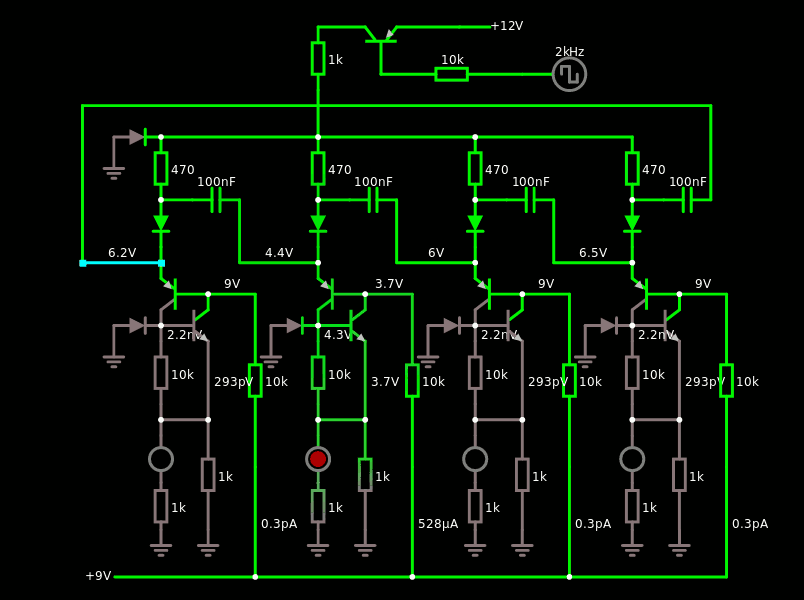
I have reproduced the circuit with Falstad's sim:
![]()
And here is the simulation. Don't mind the diodes to GND, they only help with preventing the sim to explode when the bias is too weird (no idea why).
That bias is a really, really surprising artefact that I had not seen before... yet. Its value is "somewhat" important, between maybe 8V and 11V. I'll have to investigate and it might explain why my previous SCR-based circuit failed.
It's genius because it simplifies my more convoluted circuit.
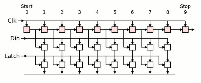
There is a big difference though : this pseudo-dekatron is synchronous to a fixed clock, and not self-timed. But this further simplifies my new idea because now, the RX is fully synchronous and shares a common input... The dekatron will steer the (buffered) input to one of the 8 latches, while also working as the state of a one-hot FSM.
![]()
The "pseudo-dekatron" (top row) receives the clock that lets a pulse propagate from the state 0 to state 9.
The buffered input data is latched by either one of the 8 transparent latches, one by one.
The output buffer is finally latched, all at once, when the whole word has been correctly loaded.
The cost : 2 (P+N) for the pseudo-dekatron bit, 3 per latch (2 FF+1write enable), so 8T/bit, 64+4 T for the whole datapath.
The Dekatron-like circuit is also great for the frequency predividers !
-
Tx with fewer parts
03/11/2020 at 06:32 • 0 commentsThe FlipFlops use a significant amount of parts so the fewer, the better !
There is not much to do for the receive part but the emitter could get a little fewer latches. The initial design uses 3 latches per bit, or 24 latches (72 transistors overall). 8 latches are required for the emit buffer anyway (24T). Using a Johnson counter can create the semi-decoded system, with 5 stages or 10 states, one for each bit as well as the start and stop bits.
A binary counter would not save much because that would require 4 latches, not far from 5, and the binary decoder uses gates as well : I have covered binary selectors (MUX trees) at From XOR to MUX already and each bit requires 3 transistors in average. So it's roughly equivalent (though less delicate than Flip Flops)...
The 10 outputs of the Johnson counter will directly select one bit to output (there would be 8 ANDs and a big OR) and the Johnson counter would use the technique explained at Reduction by mirroring: the clock pulse ripples through RC cells to trigger successive pulses. This saves transistors because there is no need of a Master/Slave duplicated configuration. That's 4T per bit, or 20 for a 5-stages Johnson counter. Total (for the datapath) : 20+24=44T (including 5 complementary). The big AND/OR is not counted... There might be a need for a latch at the output to prevent spurious pulses, because the ripple will be nasty...
Oh and I recently heard about http://www.6502.org/users/dieter/uart/ :-)
Tx is "simpler" because it doesn't require synchronisation with the receiver so it's easier to start with.
-
Canned oscillator
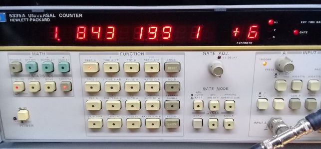
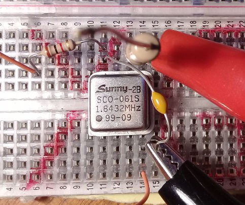
03/08/2020 at 22:21 • 0 commentsAmong the crystals I received, there is a couple of 1.8432 MHz integrated oscillators and I put them to the test today. The power is quite low : 2mW !
* The operating voltage looks pretty low : 2V !
* The operating current is just about 1mA.I can pull/push the frequency with :
- adjusting the voltage : lower voltage => higher frequency
- adjusting the output load : tbd
- temperature : tbd
![]()
![]()
From the start it's working at a few Hz away from the expected/rated frequency and it's great. An integrated CMOS or TTL frequency divider would provide all the needed operating frequencies.
-
Frequency sources épisode deux
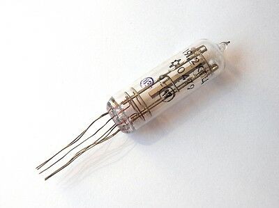
03/03/2020 at 21:31 • 0 commentsSo I received the quartz tubes and I'm characterizing them :-)
The 2-transistors circuit mentioned earlier works like a charm. The GS507 from @jaromir.sukuba flies without effort.
There is one tube marked as 2400Hz on the box but with no marking on the tube itself and I just measured it a 2402,4 Hz. I don't see how to center it better to 2400 precisely, as temperature and supply voltage don't affect the frequency enough.
I started playing with the liaison capacitor and it indeed has an effect but not the one expected : too low and it oscillates on 5th harmonic and sometimes more (11th harmonic ?). However this confirms what @SHAOS said about its importance.
I'm still playing with the circuit and it's a lot of fun, you can hear something like tinnitus if you hold the crystal to your ear and the driving strength is high enough. The oscillator can work down to a very low voltage, which is very fun to do with germanium :-D
I'm not overly concerned by the 1/1000th of frequency mismatch because it's still well below 1% required for serial communications and the other tube is clocked at 2403.1 Hz.
The quartz has a large inertia and can stand some power that would damage a wristwatch crystal. The output of the oscillator is strong enough to drive a simple amplifier. It's so fun to see a crystal that is more than 60 years old become part of a digital circuit ! However the circuit saturates a lot. Maybe the crystal is designed for a Pierce oscillator ?
I also tried the 19200 Hz quartz tubes from Ukraine (another great find on sr71's eBay shop) and they are easier to "pull" due to a different cut, probably, as well as 30 years younger. I find a 5Hz drift that is easier to remove by adjusting the feedback capacitance, it's only 1/5000 to correct instead of the much larger relative drift of the slower crystals.The OC139 drive it easily, even with swapped emitter & collector... It's fun that I can also pull the frequency by shining light on the black-tinted glass ;-) the paint is not perfectly opaque and now I understand why the metal cans have been a necessary evolution.
The GS507 seem to work well at 19K2Hz and the digital logic should work fast enough.
-
Frequency sources
02/24/2020 at 03:41 • 6 commentsAt first I was like "OK I will try to run at 115200 bauds" and then I realised tht the GBWP of certain transistors wouldn't allow that.
Anyway I started searching for 1.8432 MHz quartz crystals (I ordered some) and the first thing to do is to drop the frequency as much as possible, first by factors of 2-4-8-16 so more complex gates/circuits can be used at lower frequencies.
Then I encountered tiny 38.4KHz crystals on eBay : this won't provide much bandwidth but it is much more suitable for Germanium trannies. I don't mind that it won't run at 115200 bauds because it saves a lot of high frequency dividers... But we're only getting started !
These modern tiny crystals will come from China, someday, when/if the export problems (due to the virus epidemic) are solved. No such problem with Ukraine : our old friend bird_sr71a has some better resonators, at "only" 19200Hz ! In the worst case, if I have to divide by 2, I can still reach 9600 bauds, a pretty standard and useful frequency, though I'll see if/how I can keep up with 19.2kbps.
![]()
It's much more classy and more coherent with the rest of the technologies I'll deploy :-)
But we can go even further...
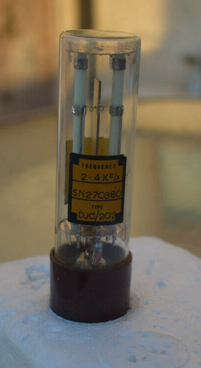
Closer to Paris, a British store offers European vintage crystals that are even older.
![]()
Now it's very, very slow... and I hope the OC70 will not complain ! Worst case will be 1200 bauds, which is still "pretty fast" if you were born in the 70s in France : the Minitel used 1200 bauds over POTS.
I'm expecting to receive a pair of these ultra-slow resonators, so there would be one for the send side and one for the receive side.
Driving these tubes would be easy with a pair of OC70 and the oscillator circuit that I discussed in the last log.
So I have a frequency source for a variety of transistor technologies :- OC70/OC139 "lazy germanium" in glass tubes -> 2.4Kbps would be good
- I have faster germanium transistors but very very few NPN for 19.2K
- KT315 & KT361 : silicon planar Russian complementary trannies : they could work at 38.4K easily. I hope.
- I have a very good supply of BC550/549 and BC559 and I hope they can manage to reach 115200 bps :-)
Anyway : I still lack tons of NPN germaniums. The price of the OC139/OC140/OC141 has skyrocketted due to the "DIY disto pedal frenzy", along with many others... I have ample supplies of OC70 but my minimal latch circuit requires NPN as well :-/
-
Oscillator mysteries
02/23/2020 at 02:41 • 0 commentsI think I cracked another mystery !
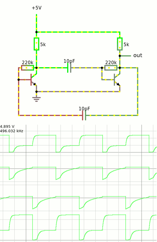
Thanks to Falstad :
![]()
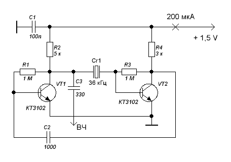
This is just the same circuit as this one (found there) :
![]()
It has been discussed at 12. It just works and 7. Crystal Oscillator (Germanium Edition) from some years ago. I had noticed that the value of C2 was meaningful and tuning R2 and R4 would affect the gain.
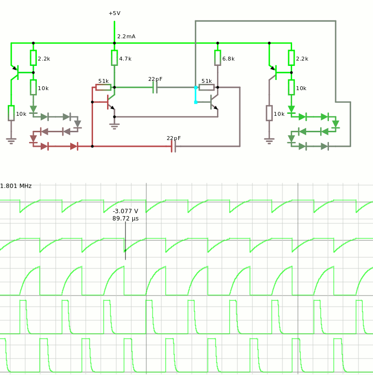
It is simply because, when one simplifies the crystal down to a capacitor, the whole circuit is just an equivalent to an astable multivibrator !
So the Rs and Cs need to be tuned to resonate around/at the expected frequency, then the crystal replaces one of the capacitors, and there you have it !
It started raising my suspicion that C2 was more important than I thought, when I saw some strange "motorboating" and the circuit would send a spike at regular intervals.
Usually I set C2 to a pretty large value because I considered it as a DC blocking capacitor that would feed the output signal back to the driver. But regularly, I would see spikes that would "shake" the crystal and change its operating conditions.
I thought it was a great thing because it would "kick" the crystal by itself, without manually snapping it with a finger. I would just have to find a suitable period, like, 10ms or such, to enable a fast startup. When the oscillation is settled, some other mechanism would prevent the LFO from "kicking in".
But if the whole circuit is tuned, the gain is much better and there is no need to periodically kick/pulse anything. Then the only question is : what is the equivalence capacitance of the crystal ? From there, t=RC and a crude value for the resistors can be found.
So yes @SHAOS you were right ! the value of C2 matters ;-)
The other nice thing is that it can generate "non overlapping pulses" that could drive the flip-flops. However the tuning of the capacitors makes it very frequency-dependent.
Here is the schematic at work :
![]()
The capacitors generate negative spikes (triangles) that can be sensed to drive the amplifiers on each side. The string of diodes as well as the series resistors 2.2K/10K help tune the width and overlap of the pulses shown at the bottom.
with ideal transistors and 22pf capacitors, the system reaches 1.8MHz in the simulator, which can be increased by reducing the base and collector resistors.
-
Baud generation
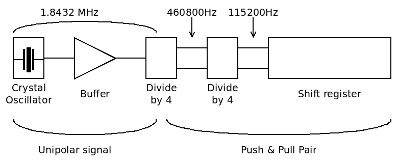
02/22/2020 at 05:48 • 0 commentsSupposing the whole shift register and the processor can sustain 115200bps, the clock generation looks like this :
![]()
It seems I can't find an oscillator slower than 1.8432MHz so I settle with that. I found an old large Xtal on eBay so the electronics will be deliciously weird. I'll use the circuit with 2 transistors shown atIt just works because it works indeed :-) However I have no idea of the impedance and other parameter of that laaarge crystal... I went through that study 4 years ago and logged everything so it will not be a serious problem.
The delicate part will be the buffer because my past experience with #Yet Another (Discrete) Clock shows that impedance matching is quite hard and even the 'scope can affect the very sensitive oscillator. Then that very weak signal must be amplified to a few milliamperes....
Then the signal goes through a modified unipolar div-by-4 cell. The input drives both PNP and NPN pass gates. The 2 outputs signals are then combined to create 2 non-overlapping pulses (code 01 and 10).
The non-overlapping pulses drive another NPN-only div-by-4. Again the outputs are combined into non-overlapping pulses to drive the shift register.
In theory it should work, right ?
Why do I use "div-by-4" cells instead of "div-by-2" ?There is no disadvantage to this choice, but a few notable advantages, in particular for the type of cells I use.
Complexity-wise, dividing by 4 or twice by 2 is the same : same number of parts (roughly) but the output is 2× slower, so it's better, and easier to turn into a pair of "non-overlapping signals" thanks to a pair of transistors in ANDN configuration.
-
Clock Driver
02/21/2020 at 01:07 • 0 commentsOne nasty part of this kind of design is to drive the pass gates with non overlapping pulses. Otherwise it's a terrible mess...
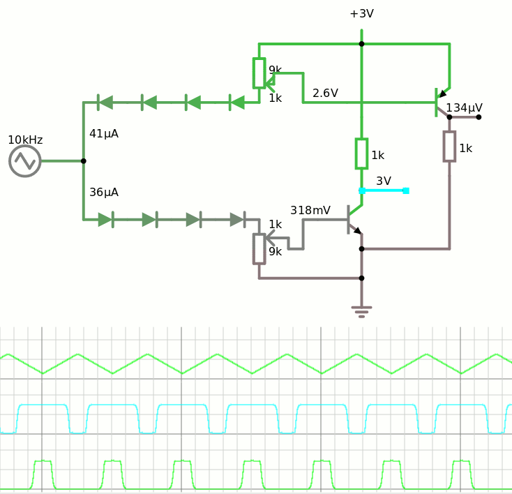
I have found this simple complementary driving system, using only a pair of transistors, and a bunch of diodes. The cool part is where the duty cycle (and pulse width) is determined by a potentiometer, and there is no capacitor in sight so it should work at medium speed without problem. The input signal is also supposed to have a slope...
![]()
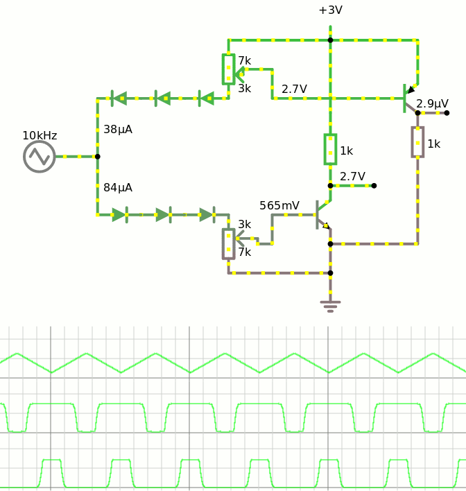
There is still some freedom in the choice of the number of diodes and the value of the potentiometers, though make sure that there are enough diodes to prevent a direct current from Vcc to GND ;-) At 3V the minimum would be 6 diodes.
The 1K pull resistor would be the actual load (2K2 resistors with each a BJT base and stuff).
I believe this driver would drive the first divide-by-4 cell. This cell would then output 2 non-complementary non-overlapping signals, suitable to drive the slower clocks. A divide-by-4 cell has 4 states and 2 BJT can detect two of the opposite states...
The version with 6 diodes works quite well too:
![]()
But now the shape of the input signal is the next critical problem.
-
First slice
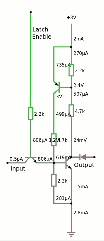
02/20/2020 at 23:08 • 0 commentsSo one latch "building block" is this :
![]()
BOM:
- 1 PNP
- 2 NPN
- 1 diode for the output (might be removed in certain cases, such as when driving another base)
- 3× 2K2
- 2× 4K7 (could be 2× 2K2 if needed)
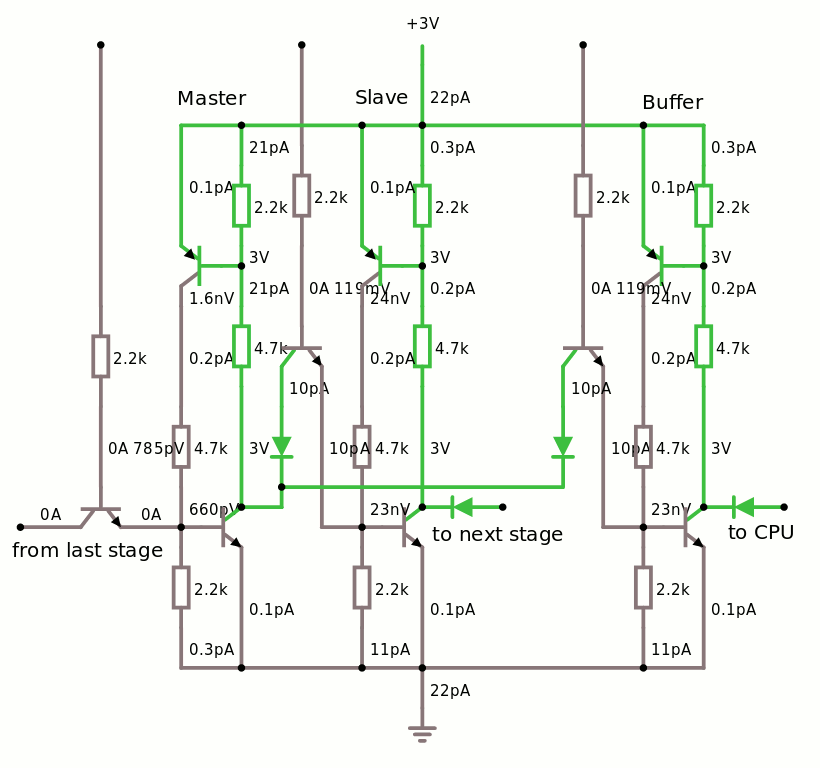
A "slice" is a "DFF and a half" : one master latch and two slaves, one of them can be connected to the processor.
![]()
This is pretty easy to place & route on a small board.
In this example, the "slice" is configured for the receive circuit (SIPO). The 3 latches must be connected differently to perform the PISO function, so each "slice board" would have each individual latch connected to the outside so a backplane can configure the correct function.
 Yann Guidon / YGDES