Paul Gould
-
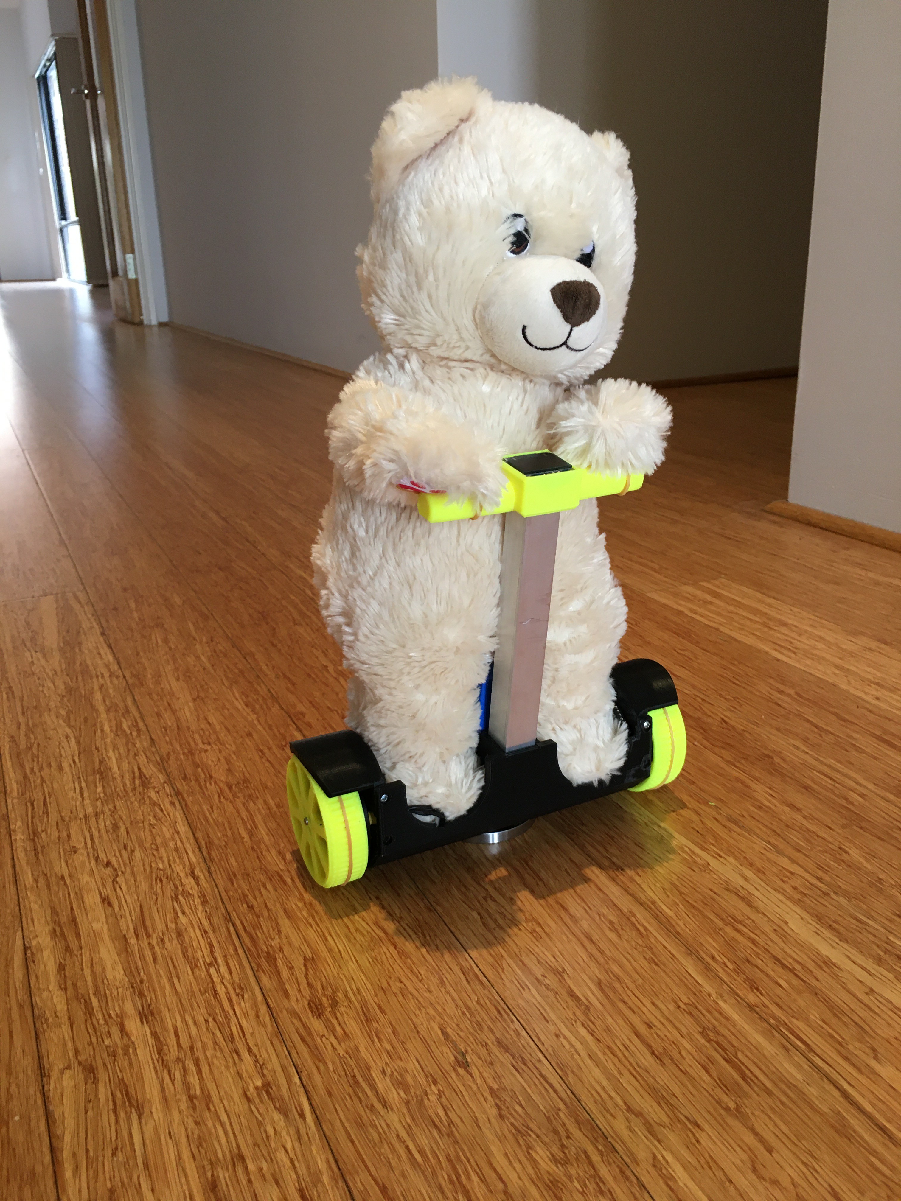
Teddy-Way / Hover-Teddy
05/10/2021 at 16:47 • 0 comments -
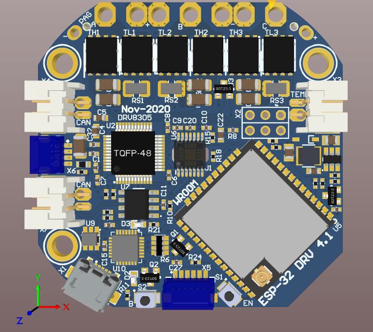
Revision 4_1
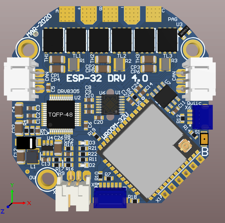
11/08/2020 at 13:52 • 0 commentsNow with onboard USB for Arduino Programming and diagnostics. 30A @ 30V (~1kW)
![]()
- Made for JLCPCB SMT assembly (minus WROOM, Tact switches and connectors)
- switched to mostly 0402 components to save space
- Can fit either the ESP32-WROOM-32U (U.FL antenna Connector) and 32D (PCB antenna)
- CAN connectors on the same side
- Better/centre location for MOSFET temp sensor
- Two 2.54 top mount connectors for Servos, FANs or limit switches (2 IO pins)
- Fixed power supply switch over (Can be powered and programmed via USB)
- Fixed missing test to 0V connection on MA730/MA702 encoder
- Added Pull down for IO12
- Added Tactile Switches for Boot and RST/Enable
-
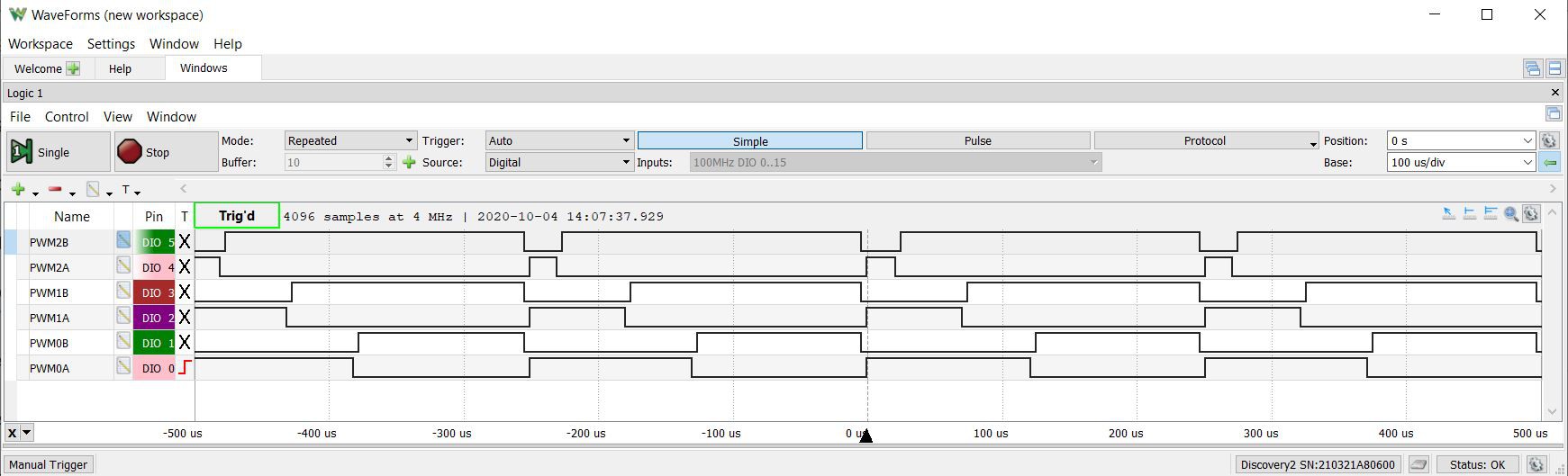
MCPWM with deadband
10/04/2020 at 06:23 • 0 commentsStill helping u/_jeem_
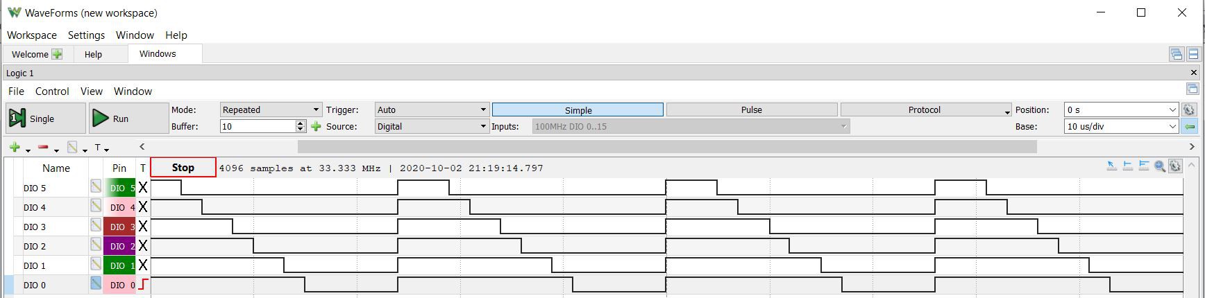
Syncronising the start pulses
Half bridge MOSFET control and avoiding shoot through
![]()
PWMxA is the highside FET
PWMxB is the lowside FET
High = FET on
#include "driver/mcpwm.h"
#include "soc/mcpwm_reg.h"
#include "soc/mcpwm_struct.h"
#include "wiring_private.h" // pinPeripheral() function

// MCPWM Pins
#define GPIO_PWM0A_OUT 15   //Set GPIO 15 as PWM0A
#define GPIO_PWM0B_OUT 02   //Set GPIO 02 as PWM0B
#define GPIO_PWM1A_OUT 0   //Set GPIO 00 as PWM1A
#define GPIO_PWM1B_OUT 04   //Set GPIO 04 as PWM1B
#define GPIO_PWM2A_OUT 16   //Set GPIO 16 as PWM2A
#define GPIO_PWM2B_OUT 17   //Set GPIO 17 as PWM2B

static void setup_mcpwm_pins()
{
    Serial.println("initializing mcpwm control gpio...n");
    mcpwm_gpio_init(MCPWM_UNIT_0, MCPWM0A, GPIO_PWM0A_OUT);
    mcpwm_gpio_init(MCPWM_UNIT_0, MCPWM0B, GPIO_PWM0B_OUT);
    mcpwm_gpio_init(MCPWM_UNIT_0, MCPWM1A, GPIO_PWM1A_OUT);
    mcpwm_gpio_init(MCPWM_UNIT_0, MCPWM1B, GPIO_PWM1B_OUT);
    mcpwm_gpio_init(MCPWM_UNIT_0, MCPWM2A, GPIO_PWM2A_OUT);
    mcpwm_gpio_init(MCPWM_UNIT_0, MCPWM2B, GPIO_PWM2B_OUT);
} // setup_pins()

static void setup_mcpwm()
{
   setup_mcpwm_pins();

   mcpwm_config_t pwm_config;
   pwm_config.frequency = 4000;  //frequency = 20000Hz
   pwm_config.cmpr_a = 50.0;      //duty cycle of PWMxA = 50.0%
   pwm_config.cmpr_b = 50.0;      //duty cycle of PWMxB = 50.0%
   pwm_config.counter_mode = MCPWM_UP_COUNTER; //MCPWM_UP_DOWN_COUNTER; // Up-down counter (triangle wave)
   pwm_config.duty_mode = MCPWM_DUTY_MODE_0; // Active HIGH
   mcpwm_init(MCPWM_UNIT_0, MCPWM_TIMER_0, &pwm_config);    //Configure PWM0A & PWM0B with above settings
   mcpwm_init(MCPWM_UNIT_0, MCPWM_TIMER_1, &pwm_config);    //Configure PWM0A & PWM0B with above settings
   mcpwm_init(MCPWM_UNIT_0, MCPWM_TIMER_2, &pwm_config);    //Configure PWM0A & PWM0B with above settings
   mcpwm_deadtime_enable(MCPWM_UNIT_0, MCPWM_TIMER_0, MCPWM_ACTIVE_HIGH_COMPLIMENT_MODE, 40, 40);
   mcpwm_deadtime_enable(MCPWM_UNIT_0, MCPWM_TIMER_1, MCPWM_ACTIVE_HIGH_COMPLIMENT_MODE, 40, 40);
   mcpwm_deadtime_enable(MCPWM_UNIT_0, MCPWM_TIMER_2, MCPWM_ACTIVE_HIGH_COMPLIMENT_MODE, 40, 40);

   mcpwm_sync_enable(MCPWM_UNIT_0, MCPWM_TIMER_0, MCPWM_SELECT_SYNC_INT0, 0);
   mcpwm_sync_enable(MCPWM_UNIT_0, MCPWM_TIMER_1, MCPWM_SELECT_SYNC_INT0, 0);
   mcpwm_sync_enable(MCPWM_UNIT_0, MCPWM_TIMER_2, MCPWM_SELECT_SYNC_INT0, 0);

   MCPWM0.timer[0].sync.out_sel = 1;
   delayMicroseconds(1000);
   MCPWM0.timer[0].sync.out_sel = 0;

   int pwm0 = 50;
   int pwm1 = 30;
   int pwm2 = 10;
   mcpwm_set_duty(MCPWM_UNIT_0, MCPWM_TIMER_0, MCPWM_OPR_A, pwm0);
   mcpwm_set_duty(MCPWM_UNIT_0, MCPWM_TIMER_0, MCPWM_OPR_B, pwm0);
   mcpwm_set_duty(MCPWM_UNIT_0, MCPWM_TIMER_1, MCPWM_OPR_A, pwm1);
   mcpwm_set_duty(MCPWM_UNIT_0, MCPWM_TIMER_1, MCPWM_OPR_B, pwm1);
   mcpwm_set_duty(MCPWM_UNIT_0, MCPWM_TIMER_2, MCPWM_OPR_A, pwm2);
   mcpwm_set_duty(MCPWM_UNIT_0, MCPWM_TIMER_2, MCPWM_OPR_B, pwm2);
} // setup_mcpwm

void setup() {
  setup_mcpwm();
}

void loop() {
}
This is not ideal as I still have to set the duty cycle for both PWMxA and PWMxB and this could be prone to errors.
I would like to use PWMxA only
I thought that
MCPWM_ACTIVE_RED_FED_FROM_PWMXA
or
MCPWM_ACTIVE_RED_FED_FROM_PWMXB
would work correctly but it does not.
-
Reddit Help u/_jeem_
10/02/2020 at 13:30 • 0 commentshttps://www.reddit.com/r/esp32/comments/j0lbrl/update_how_to_remove_delay_between_pwm_signals/
![]()
#include "driver/mcpwm.h" #include "soc/mcpwm_reg.h" #include "soc/mcpwm_struct.h" #include "wiring_private.h" // pinPeripheral() function // MCPWM Pins #define GPIO_PWM0A_OUT 15 //Set GPIO 15 as PWM0A #define GPIO_PWM0B_OUT 02 //Set GPIO 02 as PWM0B #define GPIO_PWM1A_OUT 0 //Set GPIO 00 as PWM1A #define GPIO_PWM1B_OUT 04 //Set GPIO 04 as PWM1B #define GPIO_PWM2A_OUT 16 //Set GPIO 16 as PWM2A #define GPIO_PWM2B_OUT 17 //Set GPIO 17 as PWM2B static void setup_mcpwm_pins() { Serial.println("initializing mcpwm control gpio...n"); mcpwm_gpio_init(MCPWM_UNIT_0, MCPWM0A, GPIO_PWM0A_OUT); mcpwm_gpio_init(MCPWM_UNIT_0, MCPWM0B, GPIO_PWM0B_OUT); mcpwm_gpio_init(MCPWM_UNIT_0, MCPWM1A, GPIO_PWM1A_OUT); mcpwm_gpio_init(MCPWM_UNIT_0, MCPWM1B, GPIO_PWM1B_OUT); mcpwm_gpio_init(MCPWM_UNIT_0, MCPWM2A, GPIO_PWM2A_OUT); mcpwm_gpio_init(MCPWM_UNIT_0, MCPWM2B, GPIO_PWM2B_OUT); } // setup_pins() static void setup_mcpwm() { setup_mcpwm_pins(); mcpwm_config_t pwm_config; pwm_config.frequency = 40000; //frequency = 20000Hz pwm_config.cmpr_a = 50.0; //duty cycle of PWMxA = 50.0% pwm_config.cmpr_b = 50.0; //duty cycle of PWMxB = 50.0% pwm_config.counter_mode = MCPWM_UP_COUNTER; //MCPWM_UP_DOWN_COUNTER; // Up-down counter (triangle wave) pwm_config.duty_mode = MCPWM_DUTY_MODE_0; // Active HIGH mcpwm_init(MCPWM_UNIT_0, MCPWM_TIMER_0, &pwm_config); //Configure PWM0A & PWM0B with above settings mcpwm_init(MCPWM_UNIT_0, MCPWM_TIMER_1, &pwm_config); //Configure PWM0A & PWM0B with above settings mcpwm_init(MCPWM_UNIT_0, MCPWM_TIMER_2, &pwm_config); //Configure PWM0A & PWM0B with above settings mcpwm_sync_enable(MCPWM_UNIT_0, MCPWM_TIMER_0, MCPWM_SELECT_SYNC_INT0, 0); mcpwm_sync_enable(MCPWM_UNIT_0, MCPWM_TIMER_1, MCPWM_SELECT_SYNC_INT0, 0); mcpwm_sync_enable(MCPWM_UNIT_0, MCPWM_TIMER_2, MCPWM_SELECT_SYNC_INT0, 0); MCPWM0.timer[0].sync.out_sel = 1; delayMicroseconds(100); MCPWM0.timer[0].sync.out_sel = 0; mcpwm_set_duty(MCPWM_UNIT_0, MCPWM_TIMER_0, MCPWM_OPR_A, 70); mcpwm_set_duty(MCPWM_UNIT_0, MCPWM_TIMER_0, MCPWM_OPR_B, 60); mcpwm_set_duty(MCPWM_UNIT_0, MCPWM_TIMER_1, MCPWM_OPR_A, 50); mcpwm_set_duty(MCPWM_UNIT_0, MCPWM_TIMER_1, MCPWM_OPR_B, 40); mcpwm_set_duty(MCPWM_UNIT_0, MCPWM_TIMER_2, MCPWM_OPR_A, 30); mcpwm_set_duty(MCPWM_UNIT_0, MCPWM_TIMER_2, MCPWM_OPR_B, 20); } // setup_mcpwm void setup() { setup_mcpwm(); } void loop() { } -
Joint Control - Cycloidal Brushless Actuator
09/04/2020 at 15:19 • 0 comments -
Haptic Control using ESP-Now
08/16/2020 at 16:51 • 0 comments -
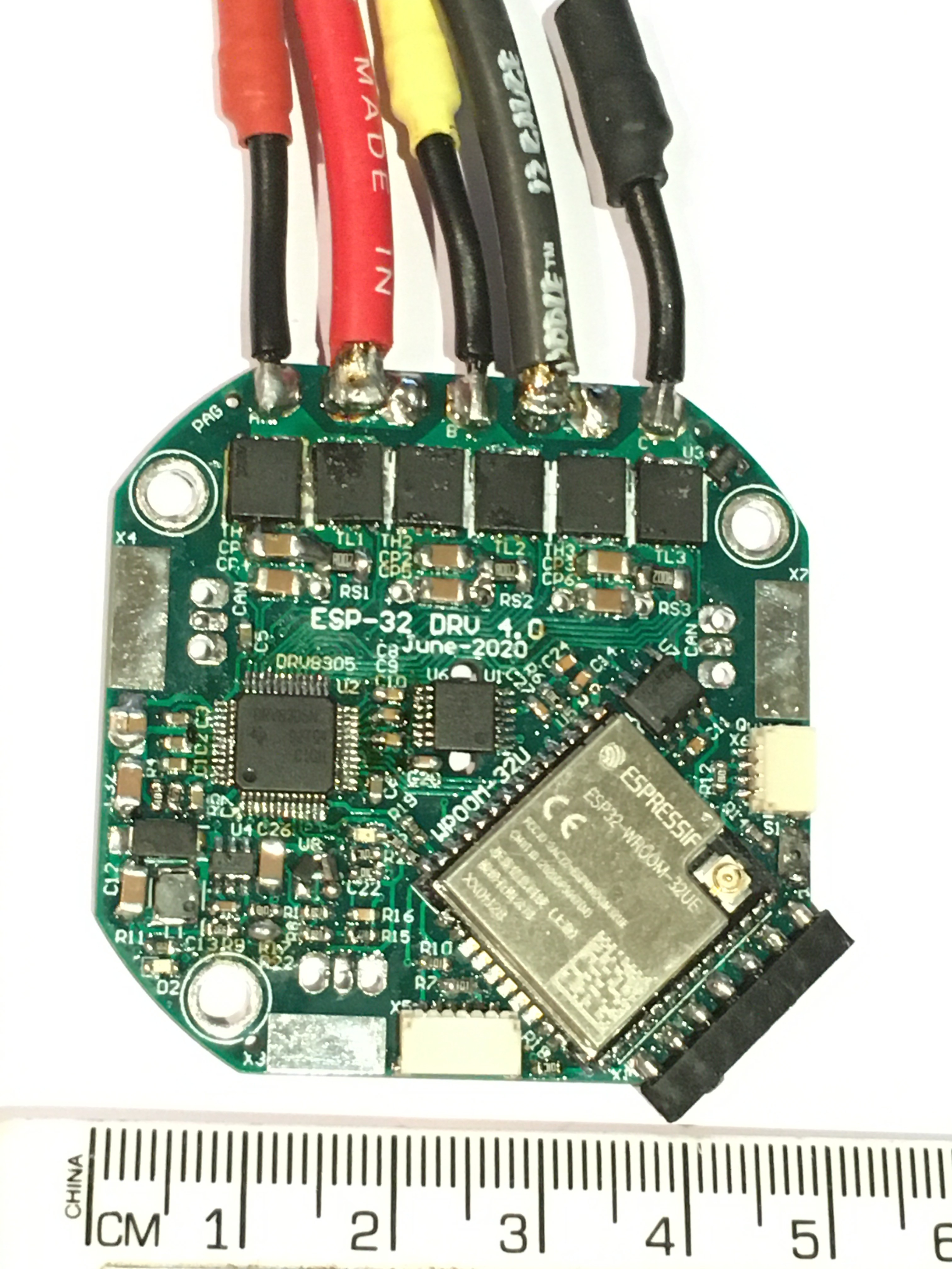
Prototype is controlling a BLDC motor
07/29/2020 at 16:18 • 0 commentsBoards can in from JLC PCB, components can in from LCSC and Mouser.
Hand populated the first one, testing as I went. I have a stencil for the next few.
![]()
A few little mistakes.
- Auto Power switch over between USB 5V and Battery Voltage had a high forward voltage and had to be replaced.
- Needed a pull down on ESP-32 IO12
- Had to Parallel Caps for the Charge Pump because I ordered the wrong one.
![]()
Programs via Arduino IDE using USB-TTL-3V3
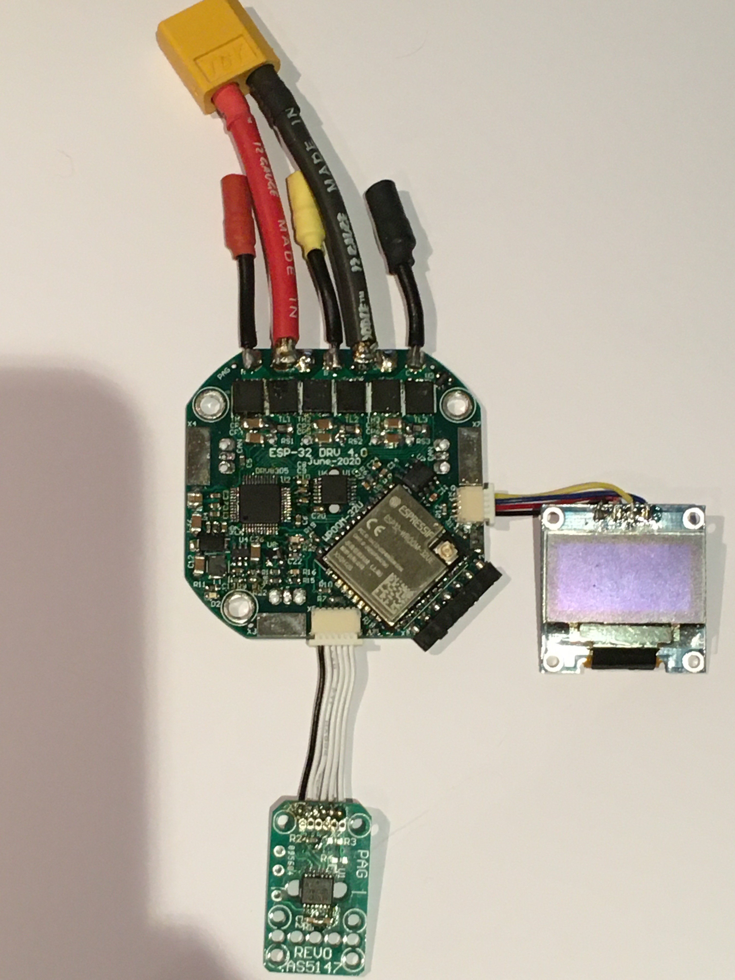
I can control a motor and a joint's position via bluetooth and display into on the I2C OLED (FET Temp, Battery Voltage, Joint Position, Motor current).
Has two absolute magnetic encoders, for for motor position and one for joint position
I do not recommend Bluetooth/wifi for joint control.
CAN is also up and running.
-
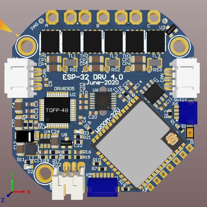
10 boards on order at JLC
06/14/2020 at 16:30 • 0 comments![]()
Connectors clockwise from the top
- BLDC motor connectors & Power In/Out
- CAN in/out
- qwiic
- ESP-32 Prog
- Encoder SPI
- Fan or Servo CTRL
- CAN out/in
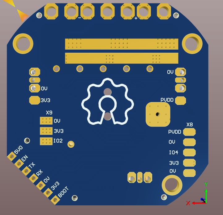
![]()
Connectors on the back
- FAN or Servo
- ESP-32 Prog
- Pot
-
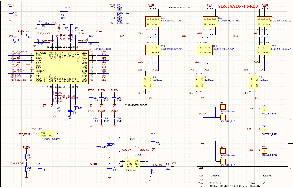
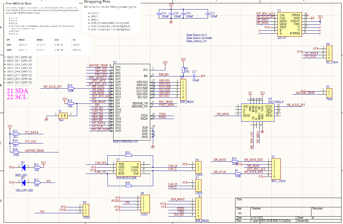
ESP-32 and DRV8305N Schematic
03/31/2020 at 08:00 • 0 commentsPDF in files
ESP-32 BLDC Robot Actuator Controller
ESP-32 WROOM-32D has Three phase Centre Aligned MC-PWM, Dual SPI, I2C, 2MHz ADC, UART and CAN. Enough for a controller.