Paul Gould
-
SPI in an IRQ
02/27/2020 at 16:39 • 0 commentsThe standard SPI Transfer code does tot work well in an IRQ mainly becaise it is run out of FLASH. Uese the IRAM_ATTR to put it in RAM.
Other digitalWrte() is slow and should not be uses in the IRQ.
Use GPIO.out_w1ts = ((uint32_t)1 << IO_PIN_Number); to set the pin high
Use GPIO.out_w1ts = ((uint32_t)1 << IO_PIN_Number); to set the pin low
This can only be used when the IO_PIN_Number is 0-31
There is other code for 32-39 pins.
SPI Set-up
#include "driver/periph_ctrl.h"
#include "driver/spi_master.h"
#include "soc/gpio_sig_map.h"
#include "soc/spi_reg.h"
#include "soc/dport_reg.h"
#include "soc/spi_struct.h"static const int spiClk = 4000000; // 1 MHz
SPIClass * hspi = NULL;void IRAM_ATTR SPIInit(void) { hspi = new SPIClass(HSPI); hspi->begin(); pinMode(INT_ENC_nCS, OUTPUT); pinMode(EXT_ENC_nCS, OUTPUT); pinMode(DRV_nSCS, OUTPUT); GPIO.out_w1ts = ((uint32_t)1 << INT_ENC_nCS); GPIO.out_w1ts = ((uint32_t)1 << EXT_ENC_nCS); GPIO.out_w1ts = ((uint32_t)1 << DRV_nSCS); hspi->beginTransaction(SPISettings(spiClk, MSBFIRST, SPI_MODE1)); SPI2.mosi_dlen.usr_mosi_dbitlen = (1 * 16) - 1; SPI2.miso_dlen.usr_miso_dbitlen = (1 * 16) - 1; }
void IRAM_ATTR SPI_Read_Encoder(){ GPIO.out_w1tc = ((uint32_t)1 << INT_ENC_nCS); SPI2.data_buf[0] = 0xFFFF; SPI2.cmd.usr = 1; while(SPI2.cmd.usr); GPIO.out_w1ts = ((uint32_t)1 << INT_ENC_nCS); encoder_int = SPI2.data_buf[0] & 0xFFFF; if(!SPI2.ctrl.rd_bit_order){ encoder_int = (encoder_int >> 8) | (encoder_int << 8); } encoder_int = encoder_int & 0x3FFF ; } -
Hi Resolution Centre Aligned Three Phase MCPWM
02/27/2020 at 16:25 • 0 commentsThe standard Libraries for Arduino by Espressif are very limiting. Previously I had to fix the Sync Function. Now the problem is Frequency, resolution and updating the duty cycle in an interrupt. There is an argument to make on getting the interrupt sub-routine very short. All of my motor commutation code (and SPI reads) are within an 5KHz timer. It consumes 5-10% CPU time. By default the Arduino code runs out of FLASH and running FLASH code in an interrupt causes problems (more info on why is needed).
MCPWM Initialization code
#define TIMER_CLK_PRESCALE 1
#define MCPWM_CLK_PRESCALE 0
#define MCPWM_PERIOD_PRESCALE 4
#define MCPWM_PERIOD_PERIOD 2048
static void IRAM_ATTR setup_mcpwm()
{
     setup_mcpwm_pins();

     mcpwm_config_t pwm_config;
     pwm_config.frequency = 4000000;  //frequency = 20000Hz
     pwm_config.cmpr_a = 0;      //duty cycle of PWMxA = 50.0%
     pwm_config.cmpr_b = 0;      //duty cycle of PWMxB = 50.0%
     pwm_config.counter_mode = MCPWM_UP_DOWN_COUNTER; // Up-down counter (triangle wave)
     pwm_config.duty_mode = MCPWM_DUTY_MODE_0; // Active HIGH
     mcpwm_init(MCPWM_UNIT_0, MCPWM_TIMER_0, &pwm_config);    //Configure PWM0A & PWM0B with above settings
     mcpwm_init(MCPWM_UNIT_0, MCPWM_TIMER_1, &pwm_config);    //Configure PWM0A & PWM0B with above settings
     mcpwm_init(MCPWM_UNIT_0, MCPWM_TIMER_2, &pwm_config);    //Configure PWM0A & PWM0B with above settings
     Serial.print("clk_cfg.prescale = ");
     Serial.println( MCPWM0.clk_cfg.prescale);
     Serial.print("timer[0].period.prescale = ");
     Serial.println( MCPWM0.timer[0].period.prescale);
     Serial.print("timer[0].period.period = ");
     Serial.println( MCPWM0.timer[0].period.period);
     Serial.print("timer[0].period.upmethod = ");
     Serial.println( MCPWM0.timer[0].period.upmethod);

     mcpwm_stop(MCPWM_UNIT_0, MCPWM_TIMER_0);
     mcpwm_stop(MCPWM_UNIT_0, MCPWM_TIMER_1);
     mcpwm_stop(MCPWM_UNIT_0, MCPWM_TIMER_2);
     MCPWM0.clk_cfg.prescale = MCPWM_CLK_PRESCALE;

     MCPWM0.timer[0].period.prescale = MCPWM_PERIOD_PRESCALE;
     MCPWM0.timer[1].period.prescale = MCPWM_PERIOD_PRESCALE;
     MCPWM0.timer[2].period.prescale = MCPWM_PERIOD_PRESCALE;
     delay(1);
     MCPWM0.timer[0].period.period = MCPWM_PERIOD_PERIOD;
     MCPWM0.timer[1].period.period = MCPWM_PERIOD_PERIOD;
     MCPWM0.timer[2].period.period = MCPWM_PERIOD_PERIOD;
     delay(1);
     MCPWM0.timer[0].period.upmethod =0;
     MCPWM0.timer[1].period.upmethod =0;
     MCPWM0.timer[2].period.upmethod =0;
     delay(1);
     Serial.print("clk_cfg.prescale = ");
     Serial.println( MCPWM0.clk_cfg.prescale);
     Serial.print("timer[0].period.prescale = ");
     Serial.println( MCPWM0.timer[0].period.prescale);
     Serial.print("timer[0].period.period = ");
     Serial.println( MCPWM0.timer[0].period.period);
     mcpwm_start(MCPWM_UNIT_0, MCPWM_TIMER_0);
     mcpwm_start(MCPWM_UNIT_0, MCPWM_TIMER_1);
     mcpwm_start(MCPWM_UNIT_0, MCPWM_TIMER_2);

     mcpwm_sync_enable(MCPWM_UNIT_0, MCPWM_TIMER_0, MCPWM_SELECT_SYNC_INT0, 0);
     mcpwm_sync_enable(MCPWM_UNIT_0, MCPWM_TIMER_1, MCPWM_SELECT_SYNC_INT0, 0);
     mcpwm_sync_enable(MCPWM_UNIT_0, MCPWM_TIMER_2, MCPWM_SELECT_SYNC_INT0, 0);
     delayMicroseconds(1000);
     MCPWM0.timer[0].sync.out_sel = 1;
     delayMicroseconds(1000);
     MCPWM0.timer[0].sync.out_sel = 0;

} // setup_mcpwm
Some rules
STOP MCPWM before period, etc update
START MCPWM before SYNC
Delay long enough for at least one period before disabling sync .
Use IRAM_ATTR to change the code from FLASH based to RAM based for putting into the Interrupt
void IRAM_ATTR Three_Phases(void)
{
  if (Motor_on==0)
  {
      PWMUU = 0;
      PWMVV = 0;
      PWMWW = 0;
  }
  MCPWM0.channel[0].cmpr_value[MCPWM_OPR_A].cmpr_val = PWMUU;
  MCPWM0.channel[1].cmpr_value[MCPWM_OPR_A].cmpr_val = PWMVV;
  MCPWM0.channel[2].cmpr_value[MCPWM_OPR_A].cmpr_val = PWMWW;
}
Because MCPWM0.timer[2].period.upmethod =0; is instant update this code update Duty cycle right away.
May have to check for glitches or change upmethod to start of period. -
Motor is running and controllable over Bluetooth
02/27/2020 at 15:58 • 1 commentWROOM-32D Development kit
3x BTS7980 Half Bridge FETs
AS5147 Absolute Magnetic Encoder
OLED Display SSD1306
CAN Transceiver
QX-Motor QX4208
3D printed Cycloidal Gearbox from this project
Connect via Bluetooth on TeraTerm
-
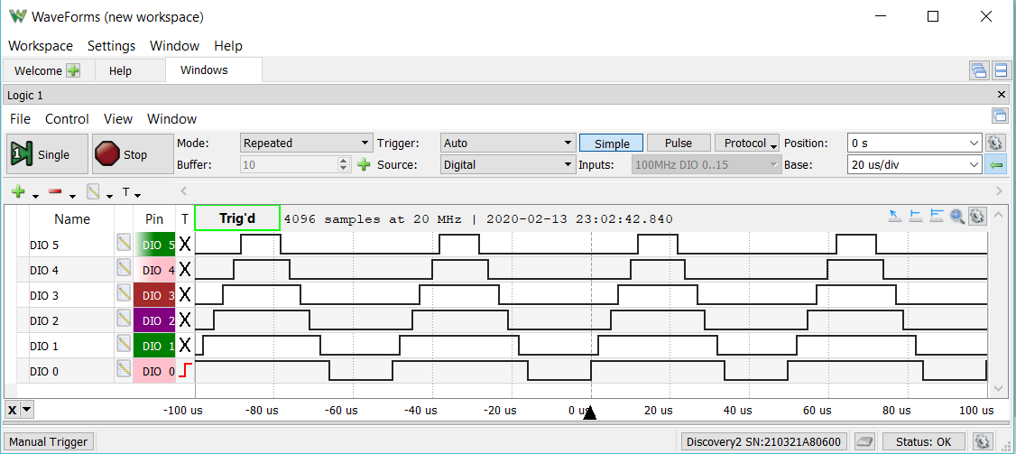
Three Phase Centre Aligned MC PWM
02/13/2020 at 15:25 • 0 commentsStarting point for Brushless motor control is the get the required features up and running. The ESP-32 has a MCPWM (Motor Control) hardware block. The hardest part was getting the "centre aligned" working with the many different types of sync function. The one I needed was missing from the header file.
mcpwm.h for the ESP32 is missing some enums
edit
MCPWM_SELECT_SYNC_OFF, /*!< SYNC is off*/
was missing a comma
/**
 * @brief MCPWM select sync signal input
 */
typedef enum {
    MCPWM_SELECT_SYNC_OFF,          /*!< SYNC is off*/
    MCPWM_SELECT_SYNC_INT0,        /*!<Select SYNC0 as internal*/
    MCPWM_SELECT_SYNC_INT1,        /*!<Select SYNC1 as internal*/
    MCPWM_SELECT_SYNC_INT2,        /*!<Select SYNC2 as internal*/
    MCPWM_SELECT_SYNC0,            /*!<Select SYNC0 as input*/
    MCPWM_SELECT_SYNC1,            /*!<Select SYNC1 as input*/
    MCPWM_SELECT_SYNC2,            /*!<Select SYNC2 as input*/
} mcpwm_sync_signal_t;
The online file is located at
I have issued a bug fix request.
Arduino ino file
#include "driver/mcpwm.h"
#include "soc/mcpwm_reg.h"
#include "soc/mcpwm_struct.h"

// MCPWM Pins
#define GPIO_PWM0A_OUT 15   //Set GPIO 15 as PWM0A
#define GPIO_PWM0B_OUT 02   //Set GPIO 02 as PWM0B
#define GPIO_PWM1A_OUT 00   //Set GPIO 00 as PWM1A
#define GPIO_PWM1B_OUT 04   //Set GPIO 04 as PWM1B
#define GPIO_PWM2A_OUT 16   //Set GPIO 16 as PWM2A
#define GPIO_PWM2B_OUT 17   //Set GPIO 17 as PWM2B

static void setup_mcpwm_pins()
{
    Serial.println("initializing mcpwm control gpio...n");
    mcpwm_gpio_init(MCPWM_UNIT_0, MCPWM0A, GPIO_PWM0A_OUT);
    mcpwm_gpio_init(MCPWM_UNIT_0, MCPWM0B, GPIO_PWM0B_OUT);
    mcpwm_gpio_init(MCPWM_UNIT_0, MCPWM1A, GPIO_PWM1A_OUT);
    mcpwm_gpio_init(MCPWM_UNIT_0, MCPWM1B, GPIO_PWM1B_OUT);
    mcpwm_gpio_init(MCPWM_UNIT_0, MCPWM2A, GPIO_PWM2A_OUT);
    mcpwm_gpio_init(MCPWM_UNIT_0, MCPWM2B, GPIO_PWM2B_OUT);
} // setup_pins()

static void setup_mcpwm()
{
   setup_mcpwm_pins();

   mcpwm_config_t pwm_config;
   pwm_config.frequency = 40000;  //frequency = 20000Hz
   pwm_config.cmpr_a = 50.0;      //duty cycle of PWMxA = 50.0%
   pwm_config.cmpr_b = 50.0;      //duty cycle of PWMxB = 50.0%
   pwm_config.counter_mode = MCPWM_UP_DOWN_COUNTER; // Up-down counter (triangle wave)
   pwm_config.duty_mode = MCPWM_DUTY_MODE_0; // Active HIGH
   mcpwm_init(MCPWM_UNIT_0, MCPWM_TIMER_0, &pwm_config);    //Configure PWM0A & PWM0B with above settings
   mcpwm_init(MCPWM_UNIT_0, MCPWM_TIMER_1, &pwm_config);    //Configure PWM0A & PWM0B with above settings
   mcpwm_init(MCPWM_UNIT_0, MCPWM_TIMER_2, &pwm_config);    //Configure PWM0A & PWM0B with above settings

   mcpwm_sync_enable(MCPWM_UNIT_0, MCPWM_TIMER_0, MCPWM_SELECT_SYNC_OUT0, 0);
   mcpwm_sync_enable(MCPWM_UNIT_0, MCPWM_TIMER_1, MCPWM_SELECT_SYNC_OUT0, 0);
   mcpwm_sync_enable(MCPWM_UNIT_0, MCPWM_TIMER_2, MCPWM_SELECT_SYNC_OUT0, 0);

   MCPWM0.timer[0].sync.out_sel = 1;
   delayMicroseconds(100);
   MCPWM0.timer[0].sync.out_sel = 0;

   mcpwm_set_duty(MCPWM_UNIT_0, MCPWM_TIMER_0, MCPWM_OPR_A, 70);
   mcpwm_set_duty(MCPWM_UNIT_0, MCPWM_TIMER_0, MCPWM_OPR_B, 60);
   mcpwm_set_duty(MCPWM_UNIT_0, MCPWM_TIMER_1, MCPWM_OPR_A, 50);
   mcpwm_set_duty(MCPWM_UNIT_0, MCPWM_TIMER_1, MCPWM_OPR_B, 40);
   mcpwm_set_duty(MCPWM_UNIT_0, MCPWM_TIMER_2, MCPWM_OPR_A, 30);
   mcpwm_set_duty(MCPWM_UNIT_0, MCPWM_TIMER_2, MCPWM_OPR_B, 20);
} // setup_mcpwm

void setup()
{
   Serial.begin(115200);
   Serial.println( "Start ");
   setup_mcpwm();
} // setup()

void loop()
{
   Serial.println("D");
   delay(500);
} // loop()
I will have to look at dead-time next, so I only have to set three PWM values instead of six.
I could also save some pins and use the DRV8305 internal dead time feature.
-
Project Notes
02/11/2020 at 17:11 • 0 commentsInformation
Schematic Guidelines
https://randomnerdtutorials.com/esp32-pinout-reference-gpios/
https://learn.adafruit.com/assets/74367
https://learn.adafruit.com/huzzah32-esp32-breakout-board/pinouts
https://randomnerdtutorials.com/esp32-adc-analog-read-arduino-ide/
https://www.instructables.com/id/IOT-Made-Simple-Playing-With-the-ESP32-on-Arduino-/
https://docs.espressif.com/projects/esp-idf/en/latest/api-reference/peripherals/rmt.html
ESP-32 BLDC Robot Actuator Controller
ESP-32 WROOM-32D has Three phase Centre Aligned MC-PWM, Dual SPI, I2C, 2MHz ADC, UART and CAN. Enough for a controller.