 Tim
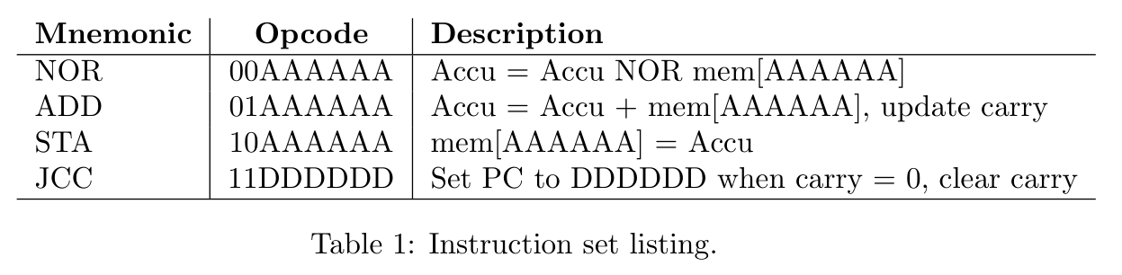
TimMany years ago I completed the challenge to fit a CPU into the smallest available CPLD on the market - the MCPU. Ever since then I have been pondering about a new challenge in minimalism in CPU-Design. I had completed a TTL-based CPU even before the MCPU. Clearly, the only direction left is to go fully discrete and build a minimal CPU out of discrete transistors.
To make things interesting and add a modern twist, I decided to investigate a logic family that uses light emitting diodes (LEDs) as an active element. LTL is a logic family from a past that never happened. It combines 1950s transistor logic with low current green InGaN LEDs that were invented in the 1990s.
I already completed the design up to a prototype of a sub-system (see header image) and will use this project to document the steps I have taken to get there.
Start with the first log by using this link or use this link to view all project logs on one page.
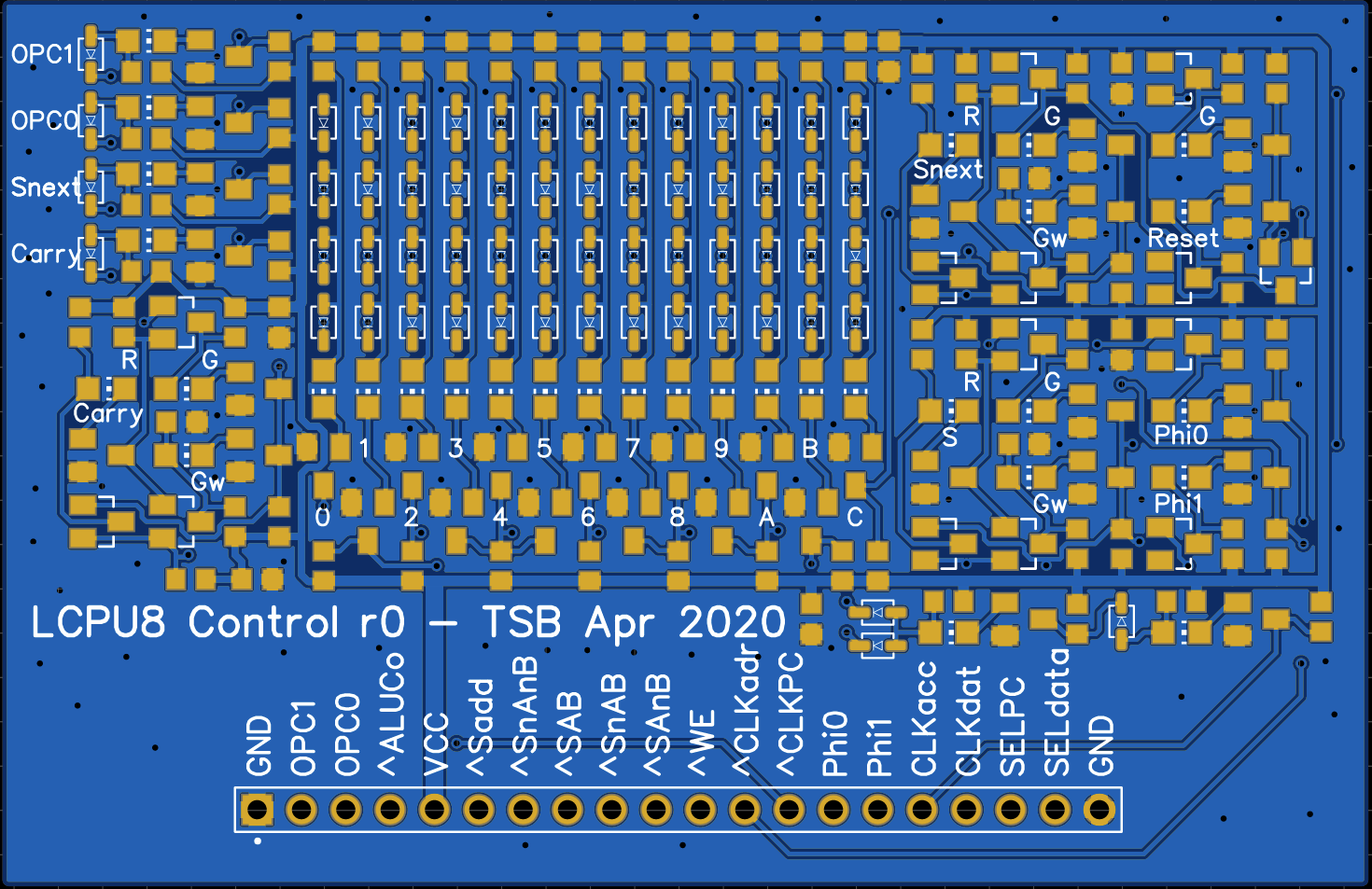
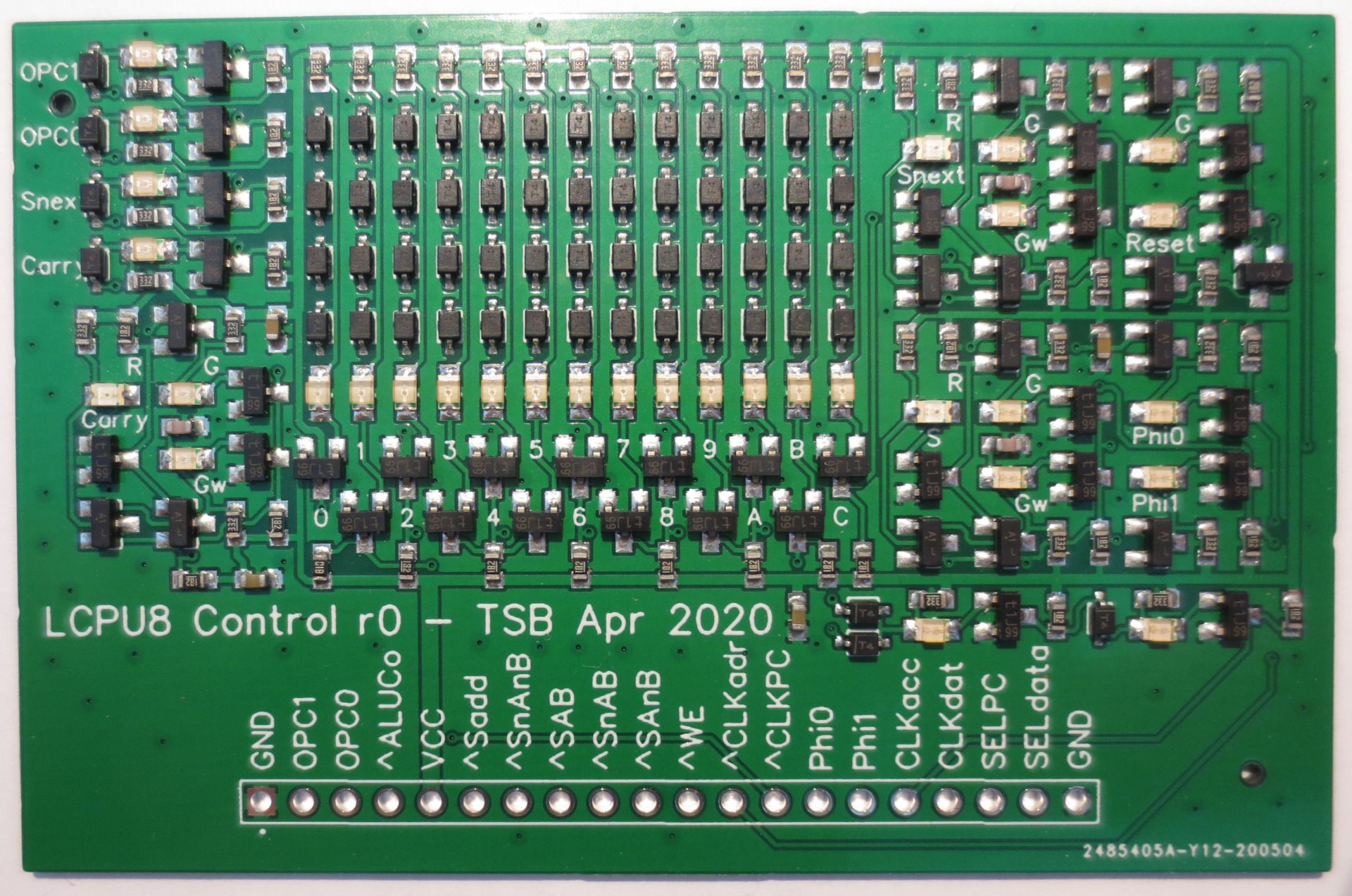 You can see a photograph of the PCB above. Unfortunately I already noticed a stupid mistake at this level: I forgot to route the reset signal to the I/O header. Since this was a circuit level mistake, no DRC caught this. Well, luckily that's easily fixed with an additional wire directly to the reset-driver.
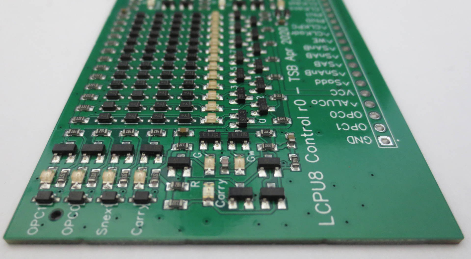 Due to the construction of the logic array, there is a LED for every row (input) and column (minterm/output), creating a very nice regular structure. Every mintern has an output inverter and uses wired-AND as a combiner. See previous log on control unit design.
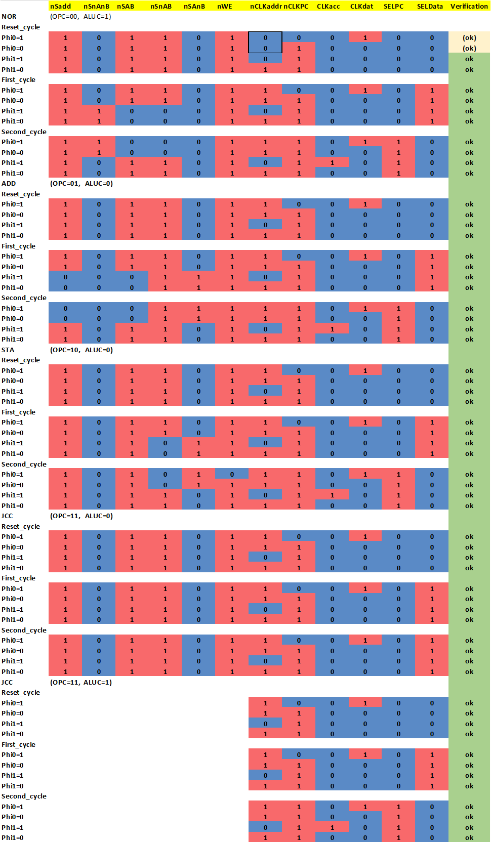
 You can see the control unit in action above. Due to it's irregular pattern, this truely seems to be "peak blinkenlight".
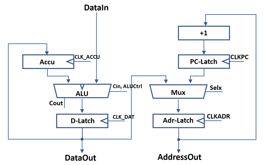
 Many of the simpler control signal encodings could be directly mapped to single gates. In additional you can find three latches for Carry signal and state enconding here, in what could best be described as "sea of gates". Very tedious to layout on the PCB, but straightforward in implementation by using the building blocks I designed earlier.
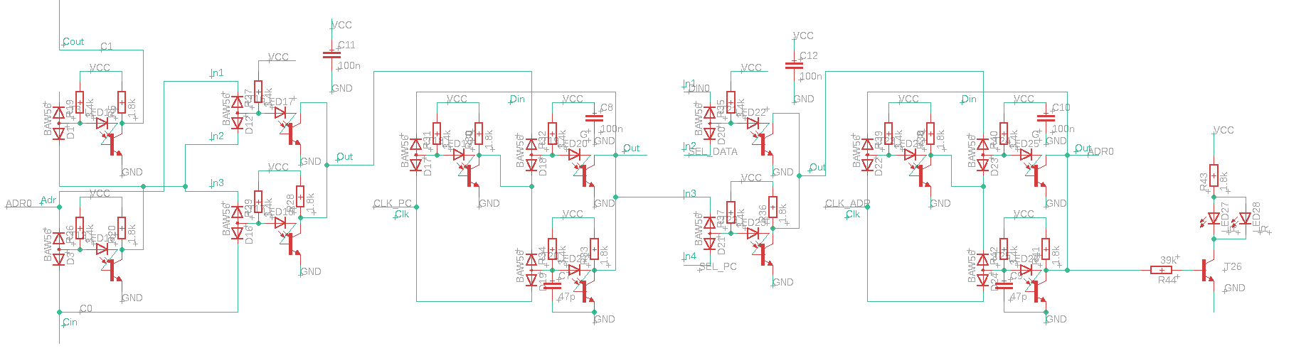
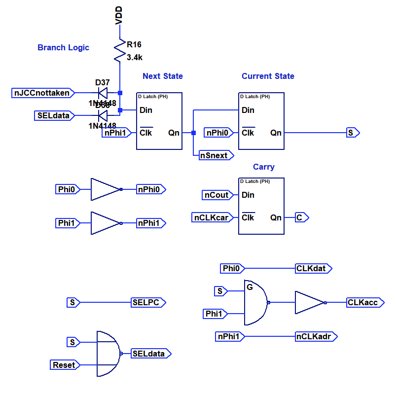 Of much more interest is the AND-OR-INVERT logic array that is used to decode the more complex signals, specifically the opcode into ALU control signals. You can see the circuit below.
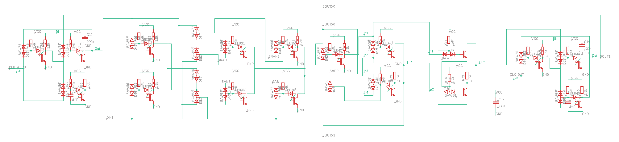
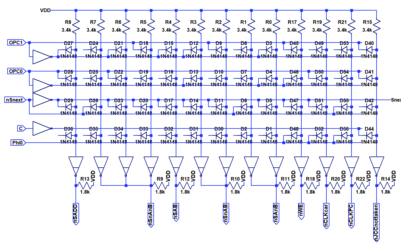 Instead of using double diodes I switched to single diodes to allow layout in a regular matrix. Input signals are routed vertically on the rear side, output terms vertically on the front side. Typically both the inverted and non-inverted inputs signals are provided by means of the inverters on the left side. Each column represents a multiple input AND-gate (Minterm). By connecting the diodes not at all or to the positive or negative input signal it is possible to crate any convolution of AND-operation. The opon collecter inverters at the bottom perform a "NOR" operation on any number of input terms. By combining these, it is possible to implement any boolean operation with only minimal changes in the layout. I decided to populate also unused diodes in the matrix to allow for later fixability.
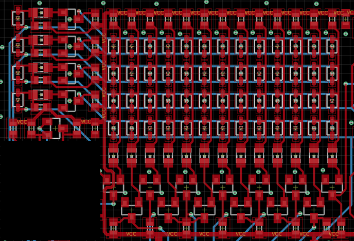
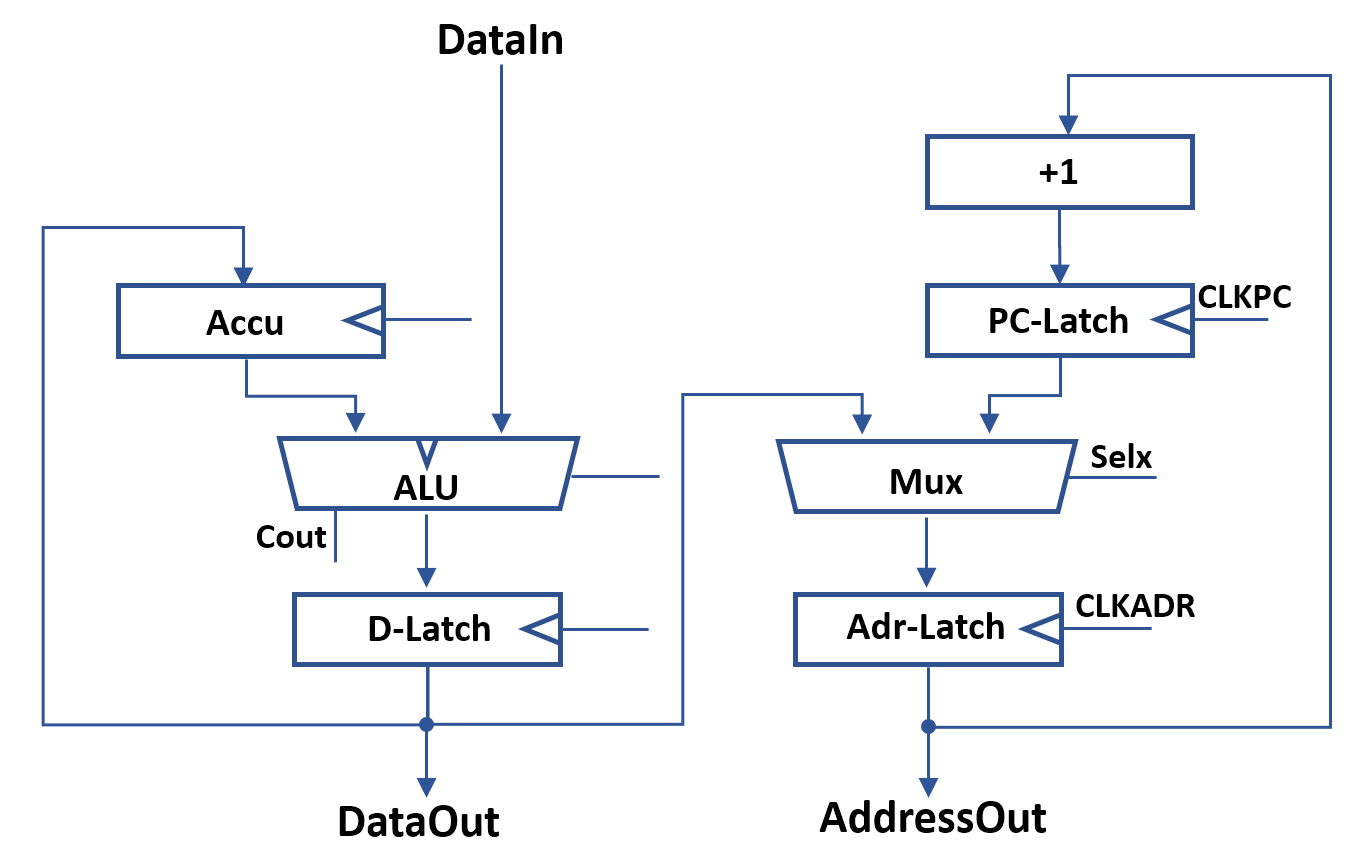
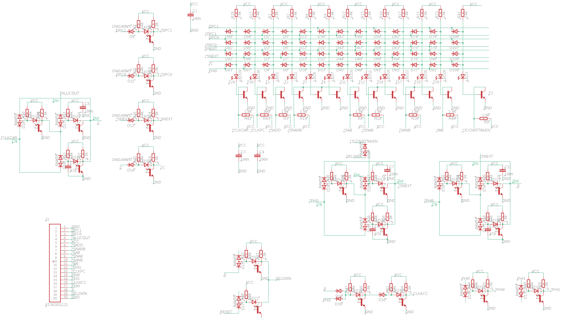 For the sake of completness, the full schematics for the board level implementation are shown above.
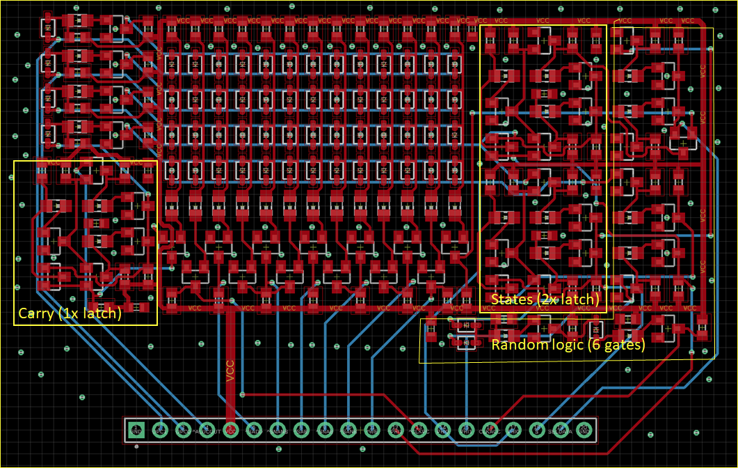
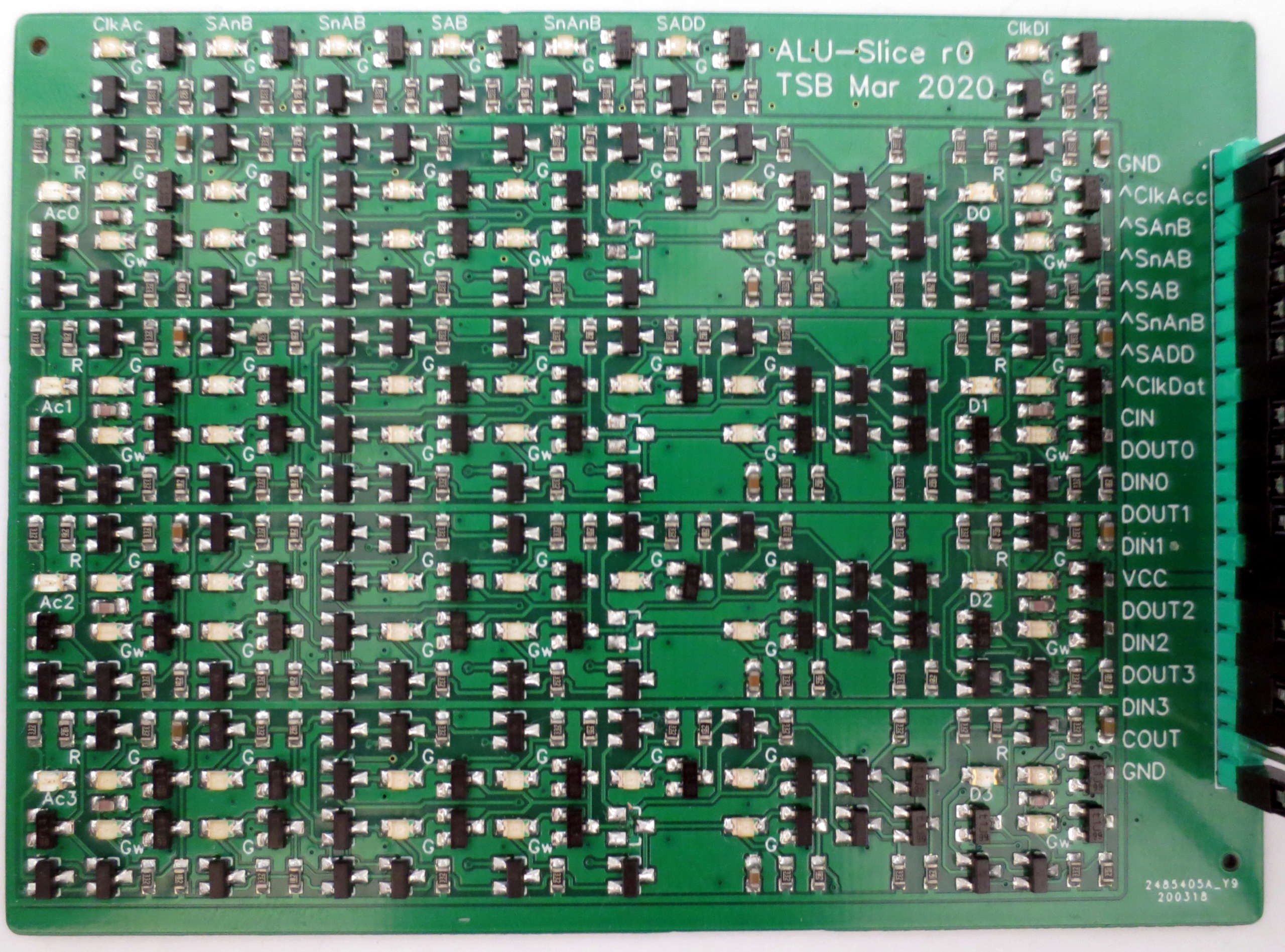 The dual-input diodes for the boolean unit multiplexer line up neatly in one row.
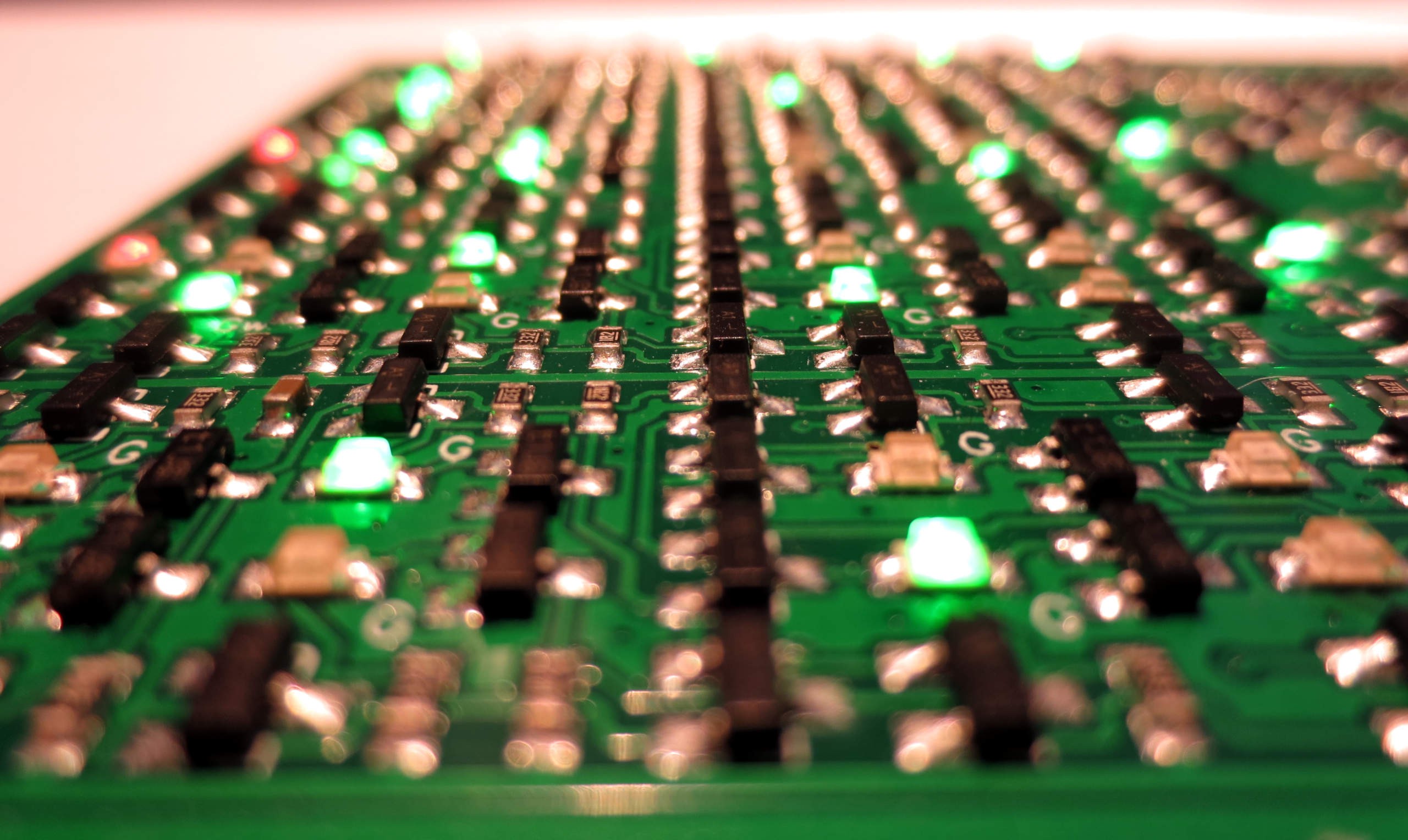 I tested the board using an ATMega168 to generate stimulus signals. Unfortunately, I found a small mistake I made earlier in the design: The generate term in the carry chain should not have an additional carry input, see below. Luckily it was easily possible to fix this by removing one diode per slice from the board. You can see the unpopulated pads in the center of the top down image.
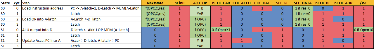
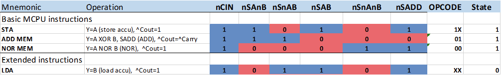
 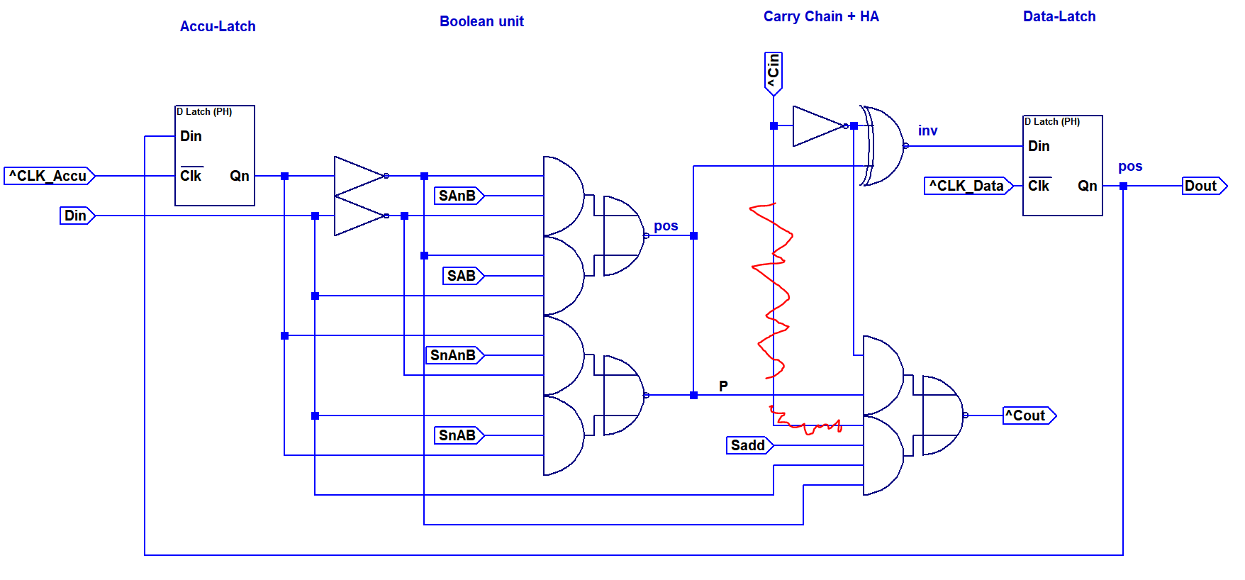 The list below shows the control signal configurations that were tested. Only the first three cases apply to operations that are used by the MCPU ISA. In addition, Y=B is needed for address loading.
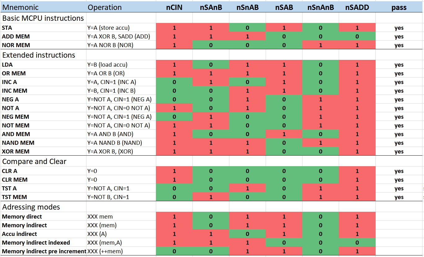 Finally, the ALU board in action, repeating a sequence of ADD A,3 and NEG A:
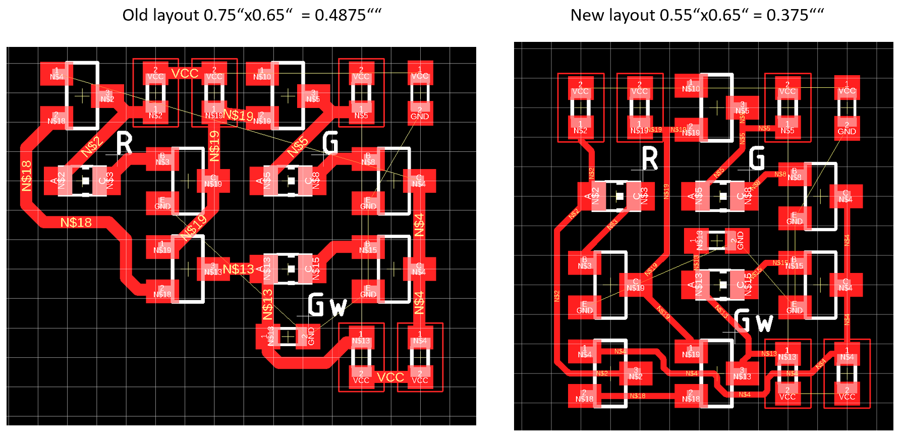 The image above shows a comparison of the old and new polarity hold latch layout. The new layout is much more dense and takes 30% less PCB space. One interesting observation was that going from 0603 to 0402 resistors did increase the layout area, since it was not possible to pass connections below the components anymore. Therfore I stayed with 0603 passives. Using smaller transistor packages was not an option either, since I was not able to source the transitor in a smaller package.
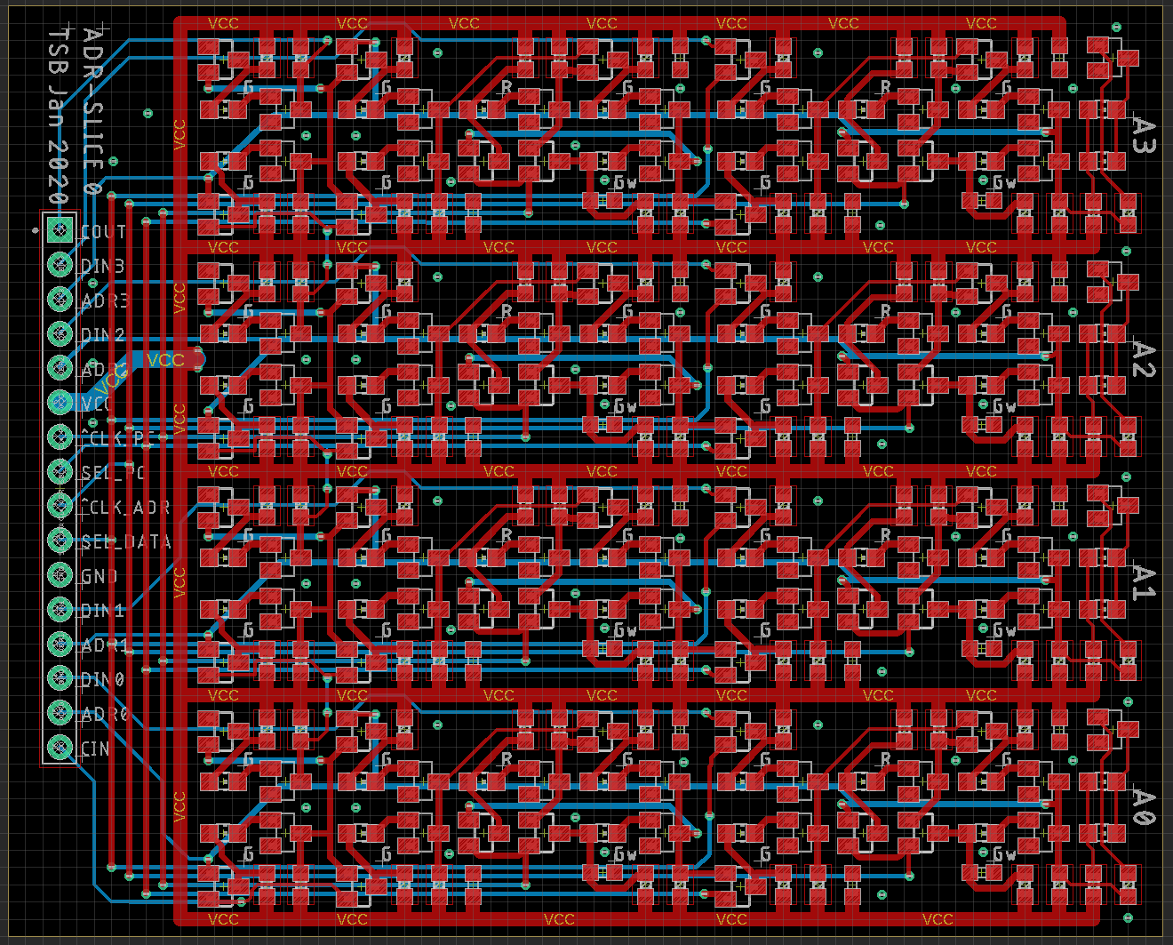
 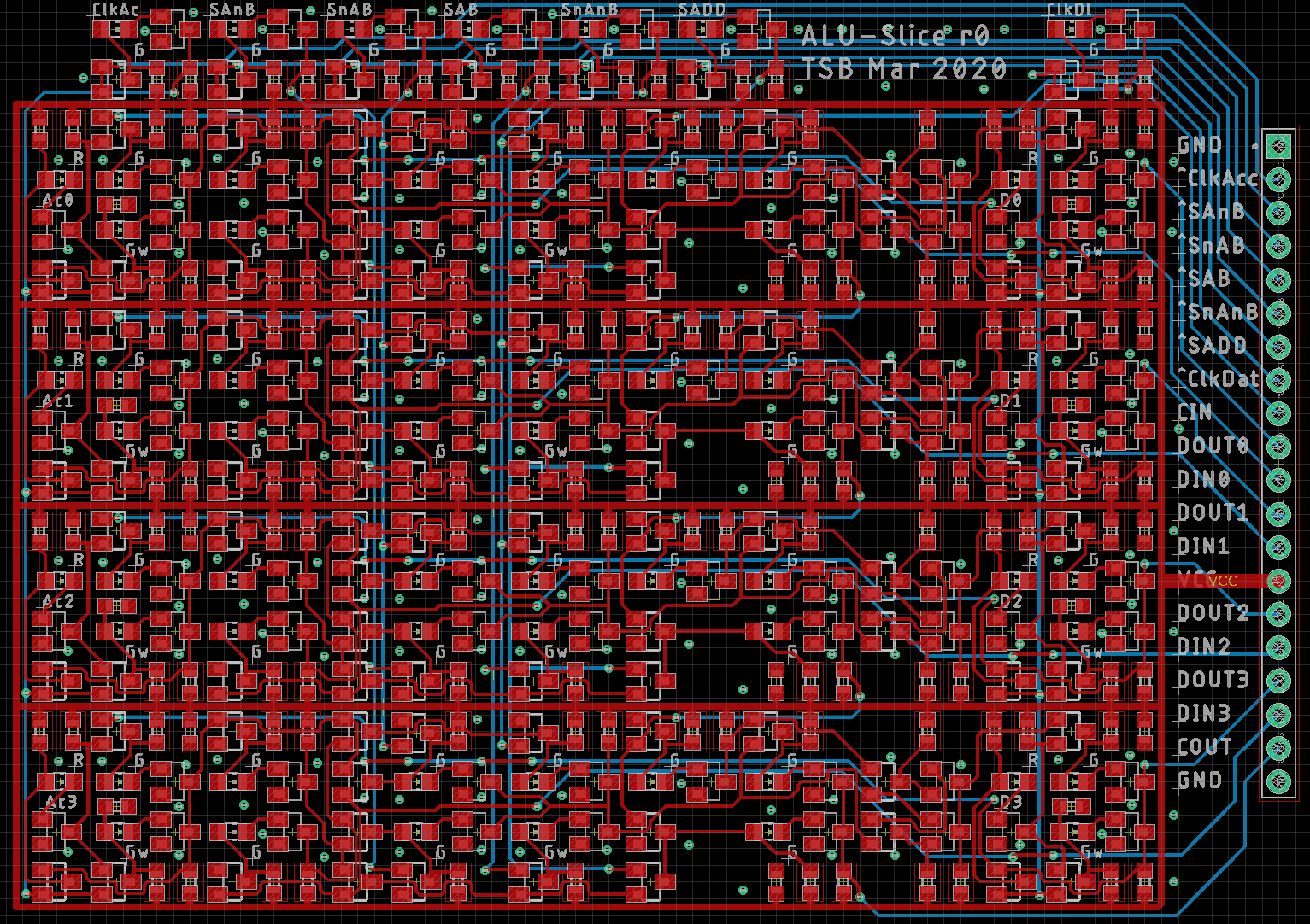 The full layout, excluding ground plane, is shown above. Again, it was possible to fit four bit-slices on one board. In contrast to the previous design, I decided to include buffers for the control signals, located at the top. The fan out of the clock signal on this board is 8 gates. Combining several boards requires a clock tree for proper drive-ability.
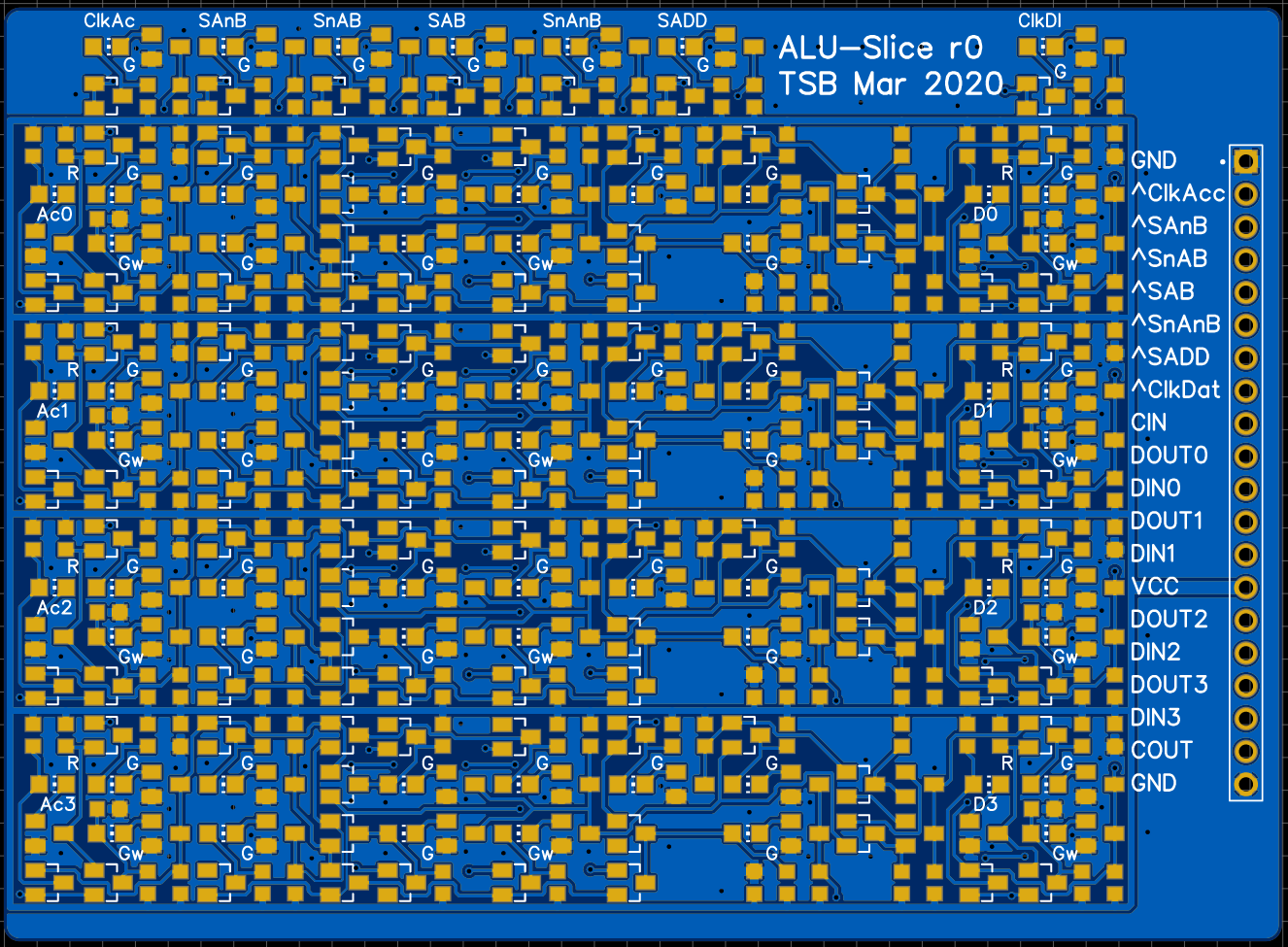 Board render is shown above. The populated boards should arrive in a few weeks.
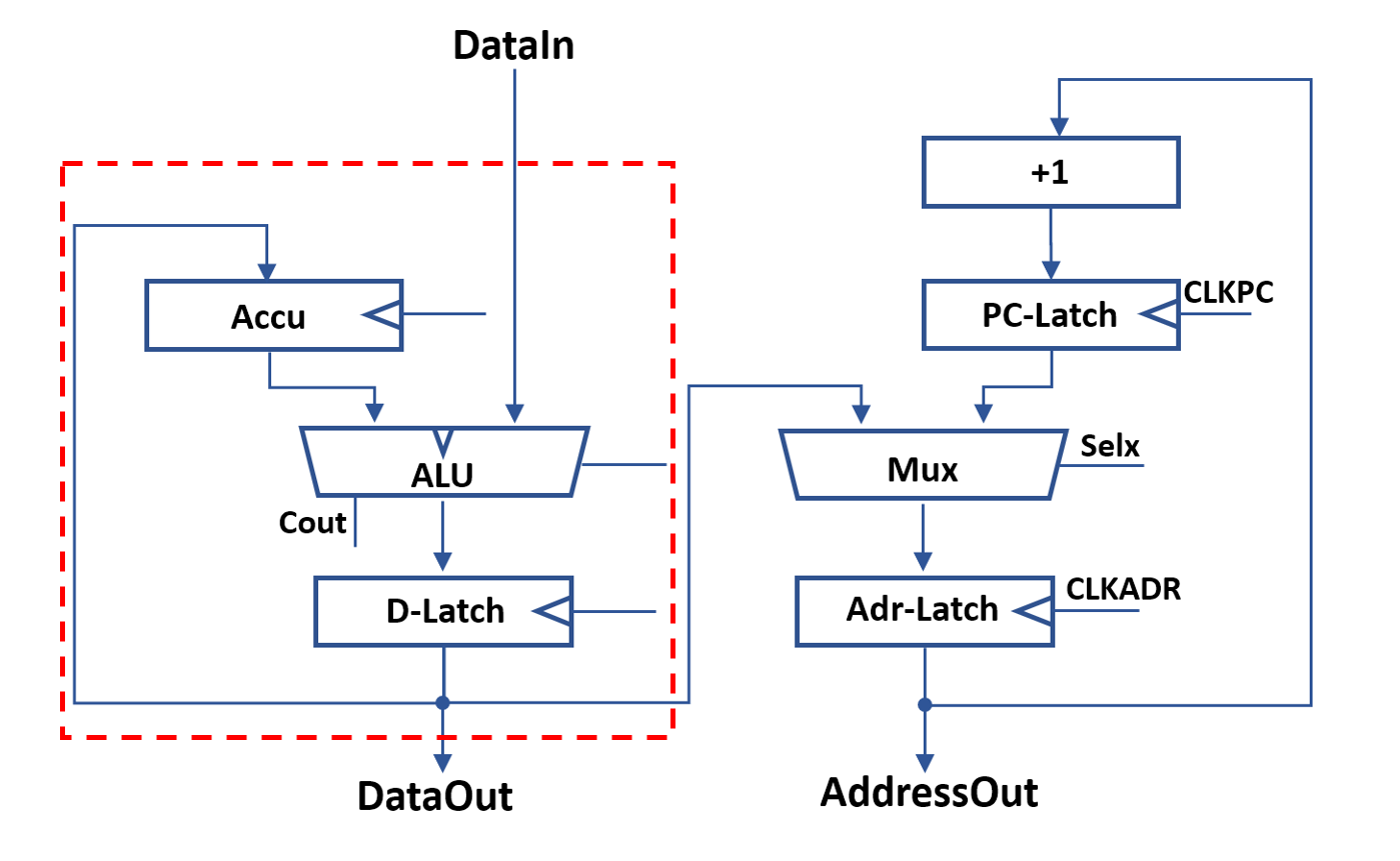
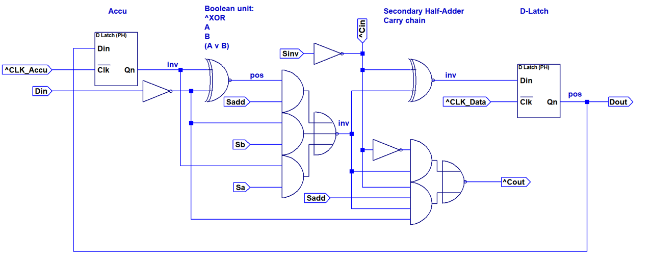 A first implementation option for a single bit of the data-datapath is shown above. This design implements a full adder consisting out of two XNOR2 gates, an inverter and an AOI2 gate. Y=A/Y=B/Y=A OR B is realized with an AOI3 based multiplexer in the first stage. The carry line can be fixed to zero or one by using the Sinv and Sadd control inputs. This allows configuring the second XNOR gate to invert the result, resulting in Y=A NOR B.
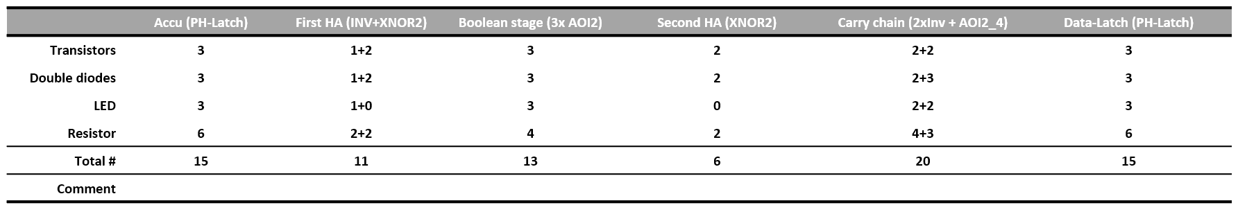 The table above shows the individual component usage. The total part count for this option is 80 per bit.
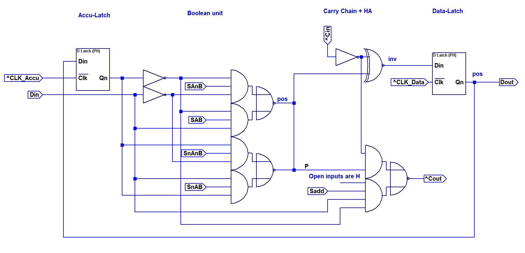
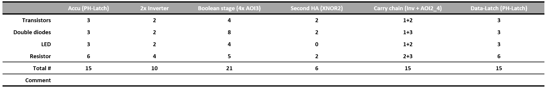 Component requirements are shown in the table above. The total number of components is 82, only two more than the less versalite first option. Therefore I elected to go with this option, since it allows more flexibility.
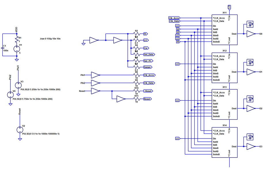
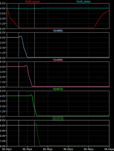 The image above shows carry propagation through all stages. The carry is low active. The carry propagation delay is approximately 11 ns per stage (45 ns total for 4 stages). Although this will propably increase in the real circuit due to more parasitics, it is a very reasonable result and suggests that an acceptably high clockspeed can be achieved even without resorting to a more elaborate carry chain architecture.
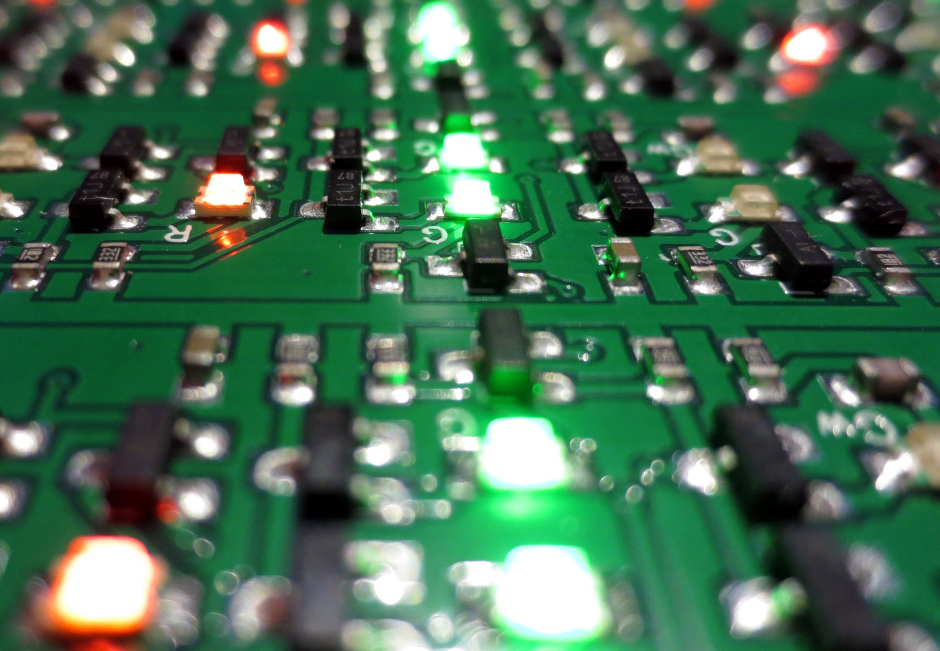 Above you can see the an image of the hardware while it is operating. The red LEDs are part of the low threshold gates in the latches, while all other gates use green LEDs to set the threshold to ~2.3V.
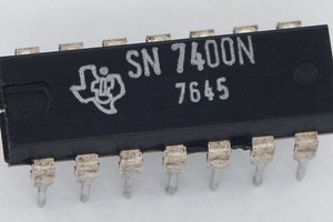
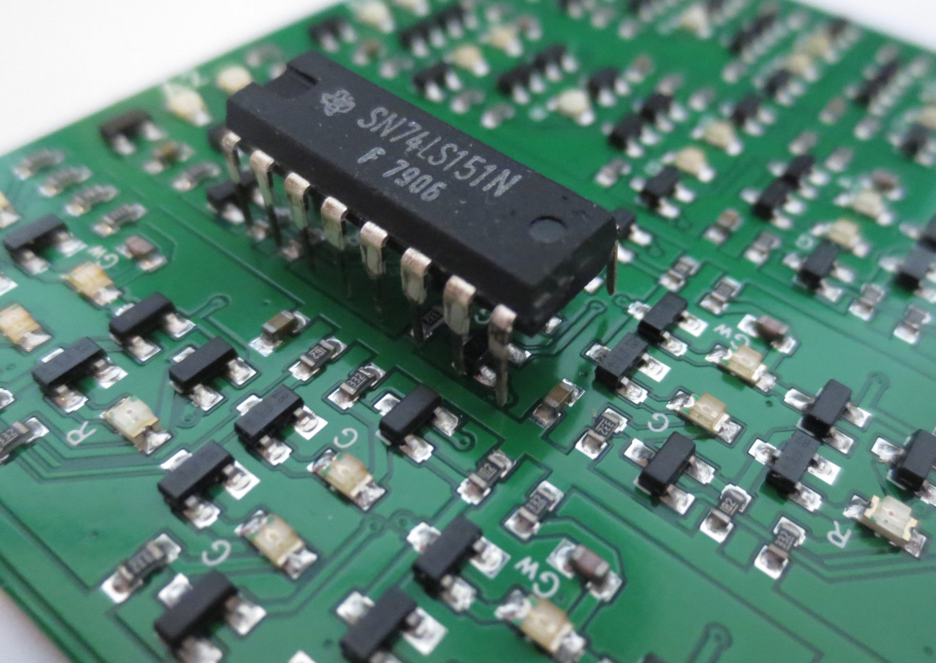 A size comparison with a TTL ICs. The gate density on the PCB in NAND equivalants is slightly lower than what would be achieved with 7400 NAND gates. Something to be addressed for later iterations...
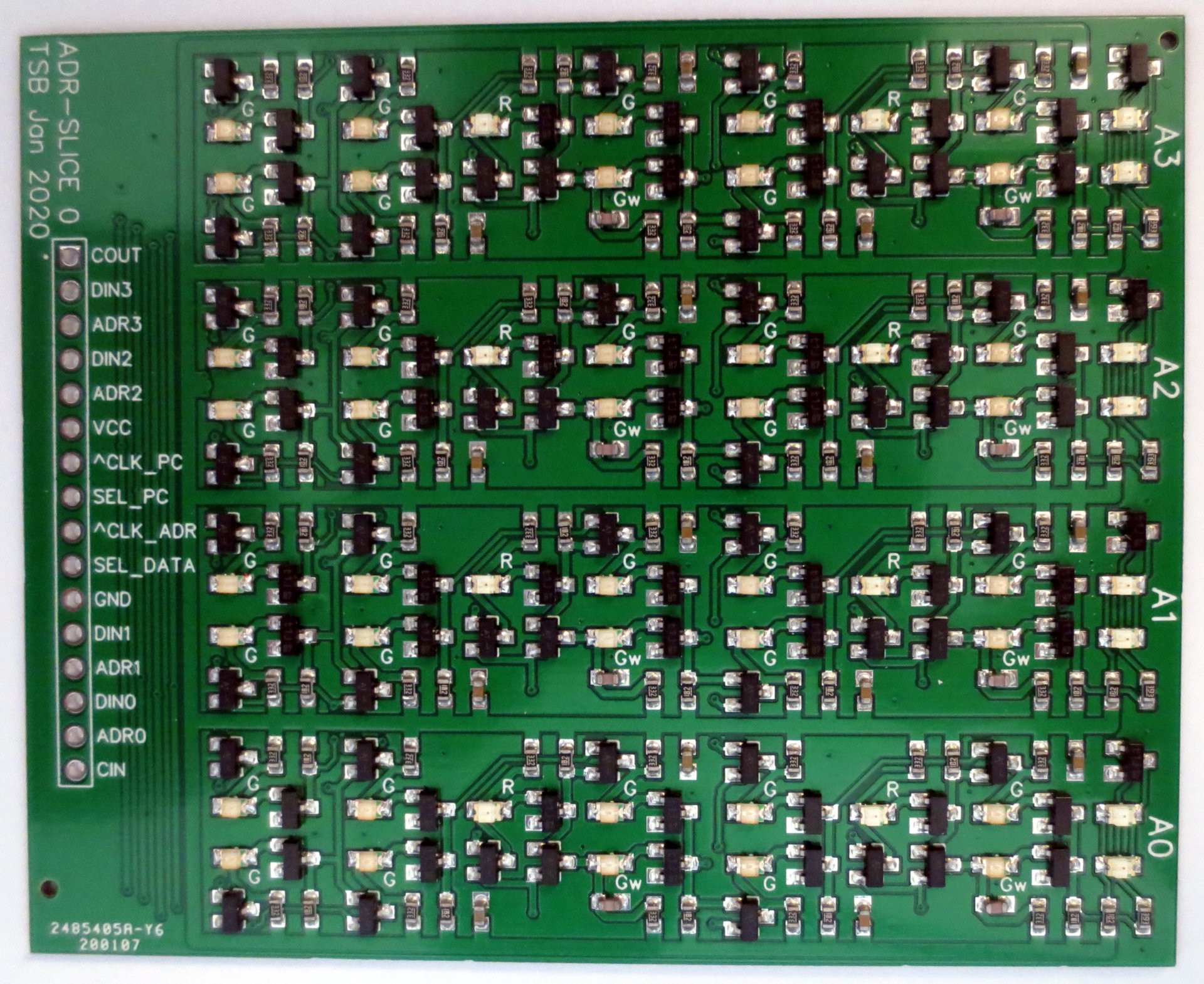 A populated PCB is shown above. Since I am not too fond of placing all those parts by hand, I used an SMD assembly service. The finals stats are: 52 transistors, 48 diodes, 24 capacitors, 56 LEDs and 88 resistors.
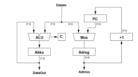
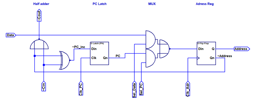 The first design of the adress path is shown above. A half adder is needed to increment the PC. Since the gates are relatevely fast, I used a ripple carry adder. There are two latches for address and PC respectively. An AOI2 gate is used as multiplexer between PC and external address. The address latch can be loaded with zeros by pulling both control inputs of the MUX to low. This can be used to reset the PC.
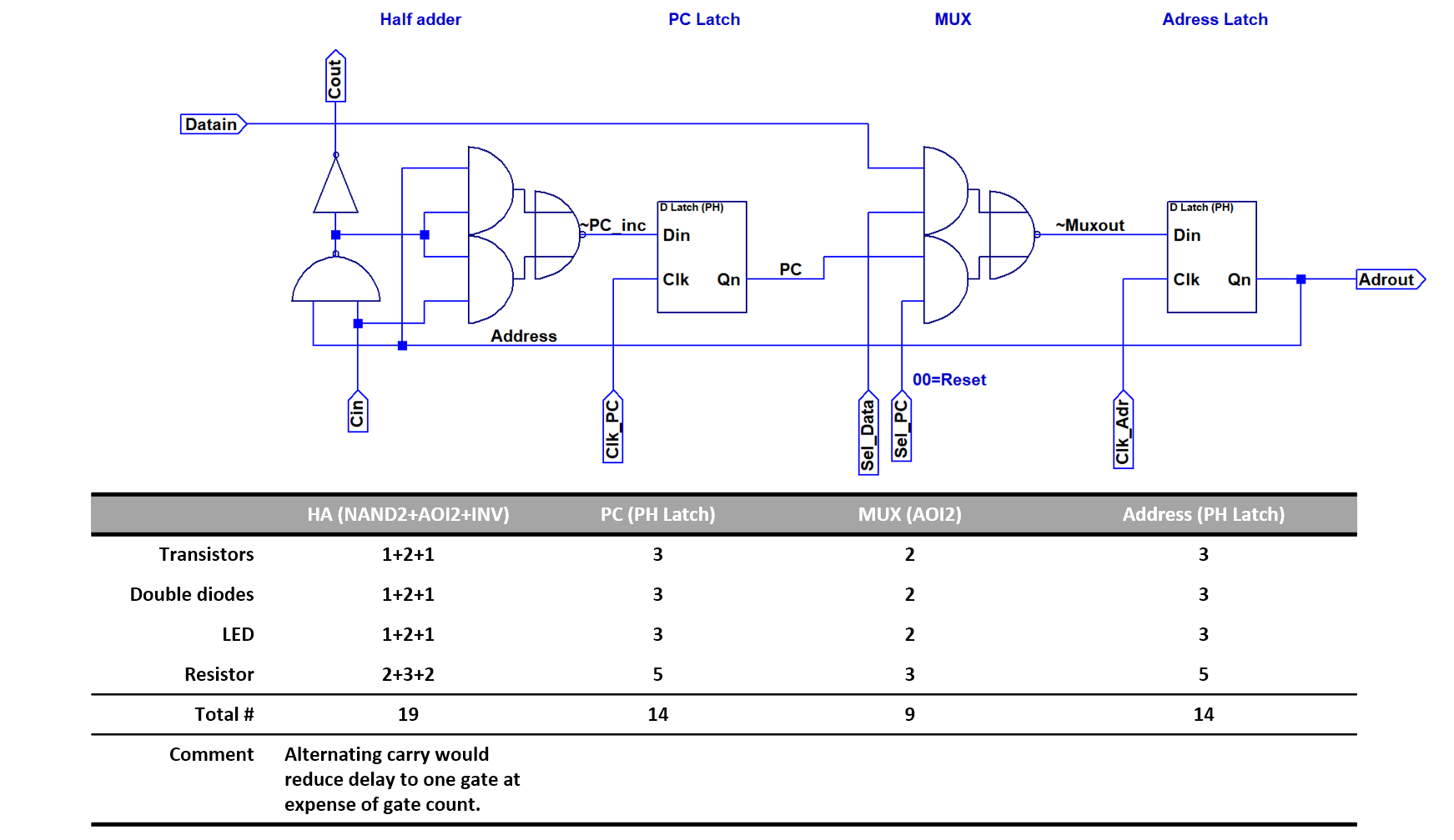 The image above shows the design after some optimization to reduce part count. Each slice consists of 12 NAND equivalents and 56 components total. Note that the carry delay was increased to two gates.
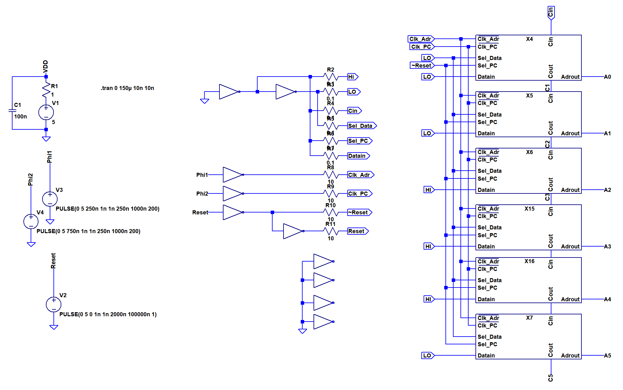
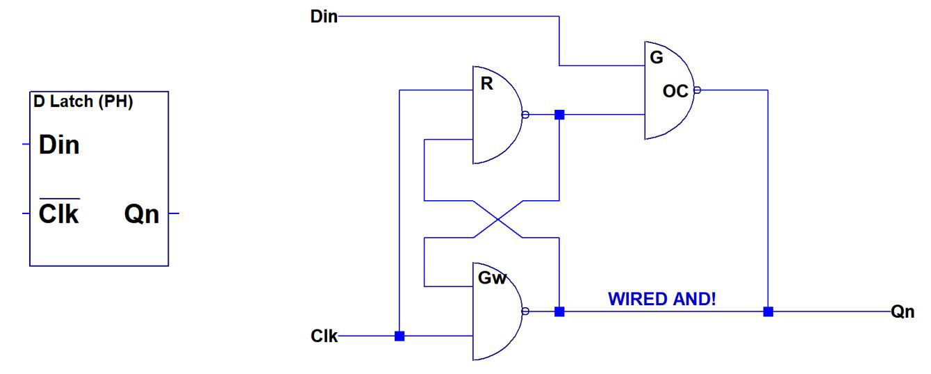 There is also a way to reduce gate count to three by replacing one of the NAND2 gates with a wired AND. This is described in a
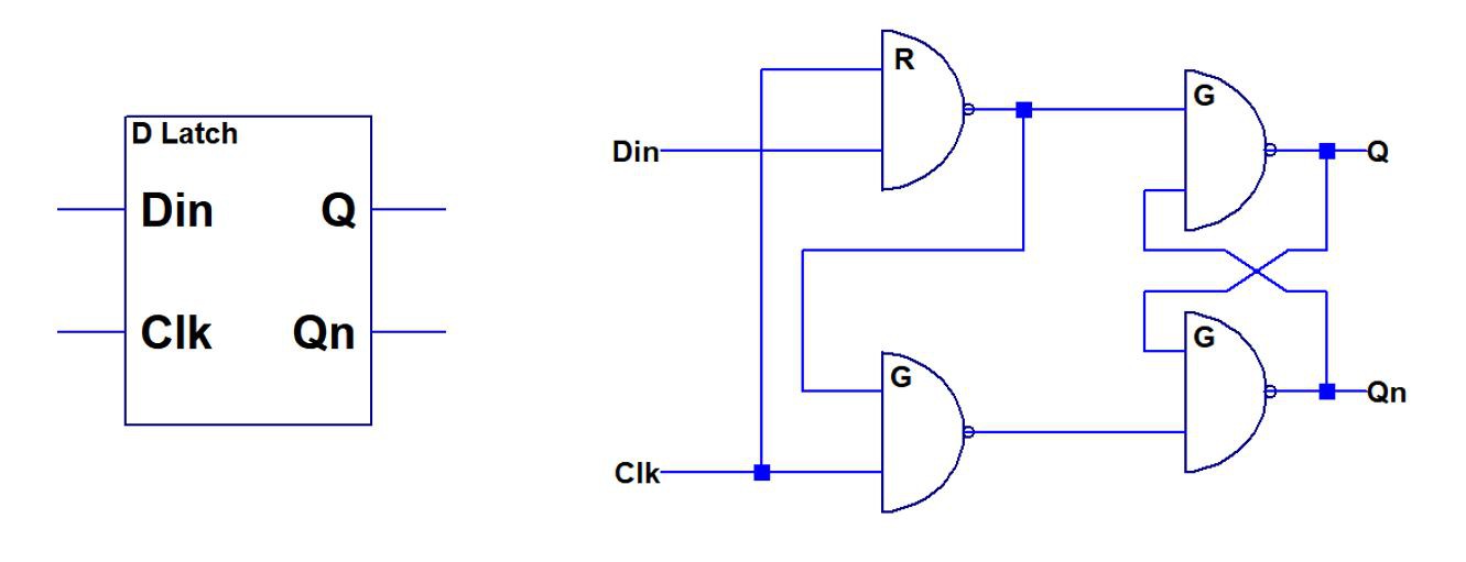
 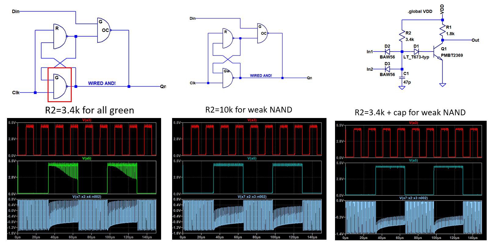 One very important point of learning came out of actually simulating a full design including the latch and observing dynamic operation. To do this, it is necessary to perform a transient simulation in Spice - LTspice was used here.
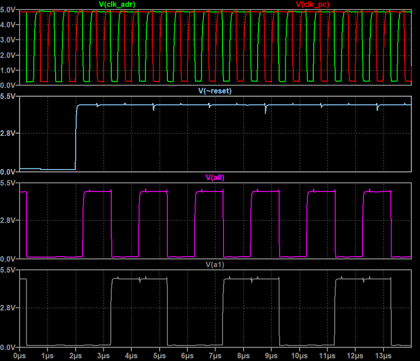


 Yann Guidon / YGDES
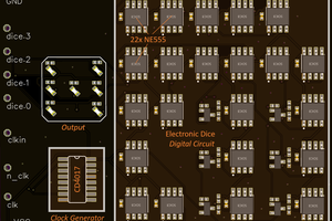
Tim,
I have been following your work for several years.
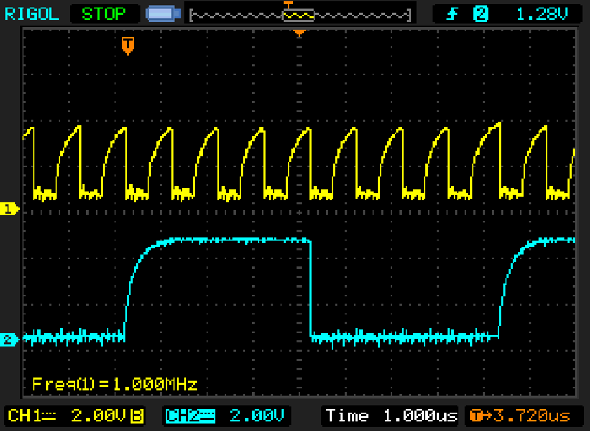
This week I built a 5-stage ring oscillator on a breadboard using BC547B transistors, but with the LEDs included in the base circuit.
Red and green LEDs were mediocre, giving only 40 to 50kHz oscillation.
White LEDs gave an immediate leap to 4MHz and with some tweaking of collector and input pull-up resistor values, I achieved 8.25MHz.
I have measured the forward voltage drop of my white LEDs at 2.5 to 2.7V.
A white LED will still produce useful light output even with just 25uA of current (5V supply and 100K series resistor).
I also breadboarded an edge triggered D-type flopflop. It's 6 transistors and 18 signal diodes, but clocks cleanly with a 1MHz clock - even on a breadboard.
I am currently working on a discrete transistor 16-bit CPU using bit-serial architecture. This will keep the transistor count below 1000.
The pcb area of my 3 input NAND gate is 100mm2, so the final design pcb will be about 320 x 320 mm.