danjovic
-
Assembling the Digi:Arka->Pad
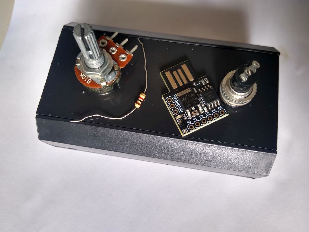
05/16/2021 at 16:43 • 0 commentsSome pictures of the assembly. First thecomponents
![]()
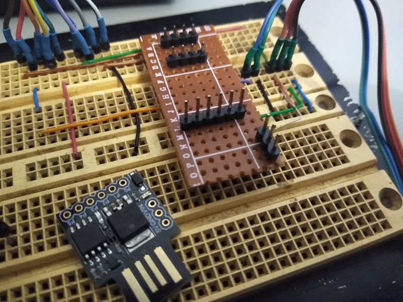
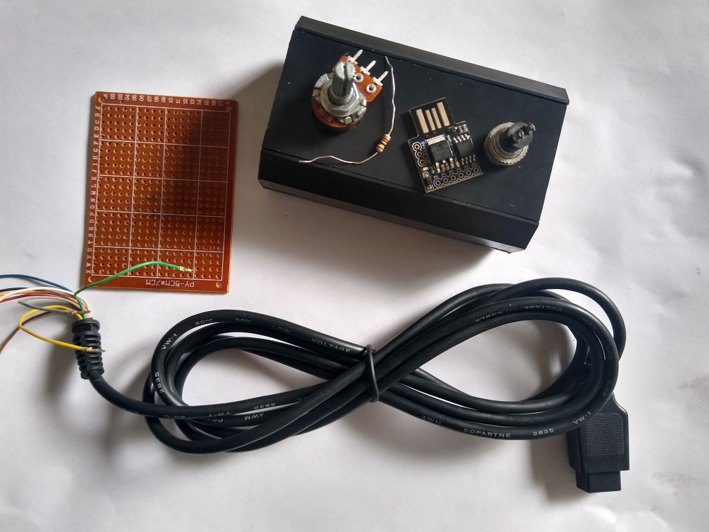
Another picture of the components. I have considered to use the Veroboard but haven't did that now. Maybe on the next project.
![]()
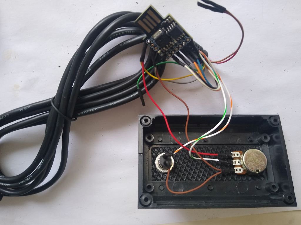
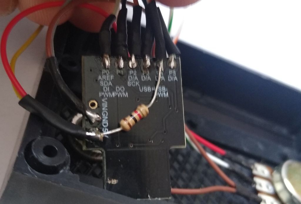
The resistor is soldered under the board, from VCC to PB4
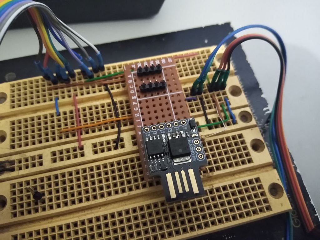
![]() Everything wired
Everything wired![]()
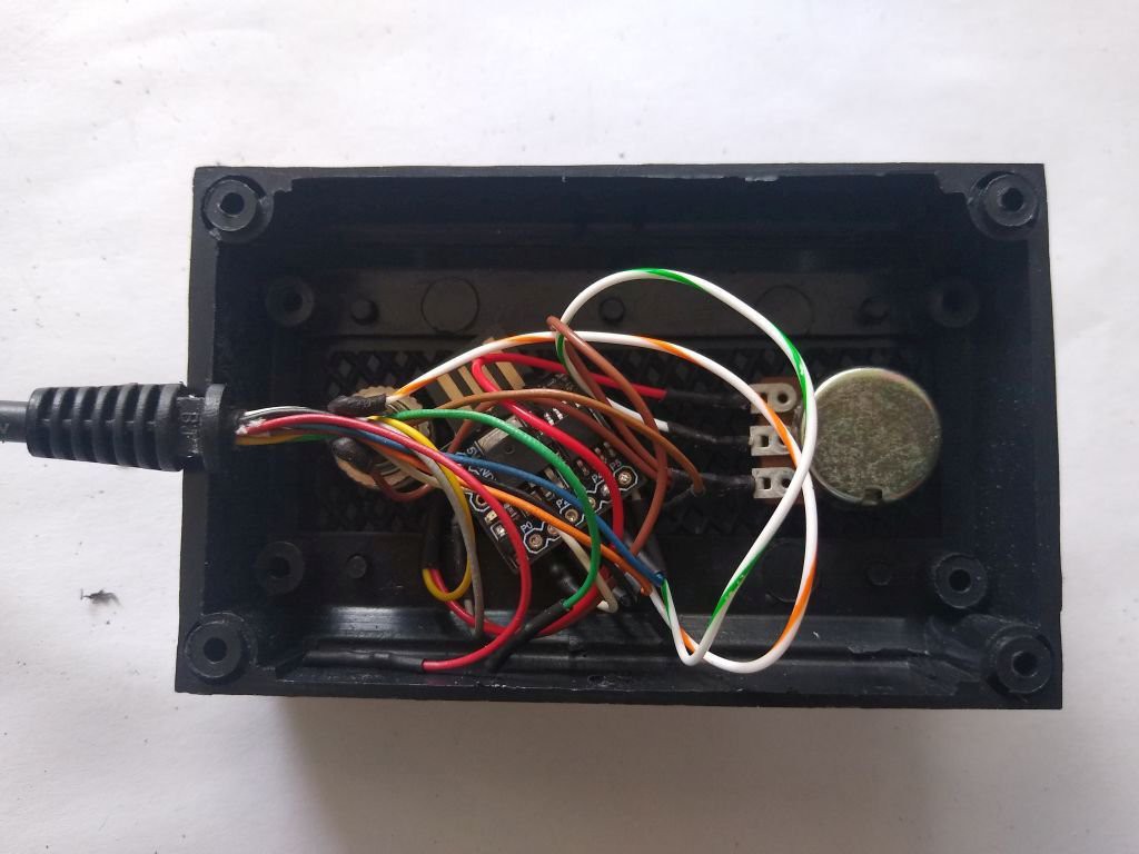
Wires organized
![]()
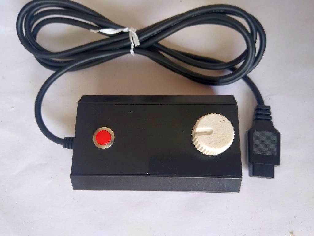
Unit assembled and closed
![]()
-
Demo Videos
04/05/2020 at 16:55 • 0 commentsRecorded some videos to demonstrate the project:
-
Prototype with Digispark
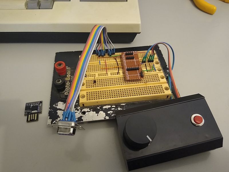
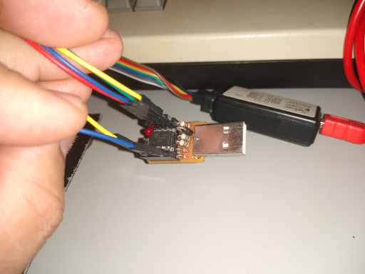
04/05/2020 at 15:04 • 0 commentsHere you are the prototype that runs on Digi-Spark board.
![]()
I have used a DIY adapter board to assemble the prototype on a protoboard.
![]()
![]()
-
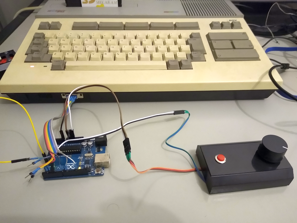
Prototype with UNO
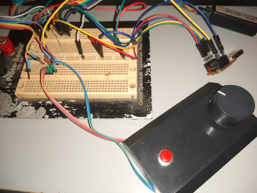
04/05/2020 at 03:03 • 0 commentsThat's the prototype built with Arduino UNO. The potentiometer and button were borrowed from #Vaus Arkanoid Paddle Clone project.
-
Temporization for Standard Paddle.
04/05/2020 at 02:13 • 0 commentsAccording to MSX Red book:
"Each paddle is basically a one-shot pulse generator, the length of the pulse being controlled by a variable resistor. A start pulse is issued to the specified joystick connector via PSG Register 15. A count is then kept of how many times PSG Register 14 has to be read until the relevant input times out. Each unit increment represents an approximate period of 12 µs on an MSX machine with one wait state."
When you do the math, 256 increments of 12us yelds: 12us*256 = 3072us.

Timing for Potentiometer at minimum: 12.125us 
Timing for Potentiometer at maximum: 3058us Mission Accomplished!
A quick note, though.
Pulse pins coming from MSX triggers a Pin Change interrupt on the AVR. At the beginning of the ISR it was necessary to read the state of the line to check whether the pin change has been a rising or a falling edge.
The DigitalRead() function was taking too long to execute, longer than the 4.7us that the input pulse lasted.
After the code was changed to read the AVR input register (PINB) directly the Standard paddle function worked fine.
#define SOChigh() PINB&(1<<1) // Fast digital reading // // Pin change interrupt driven by SOC (Start of Conversion) pin (8) - PULSE // ISR(PCINT0_vect) { // if (SOChigh() ) { //Rising edge? ... ... -
Extended Version
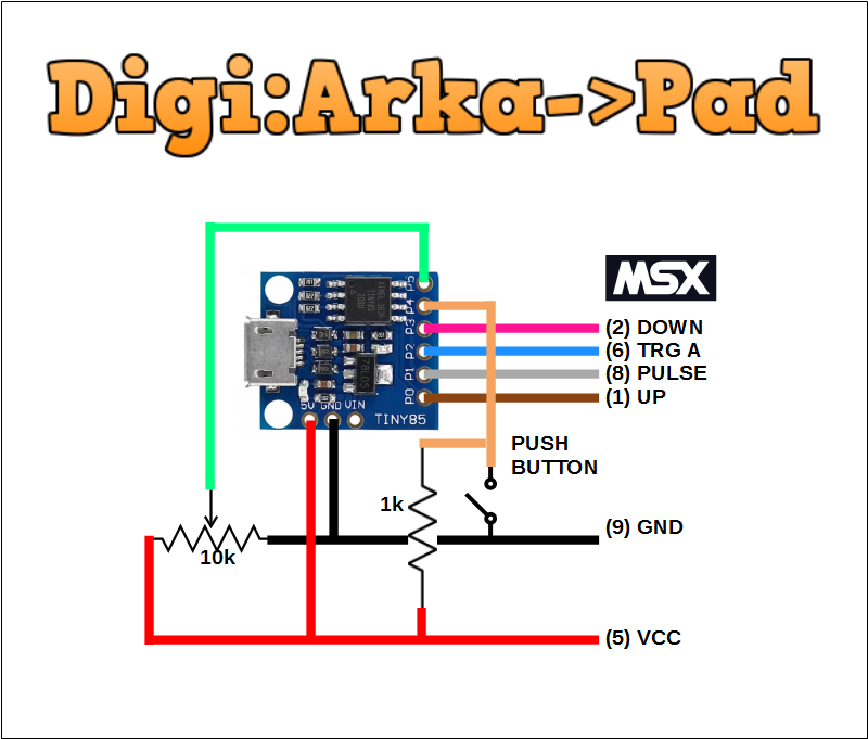
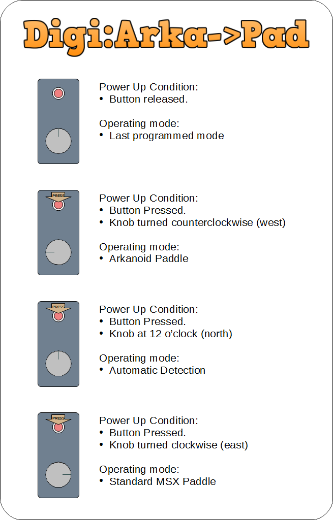
04/05/2020 at 01:41 • 0 commentsI have just released an extended version named Digi:Arka->Pad with the following features:
- Support for Standard Paddles
- Selectable operating modes:
- Automatic
- MSX Standard
- Arkanoid
![]()
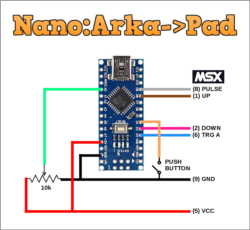
Also added support for other Arduino boards (spinoff versions)
- Nano
![]()
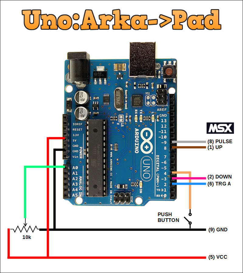
- UNO
![]()
Mode programming is performed by holding the button pressed at power up and stored in internal EEPROM.
Selected mode depends upon the position of the potentiometer.
![]()
-
More on glitches
04/02/2020 at 22:10 • 0 commentsI have performed more waveform captures and noticed that the occurrence of glitches depends upon what is connected to pin 8.
- Without anything connected to the pins 8 and 6 - No glitches
- With #Vaus Arkanoid Paddle Clone connected - No glitches
- With #Digi:Arka connected - Glitches
- With a 1k resistor from pin 8 to VCC - No glitches
- With a 1K resistor from pin 8 to GND - Glitches
![]()
-
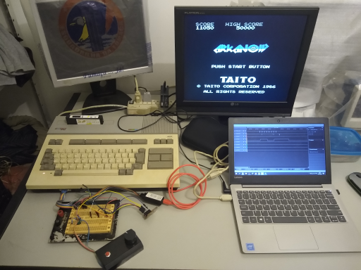
Presenting the prototype
04/02/2020 at 01:52 • 0 commentsSome pictures of the prototype
![]()
Overview ![]()
DIY digispark clone ![]()
Pot and button borrowed from another project -
Glitches, and how to get rid of them -Part II like a pro!
04/02/2020 at 01:31 • 0 commentsI have studied the nature of the glitch for this particular device and verified the following fact:
- Glitches are caused by MSX. No doubt on that;
- Glitches occur only when CLOCK signal change its state;
- Glitches occur simultaneously to the change in CLOCK signal.
then I have added another facts:
- CLOCK signal triggers INT0 on AVR;
- PULSE signals either real or glitches triggers Pin Change Interrupt on AVR;
Then just as I was considering the last fact.....
- External Interrupts have priority over Pin Change Interrupts!
The solution slapped me in the face!
"CLEAR PIN CHANGE INTERRUPTS AT THE END OF EXTERNAL INTERRUPT SERVICE"
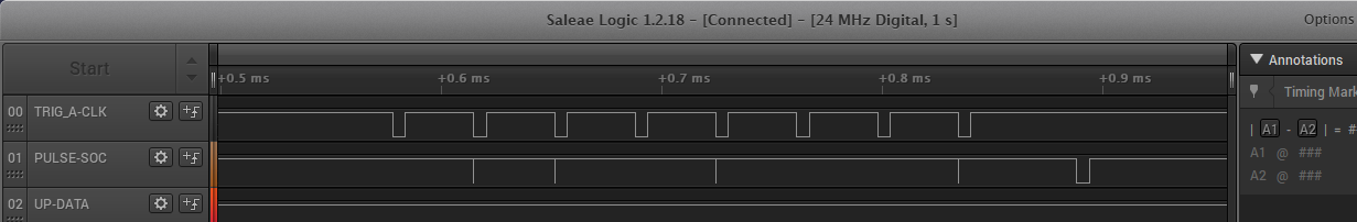
And that was done...
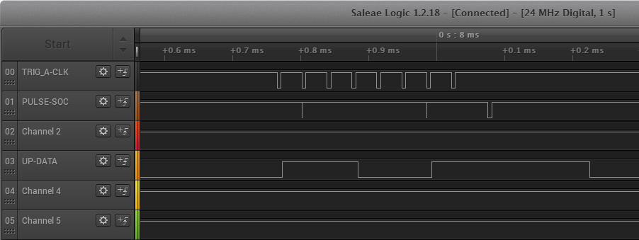
//
// External Interrupt driven by Clock pin (6)
//
ISR(INT0_vect) {
  // output a new bit
  if (shiftRegister & (1 << MSBIT)) {
    pinMode(DATA, INPUT_PULLUP);
  } else {
    digitalWrite(DATA, LOW);
    pinMode(DATA, OUTPUT);
  }
  // pre-shift next bit
  shiftRegister <<= 1;

  GIFR |= (1<<PCIF );   // <- De-glitch in a single instruction!
}
The result can be seen below. Glitches still appear but they do not cause any harm !
![]()
-
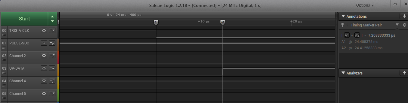
Latency
04/02/2020 at 00:08 • 0 commentsMeasured the latency of the interrupts from falling edge of CLOCK signal until the level at output changes state: 7.2us
![]()
Such latency did not cause any problem on Arkanoid game but just for curiosity it is equivalent to 26 Tstates of an MSX running at 3.579MHz.
Digi:Arka
Dirt-cheap Vaus paddle clone for MSX - Now supports Standard Paddles too.
 Everything wired