RC ORDNANCE
-
ENGINE
11/15/2020 at 10:31 • 0 commentsFULL TRHOTTLE !
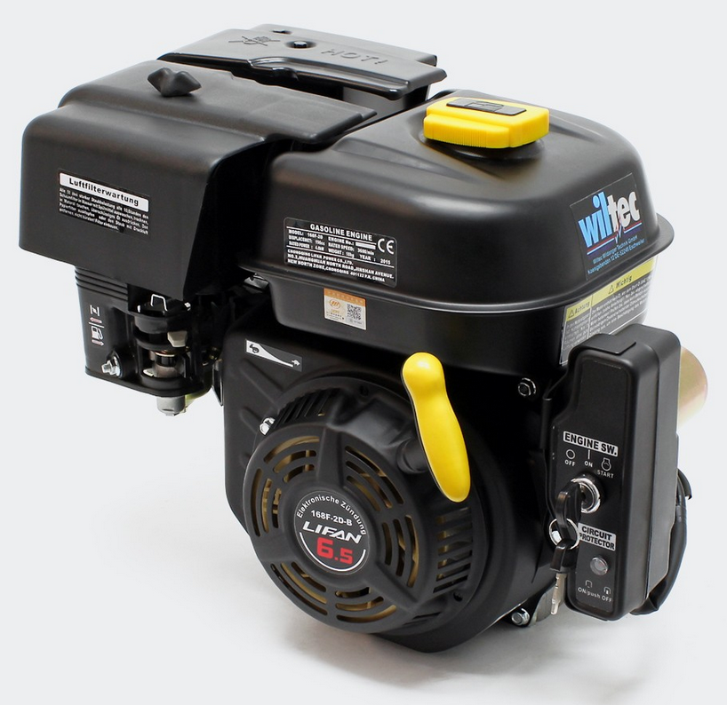
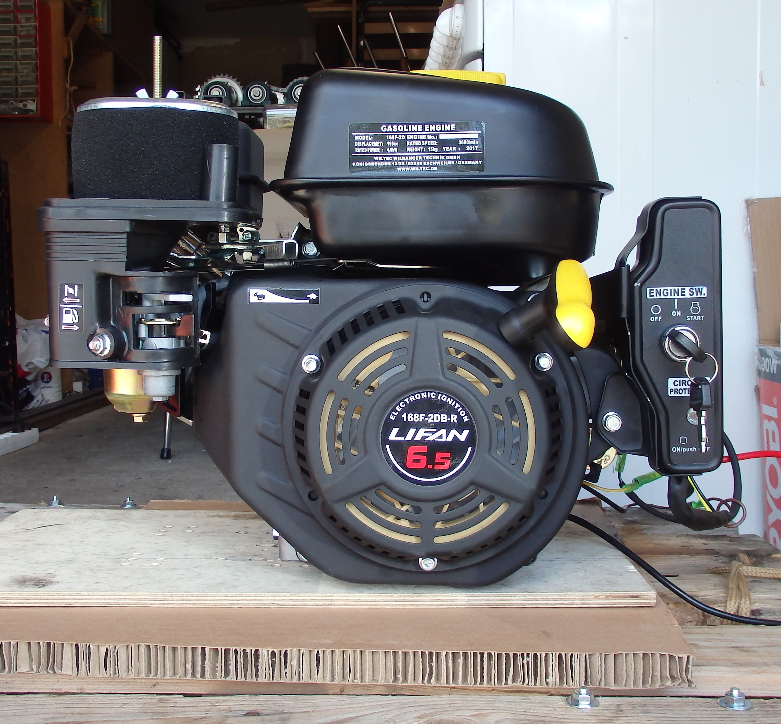
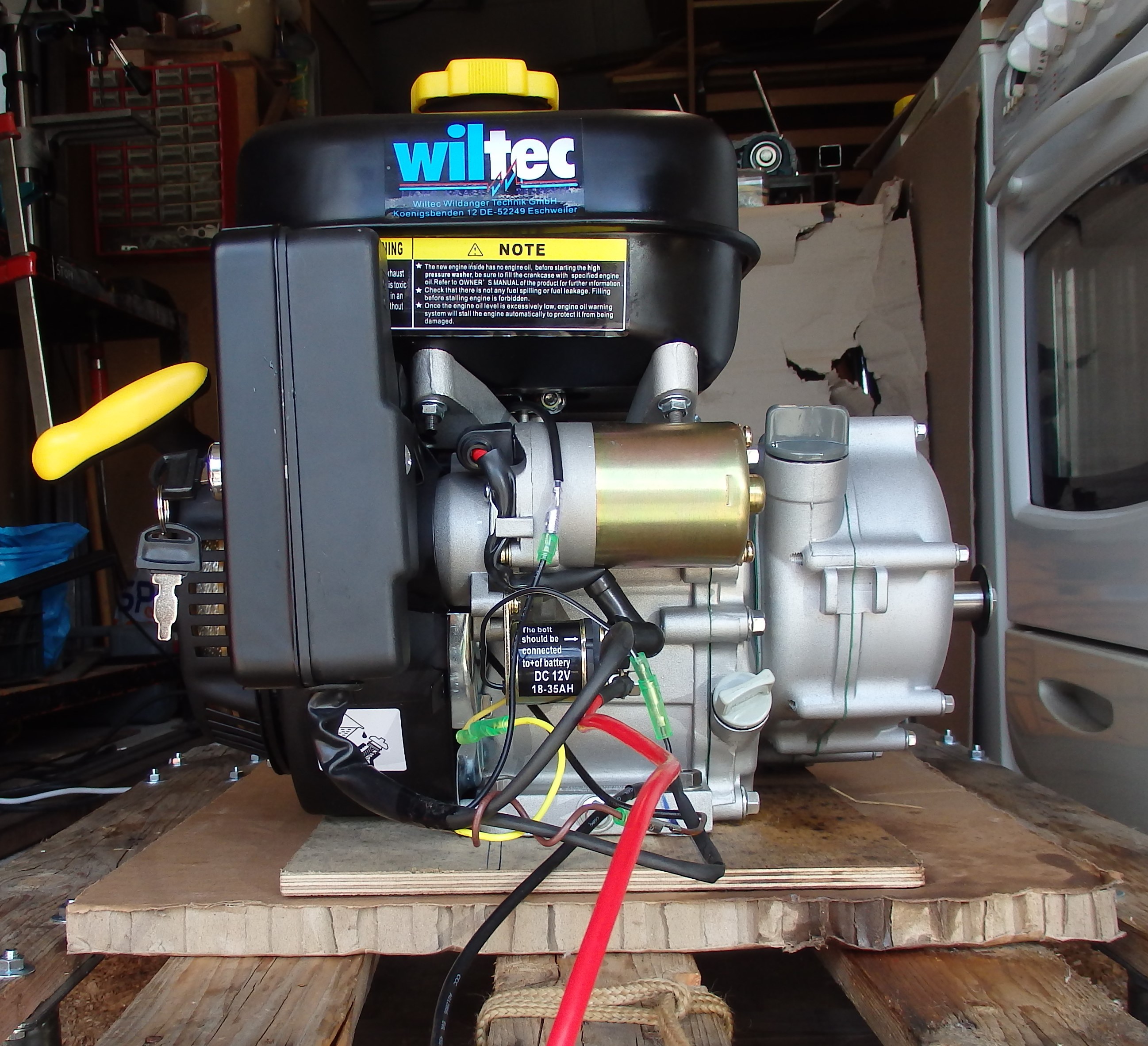
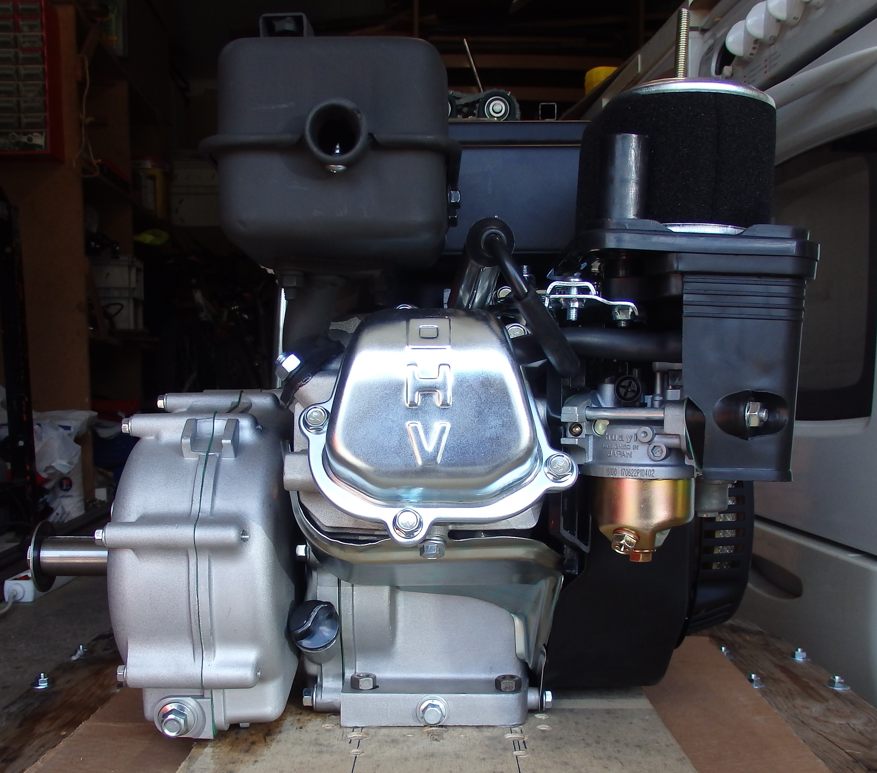
I wanted to use an IC engine as main power source from the very begining.
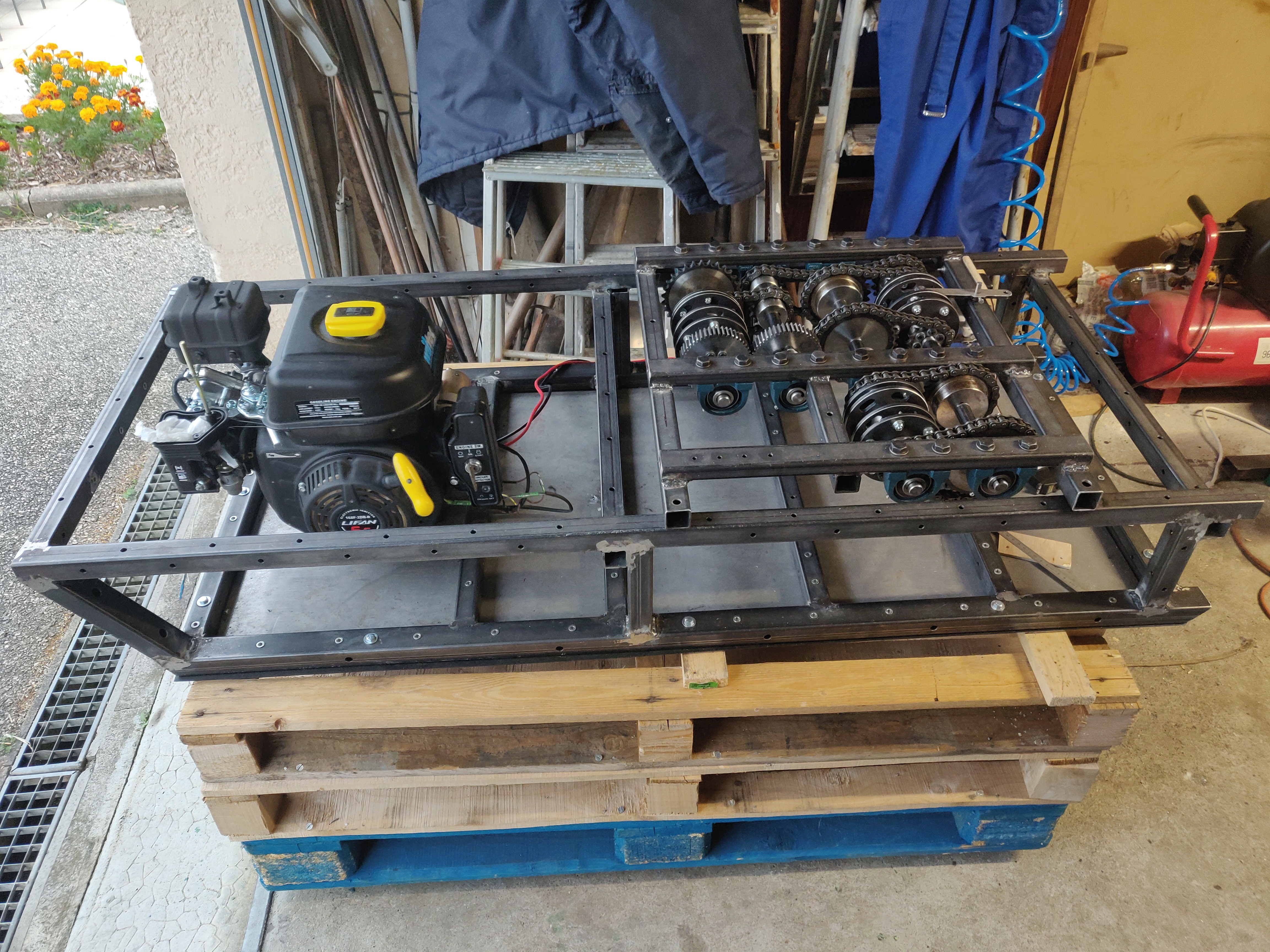
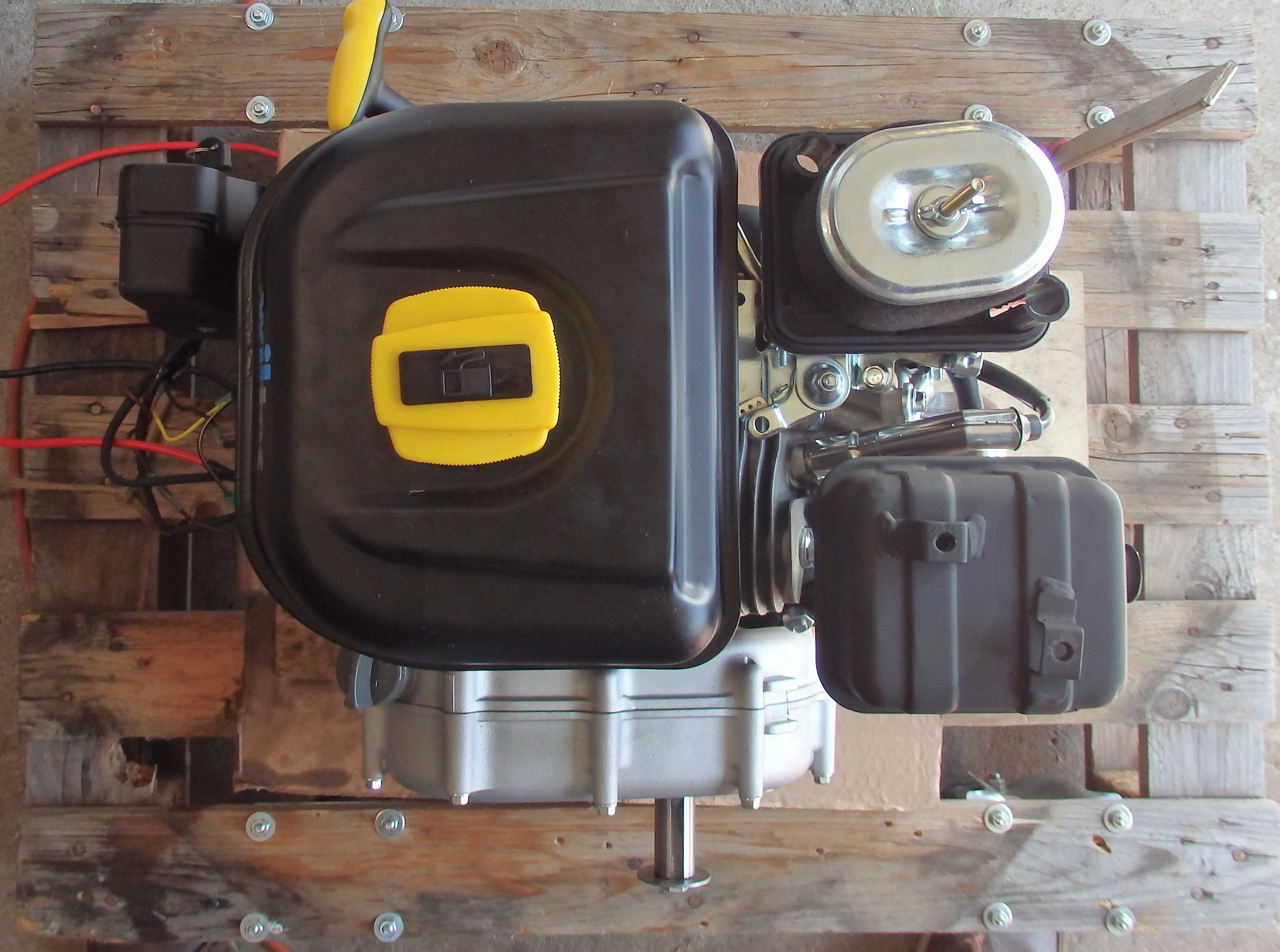
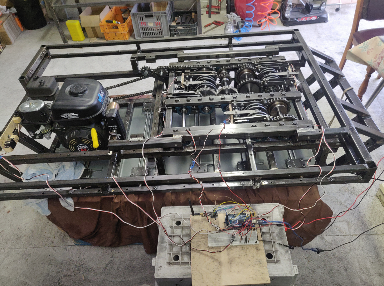
I chose a 196cc 4 800W (6.5hp) 4 stroke engine. It includes both manual and electric start. The engine is equipped with a centrifugal clutch, which simplifies my work a lot. It is a "LIFAN 168F-2D-B" engine.
VIDEO
![]()
![]()
![]()
![]()
![]()
![]()
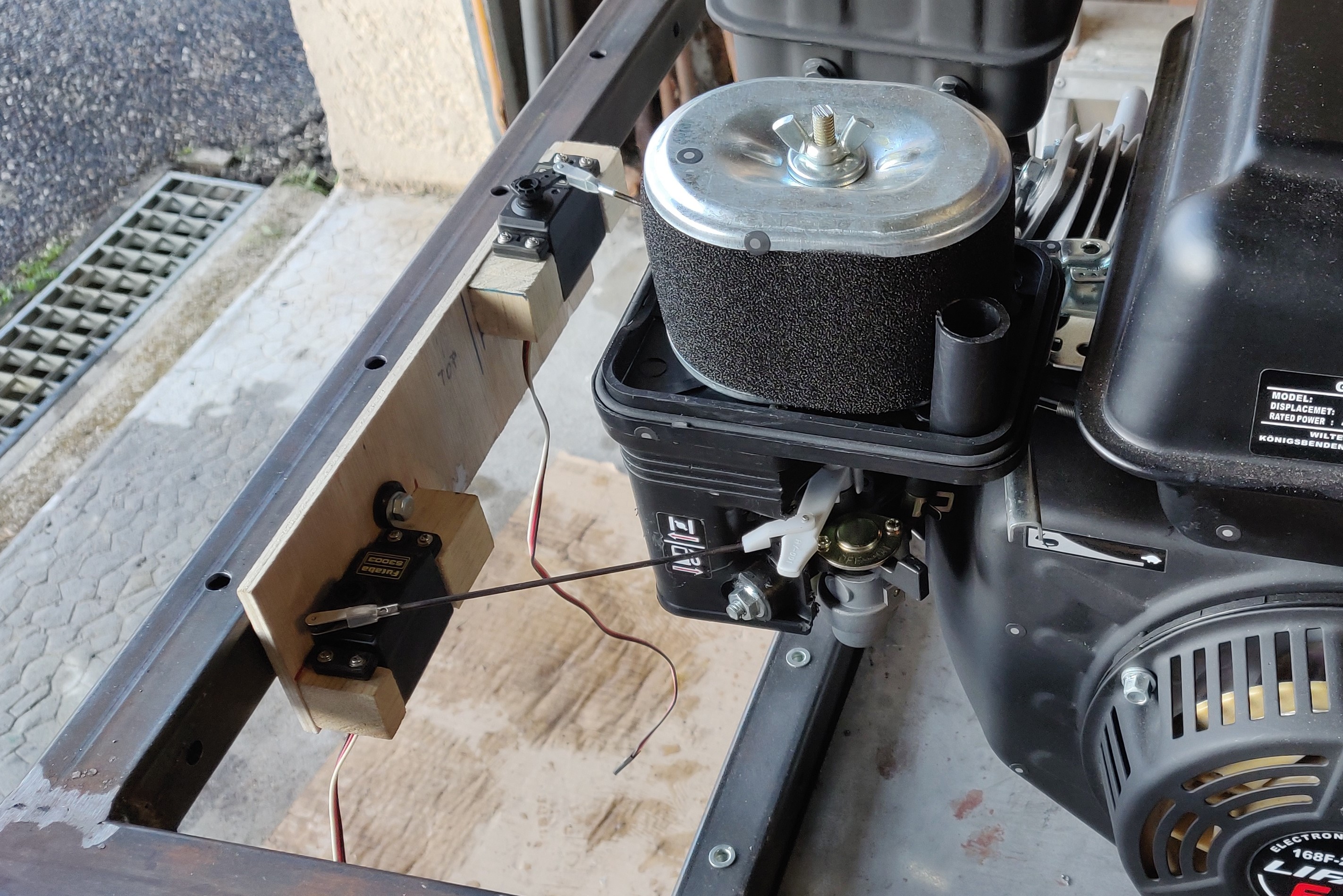
Servos were quite easy to add and worked very well right away. 3kg.cm torque proves to be enough.
closest servo : choke
other servo : throttle![]()
The engine will be fixed on 4 anti vibration mounts. I also had to add a couple profils to stiffen the base plate, so that it doesn't bend under engine's torque. TO BE CONTINUED....
-
SUSPENSION
11/14/2020 at 21:36 • 0 commentsON THE BOUNCE !
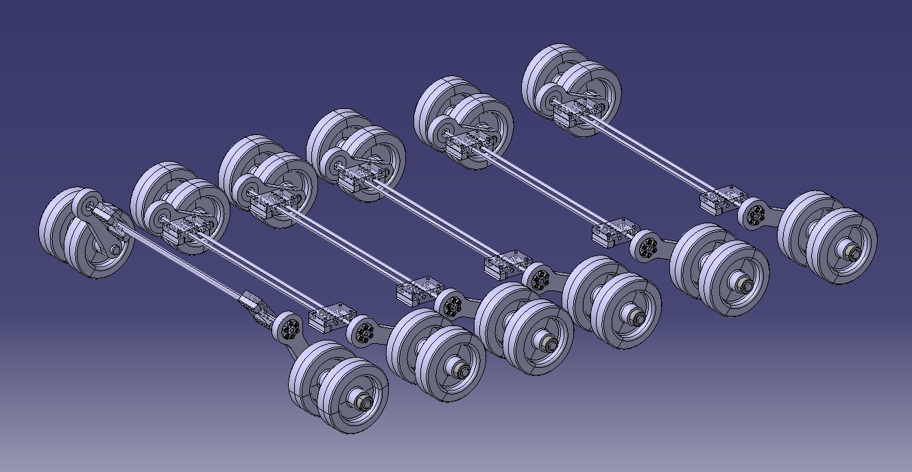
I will be using the torsion bar concept : This is a very compact and low maintainance suspension system.
![]()
I wil try to make an adjustable system, since I don't know the exact weight of the finished tank. It can also be useful to modify the initial strain to change the suspension behaviour if needed.
![]()
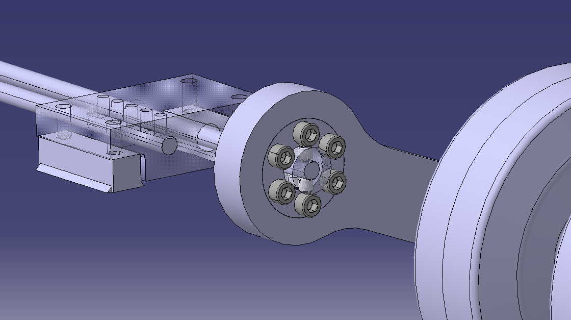
The locking assembly will allow to modify the initial strain of the suspension ![]()
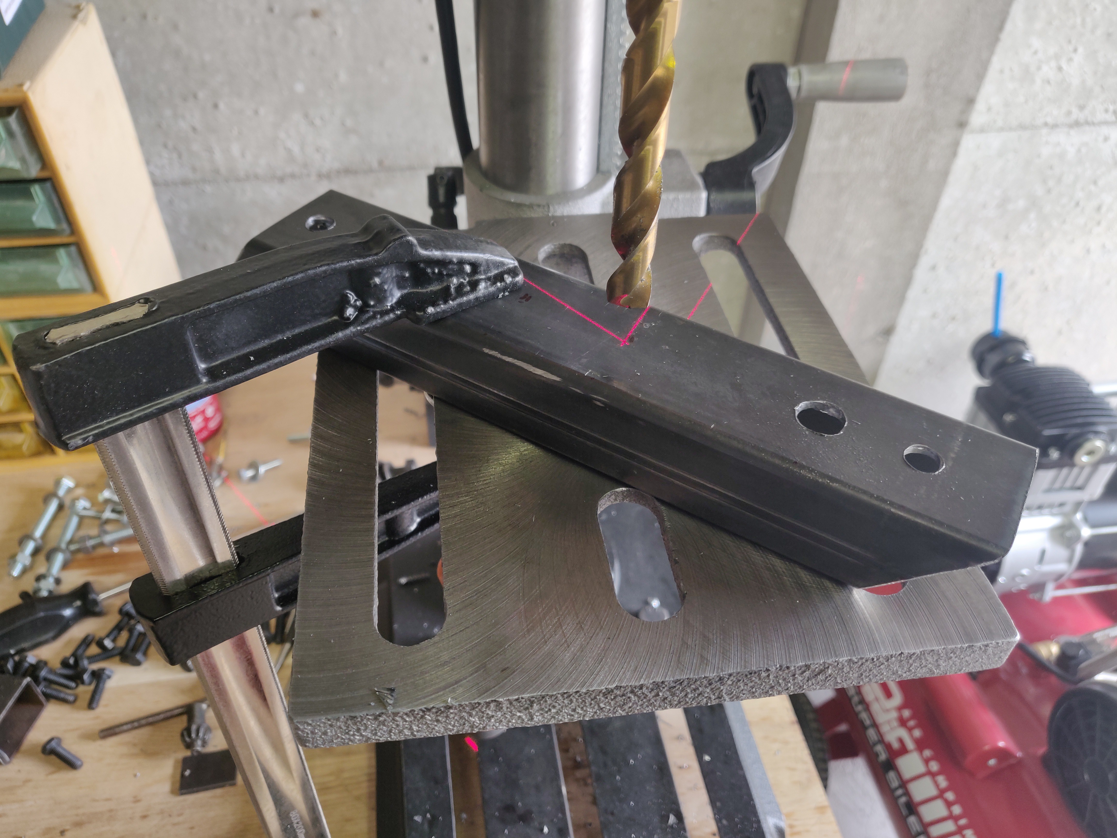
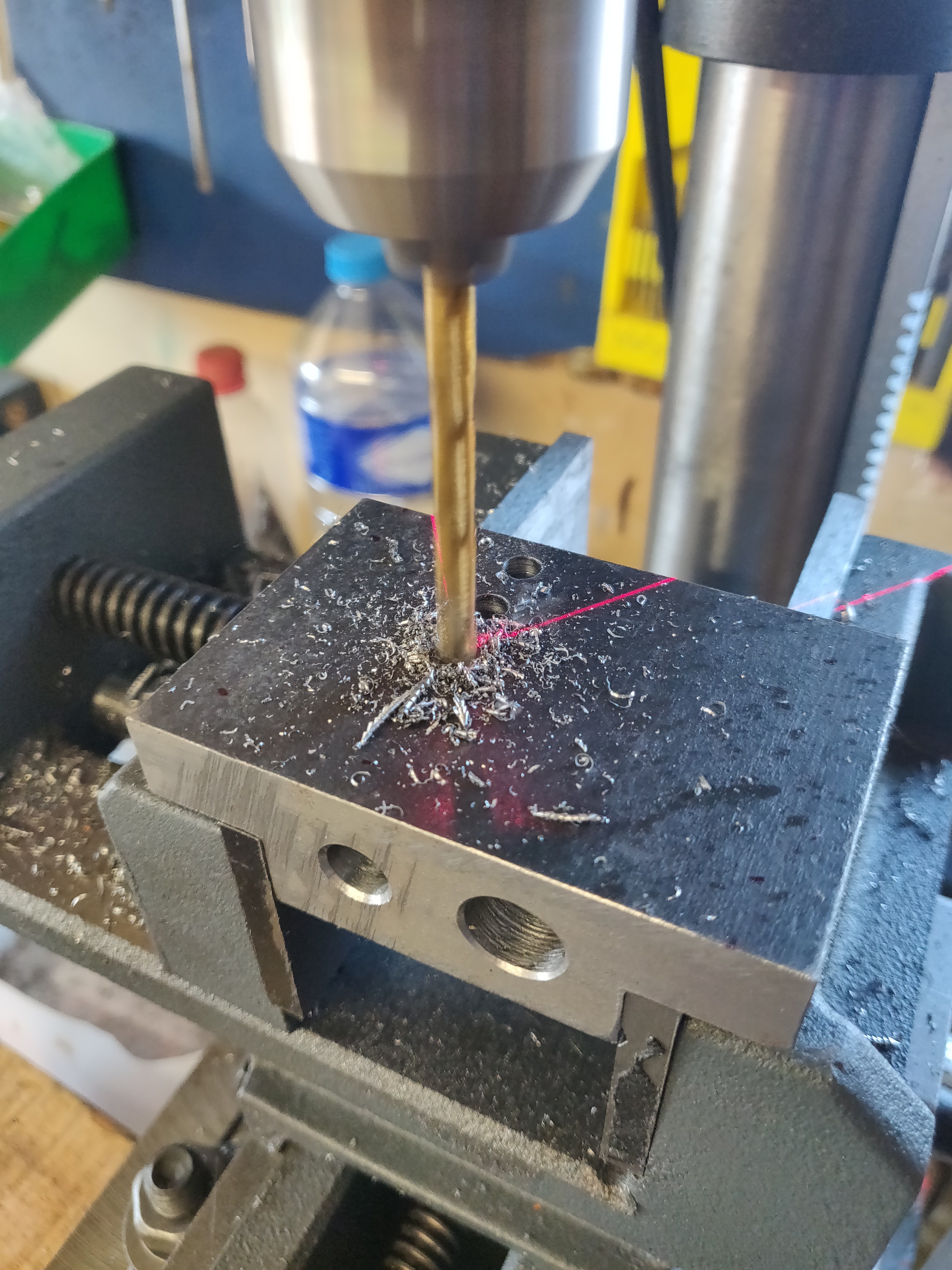
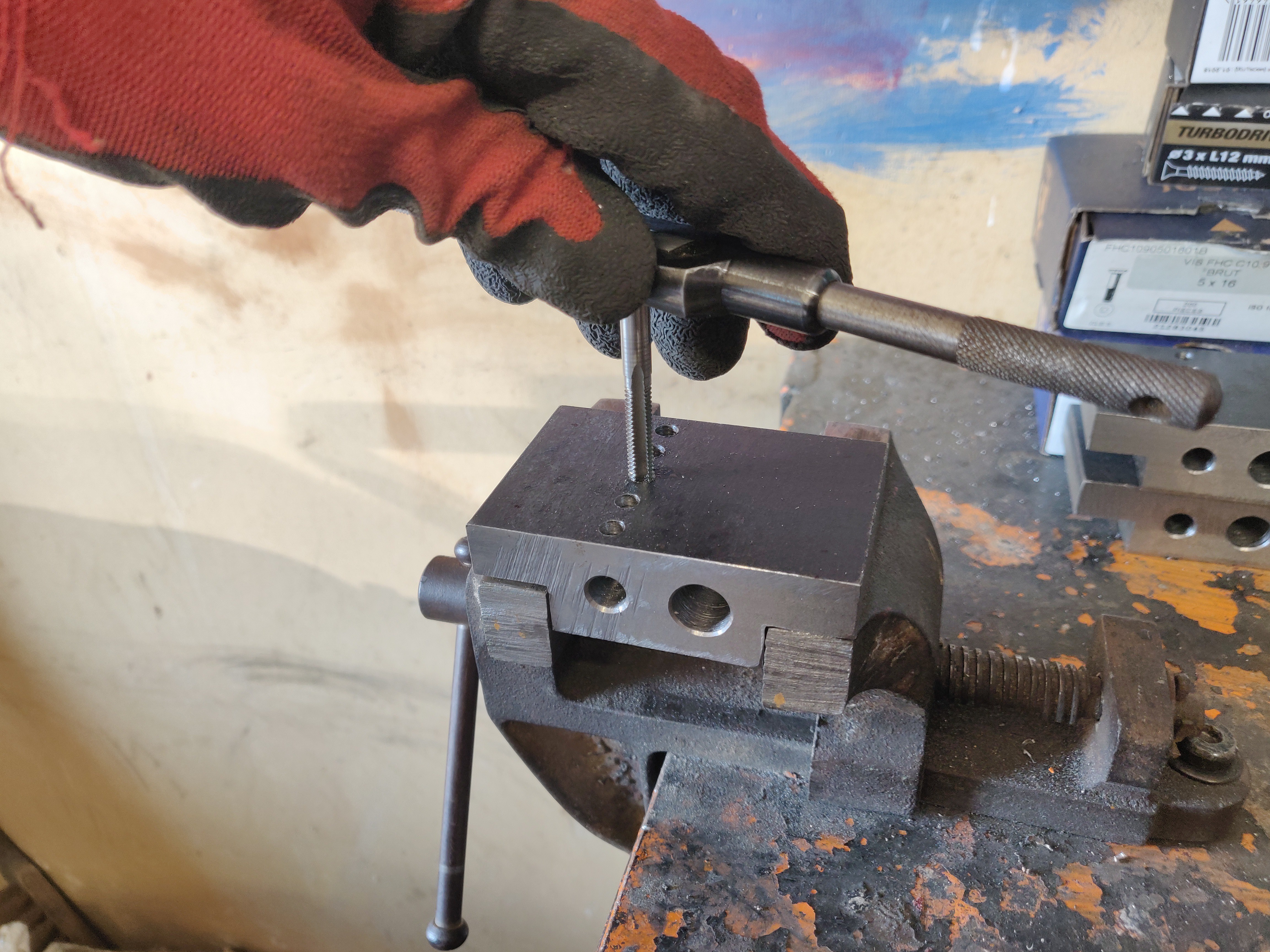
A lot of holes to drill again... ![]()
... and to tap ! ![]()
11 more to go ! ![]()
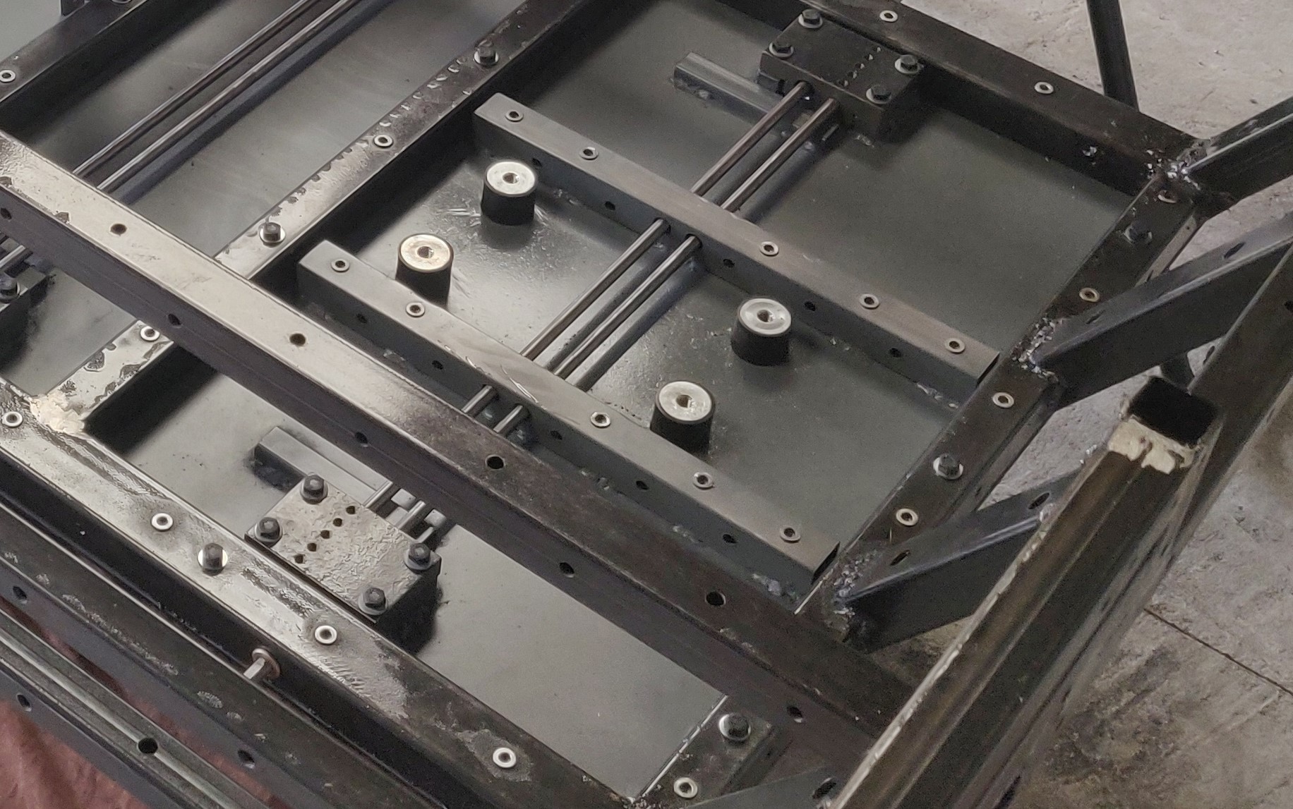
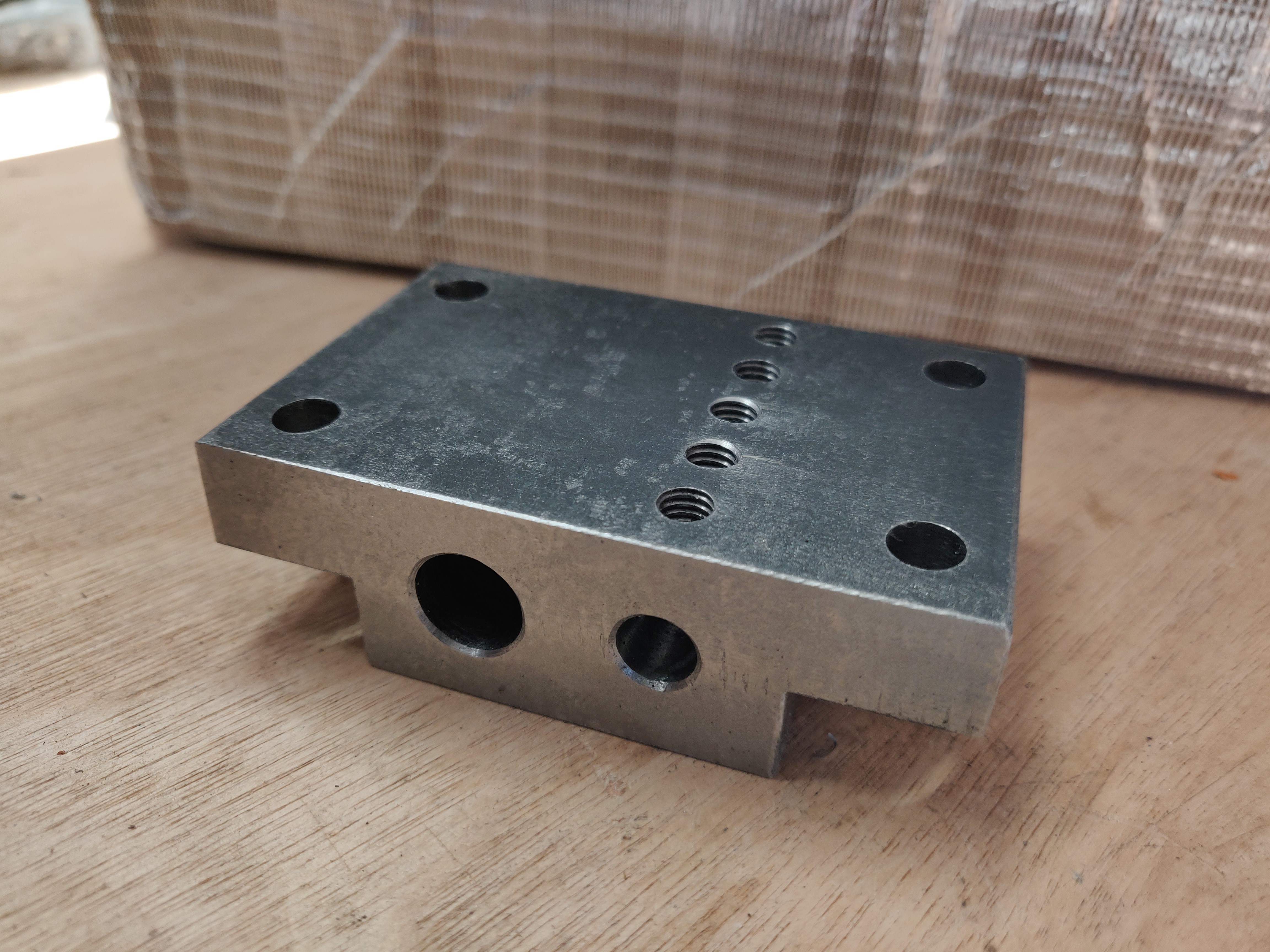
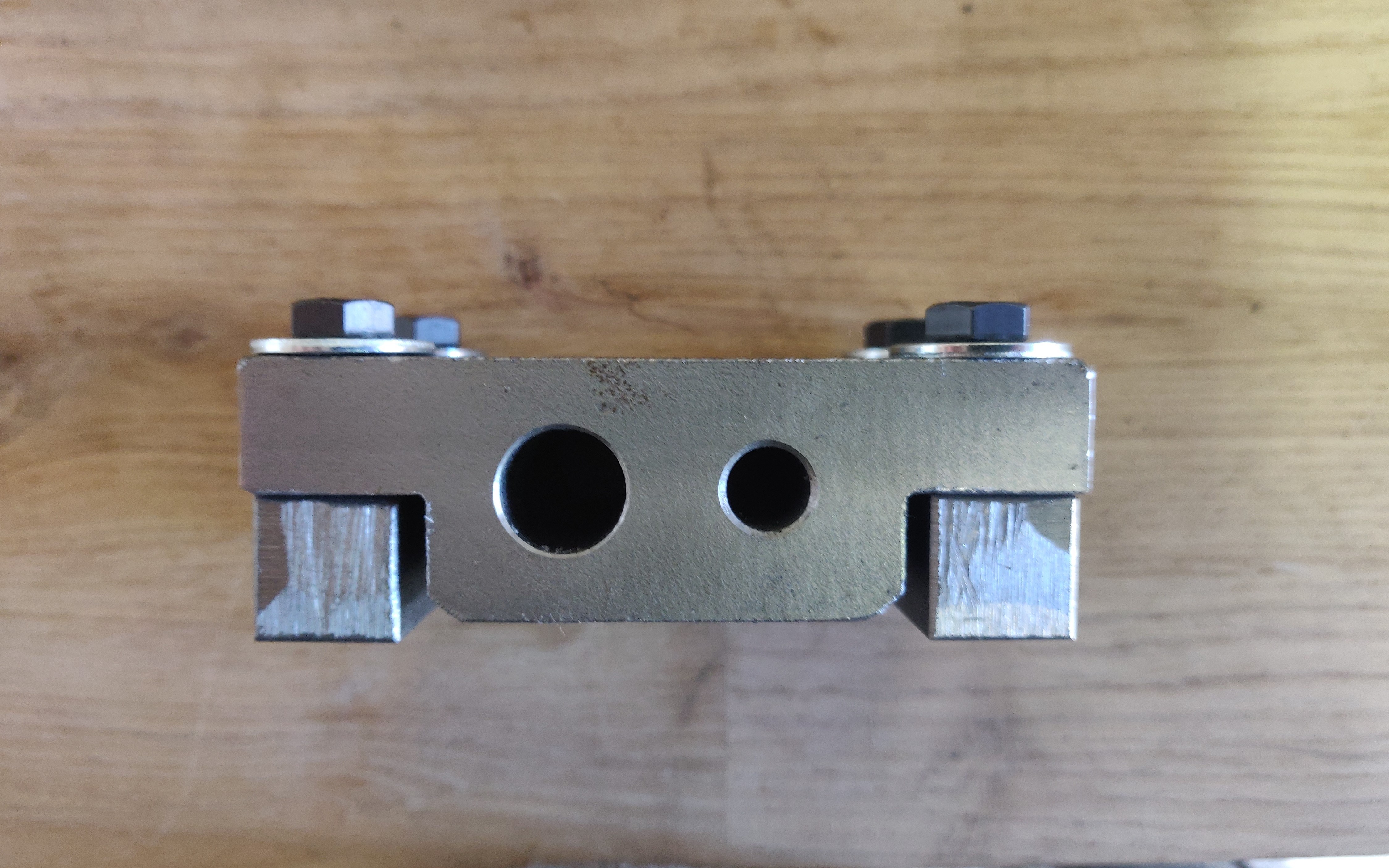
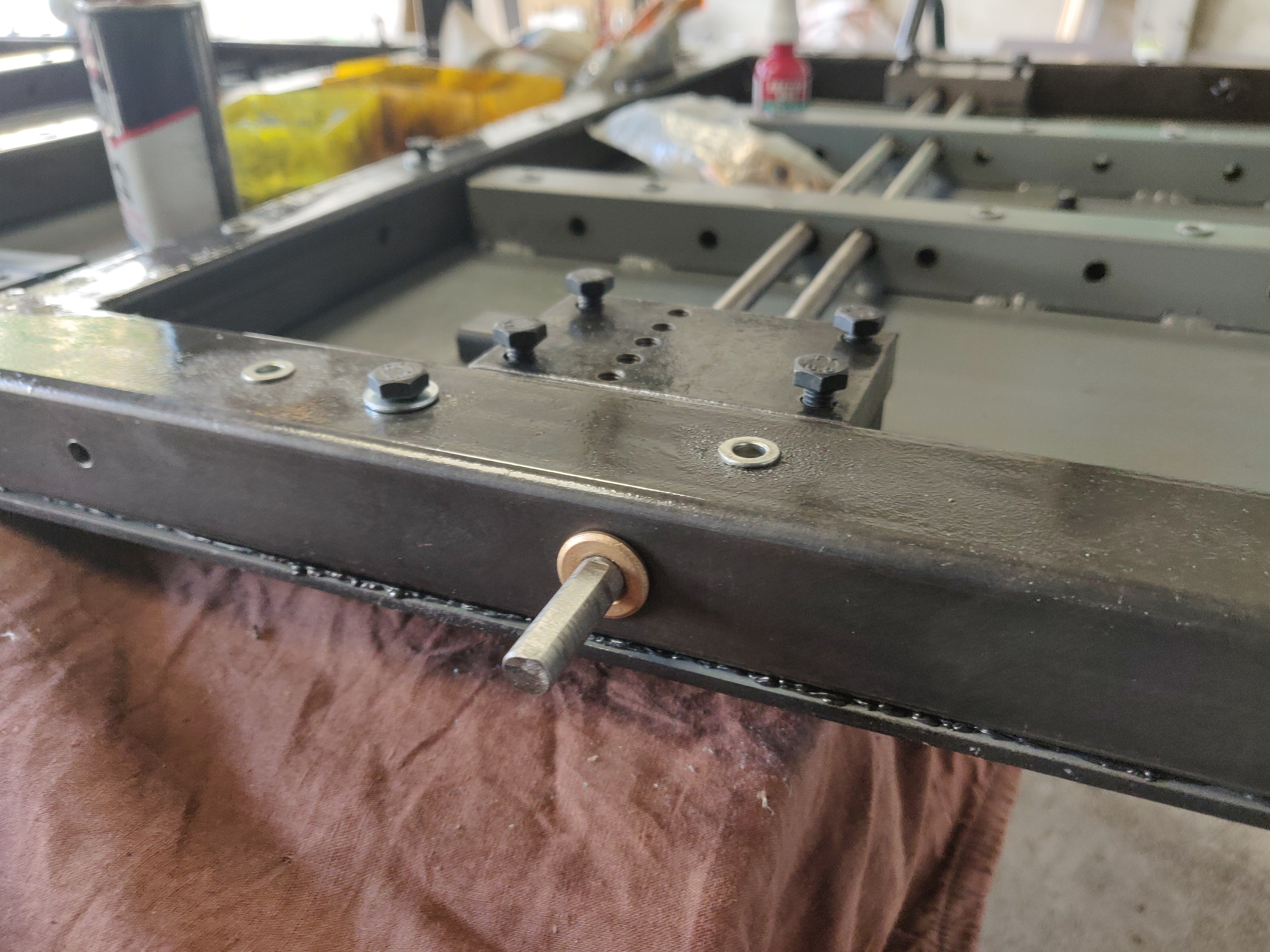
The suspension blocks will be screwed to their mounts... ![]()
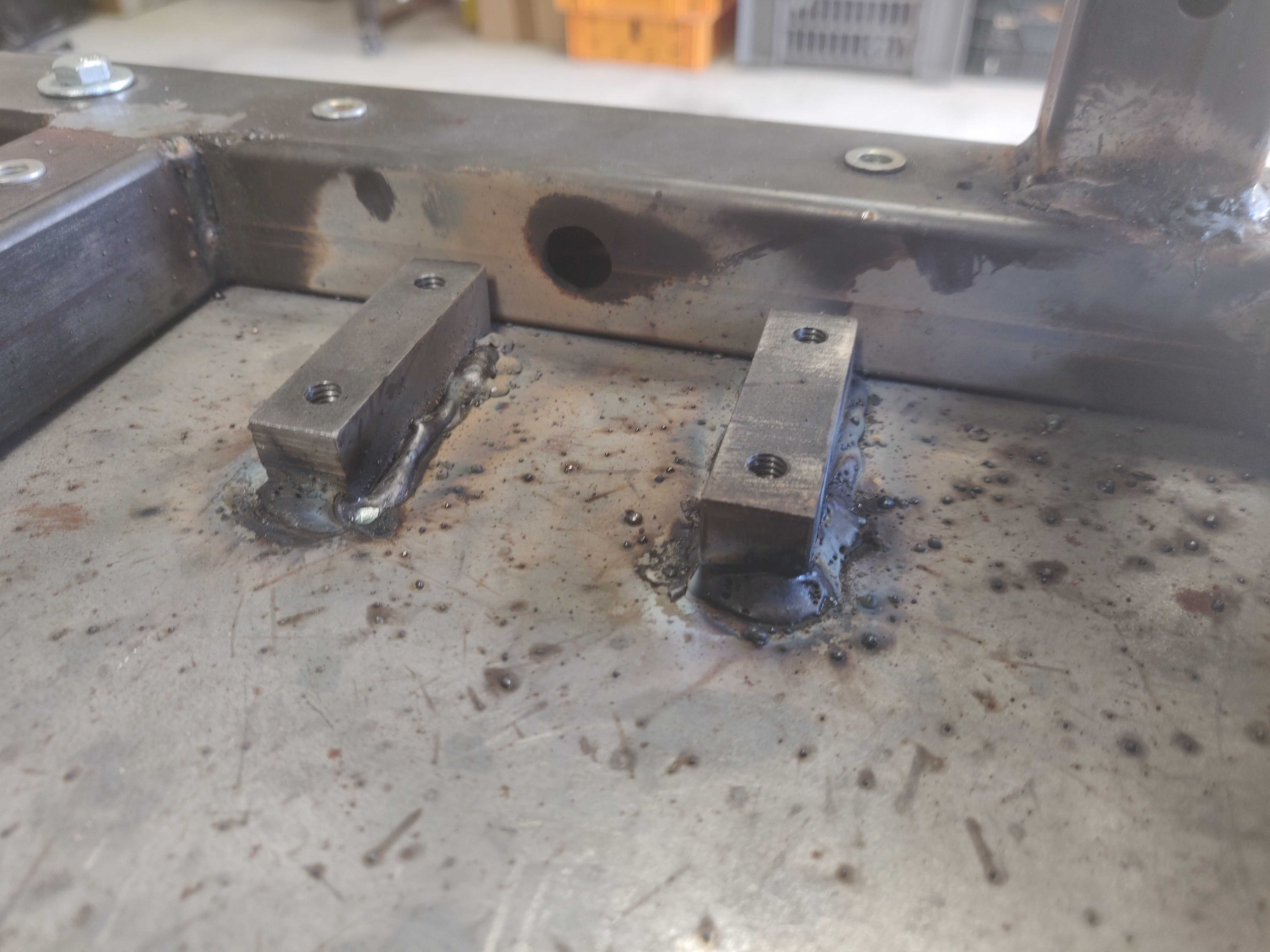
... and the mounts welde to the bottom plate ![]()
I also welded U shaped profils to prevent the plate to bend too much under the torsion strain ![]()
well, welding DOES induce strains from heating... ![]()
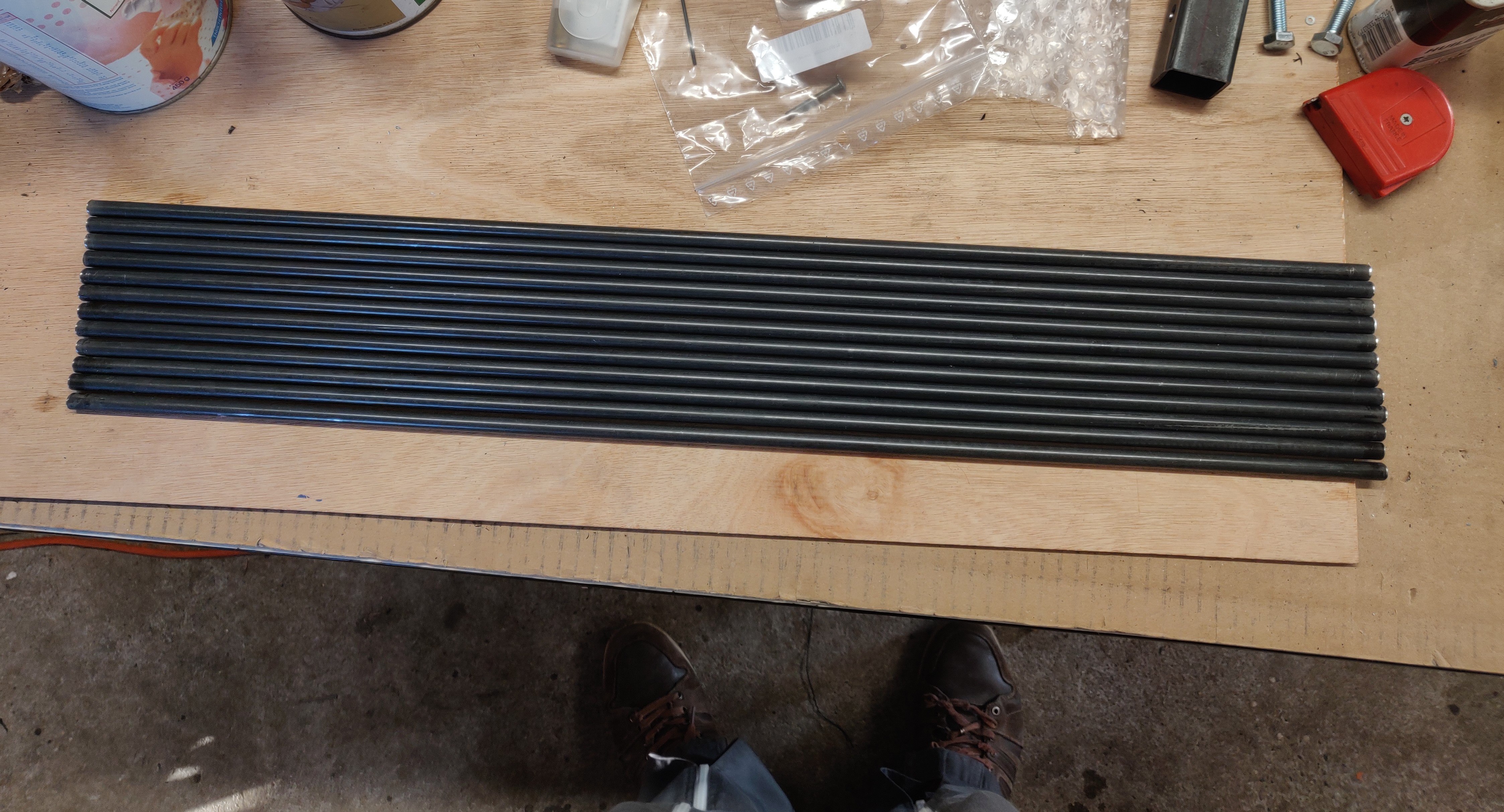
1300MP high strengh spring steel will be used for the torsion bars ![]()
The torsion bar pivots inside bushings -
GEARBOX, Mk2
11/14/2020 at 20:36 • 0 commentsSWITCHING GEAR...
(continued from log "Gearbox Mk1")
Since I was going to face major problems with the Mk1 gearbox, I anticipated the construction of Mk2, featuring :
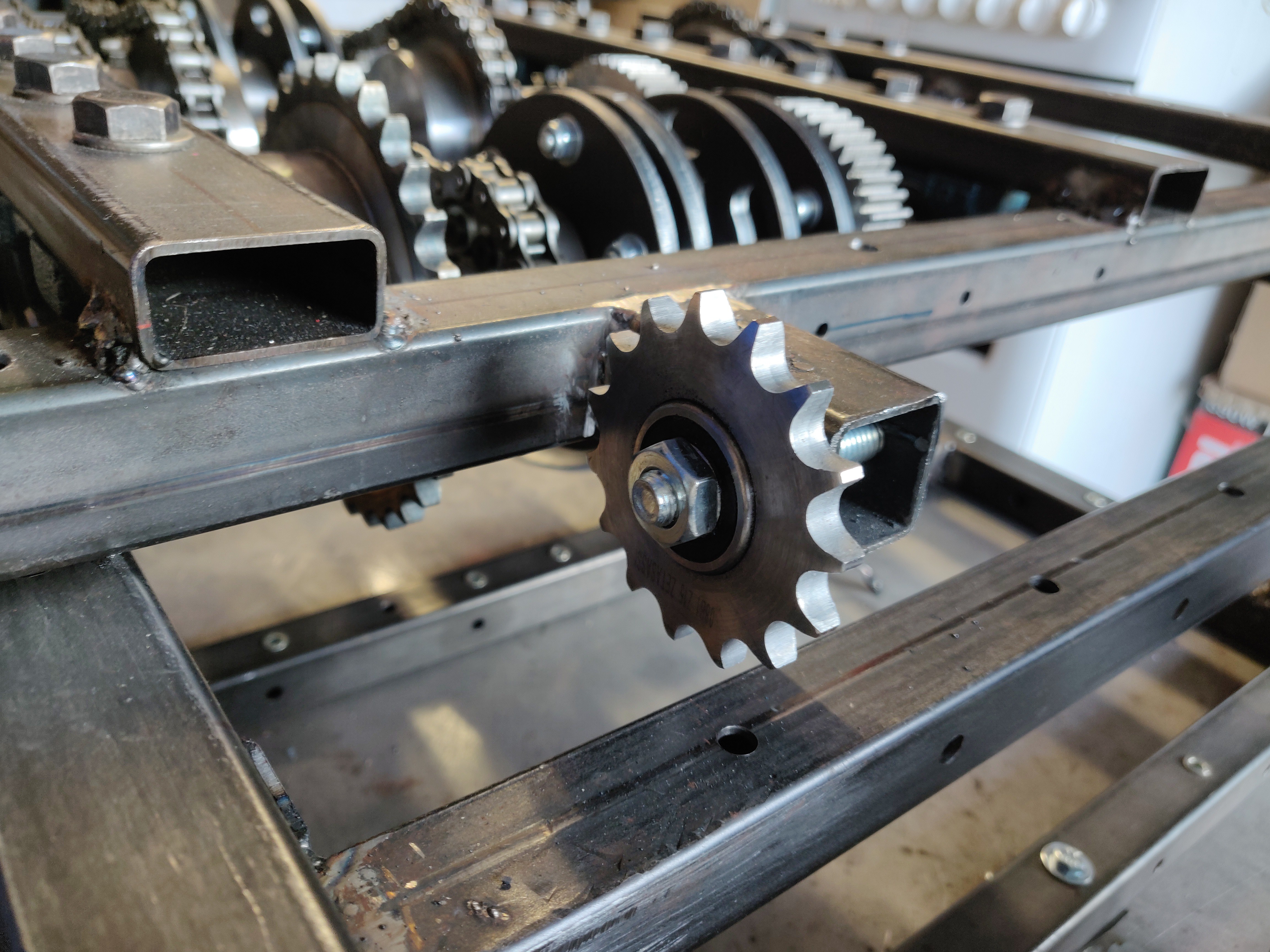
-Sprocket tensioners
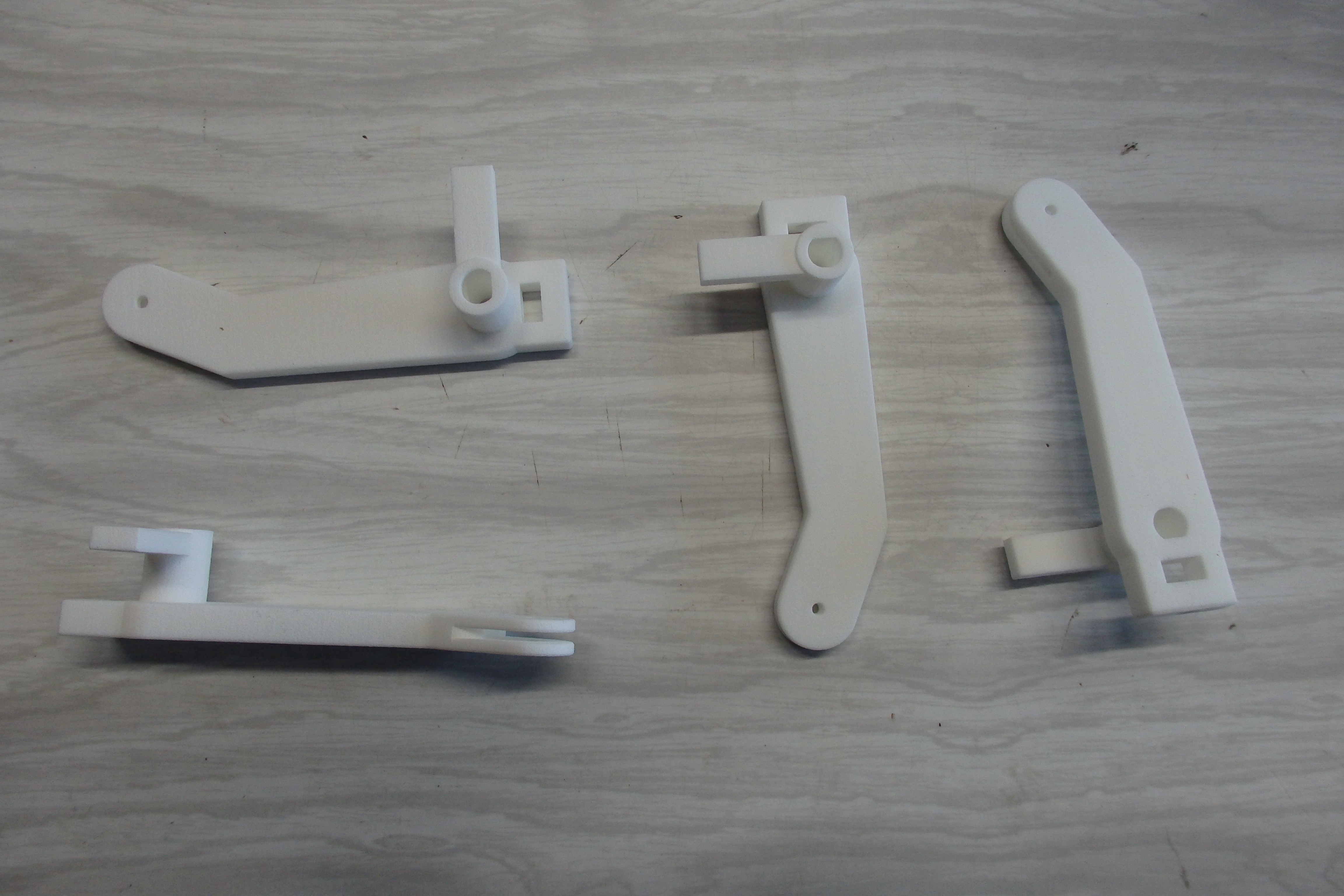
-Full metal shifting forks
-Additional shaft, allowing to dismount the gearbox more easily.
It features 4 reversible gears.
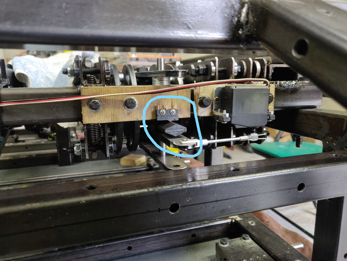
There are no synchronizers, jus basic dog clutches. The dog clutches are motioned by 9kg RC servos, from an arduino.
It is a semi-automated gearbox : when pushing "shift up" or "shift down", the algorithm does all the necessary steps to change gear.
It is a semi-intelligent gearbox that detects when errors occure (e.g. blocked mechanism) and acts accordingly.
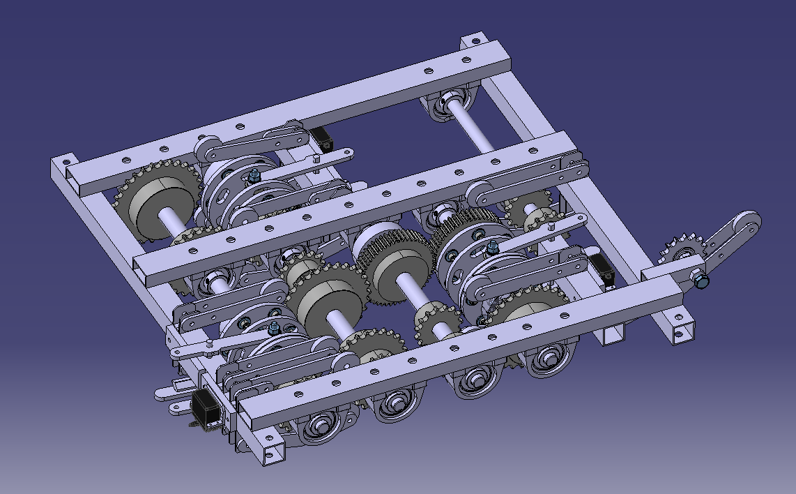
The first trial turned to be pretty succesful and quite promissing :
![]()
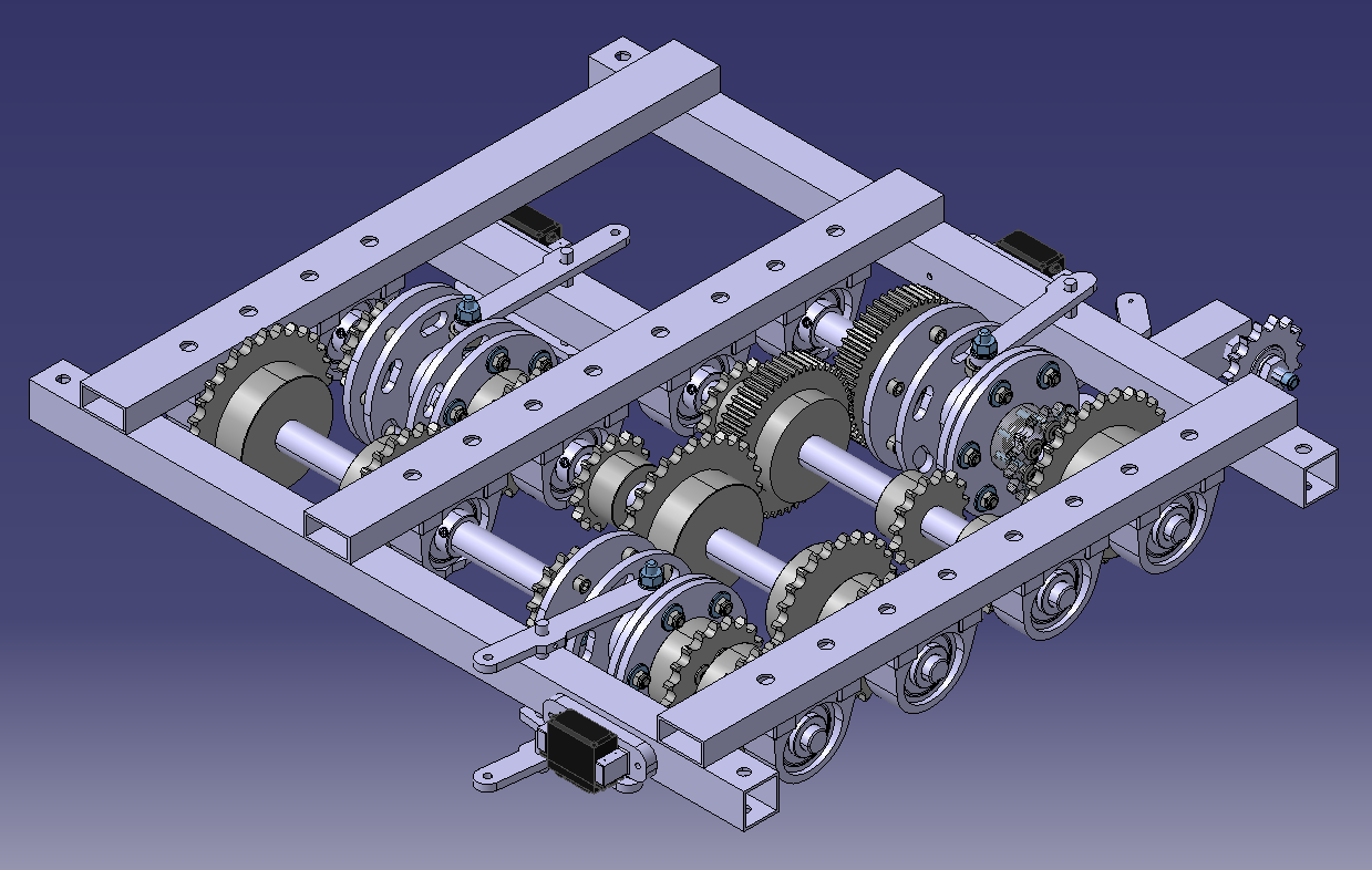
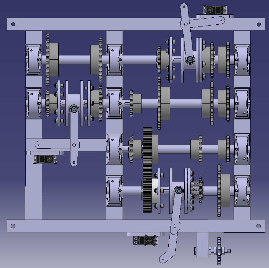
From CAD.... ![]()
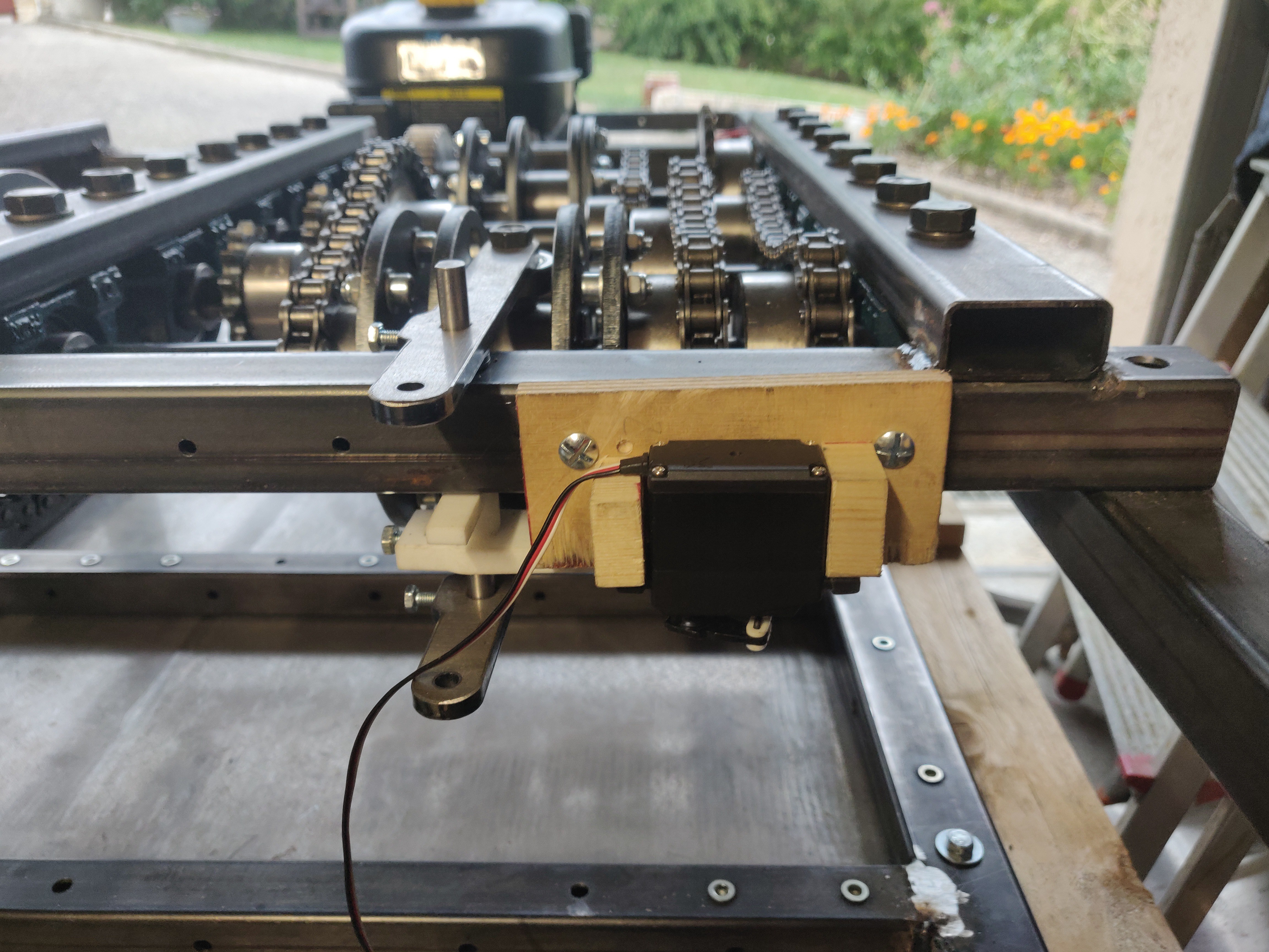
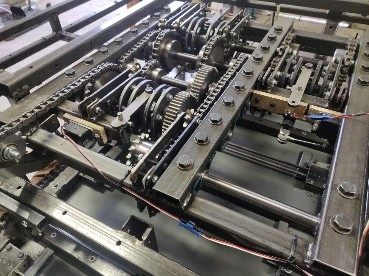
... to reality
![]()
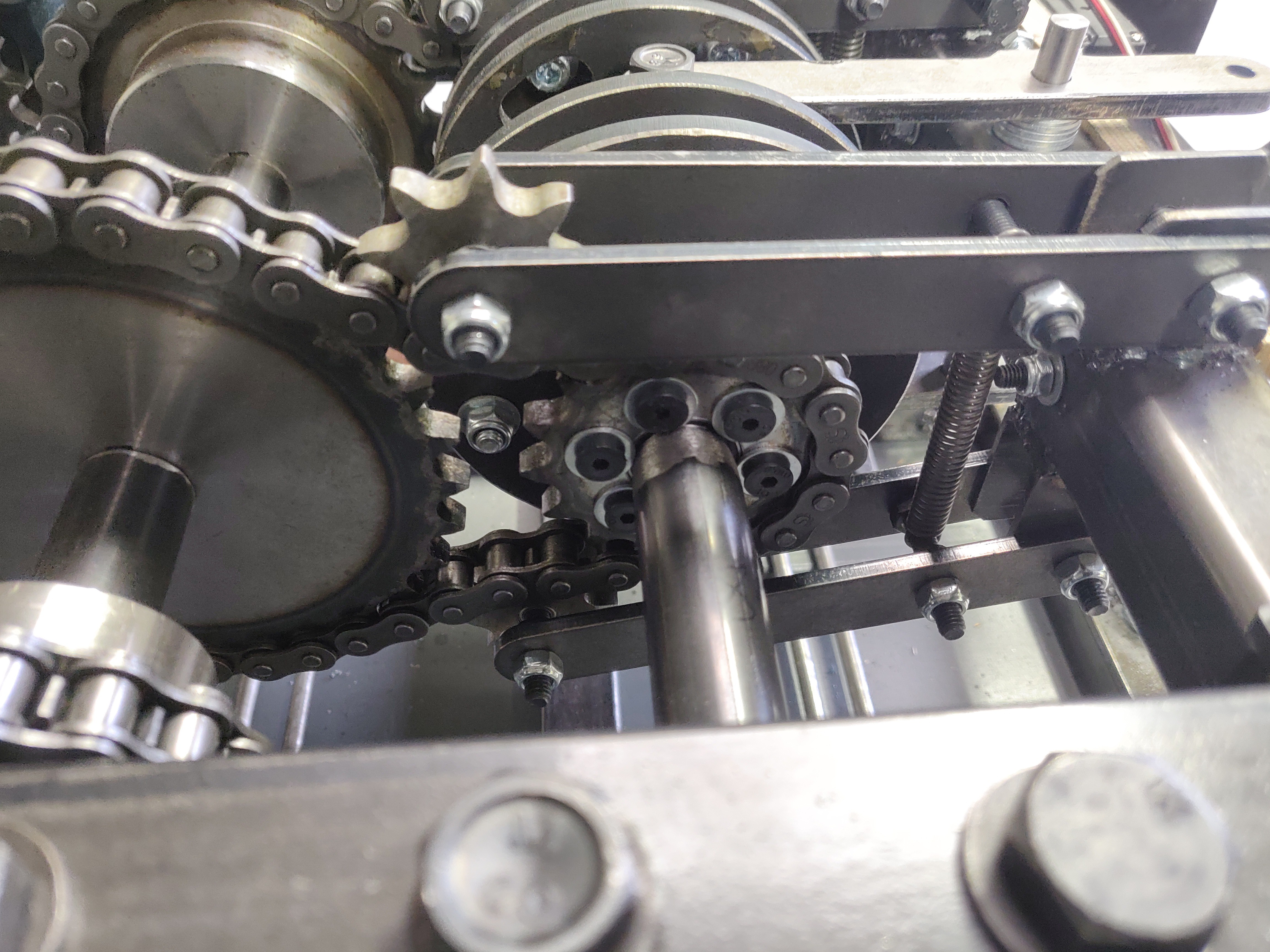
Tensioners ![]()
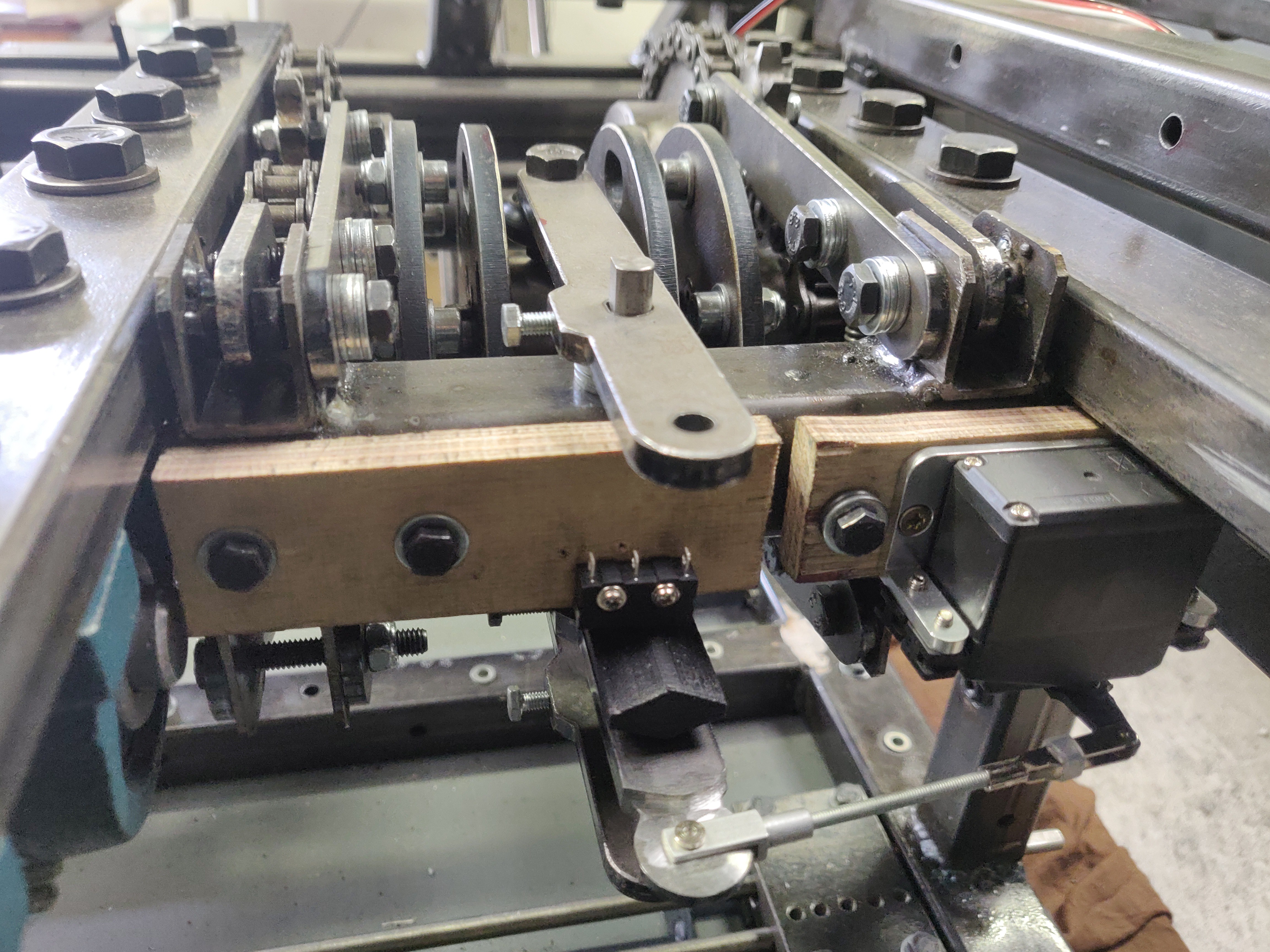
New metal forks ![]()
Switch detecting dog clutch position Cfqdfdqfgf
![]()
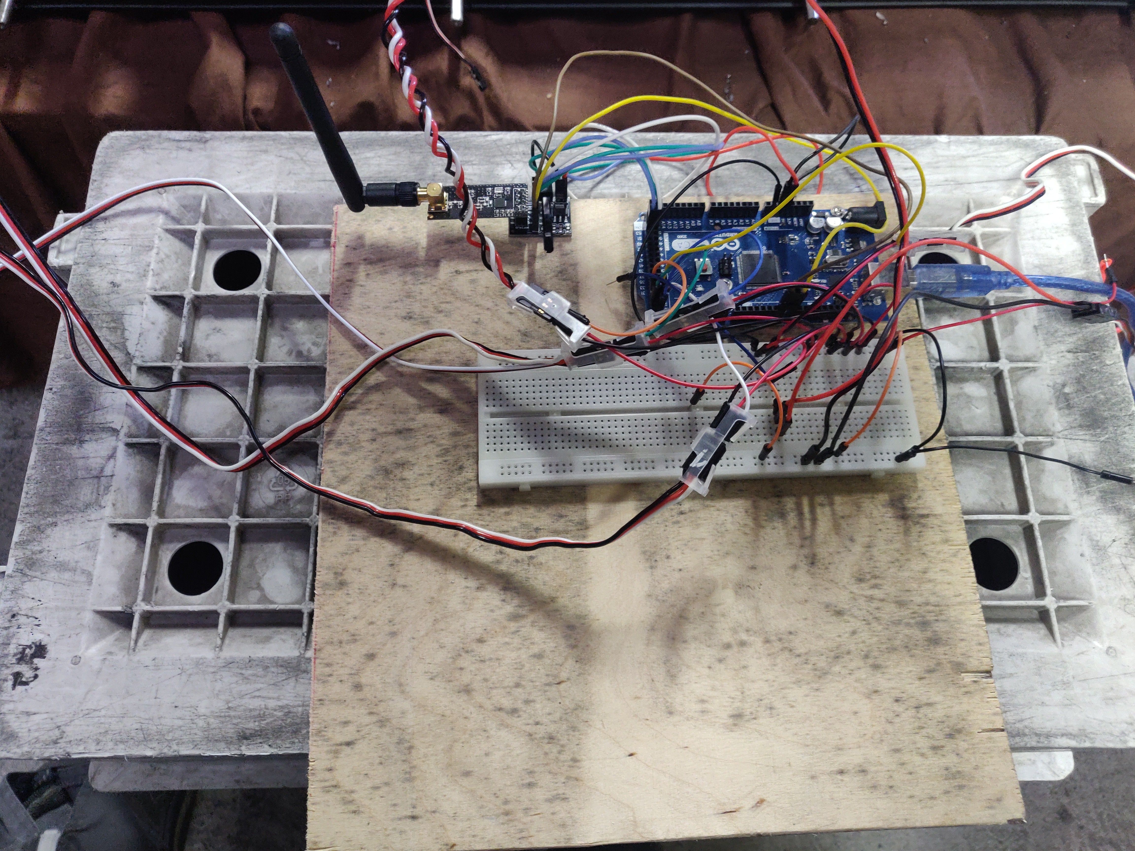
Arduino + radio module
![]()
CONCLUSION
The concept proves working pretty well (including at high speed) without load.
We'll have to test it again with the rest of the transmission, (double differential + steering system) ; under load once the chassis is done ; and under full load once the turret is complete... -
RADIO
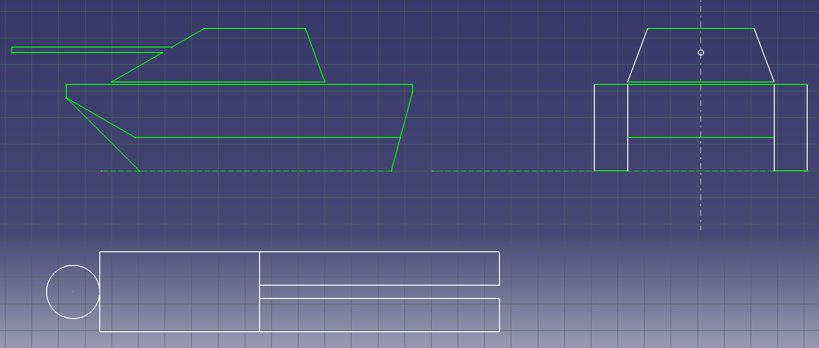
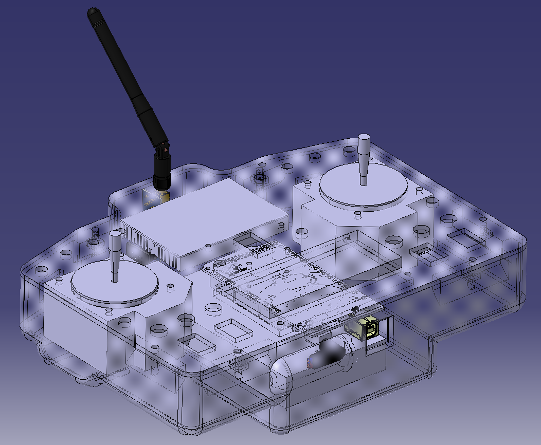
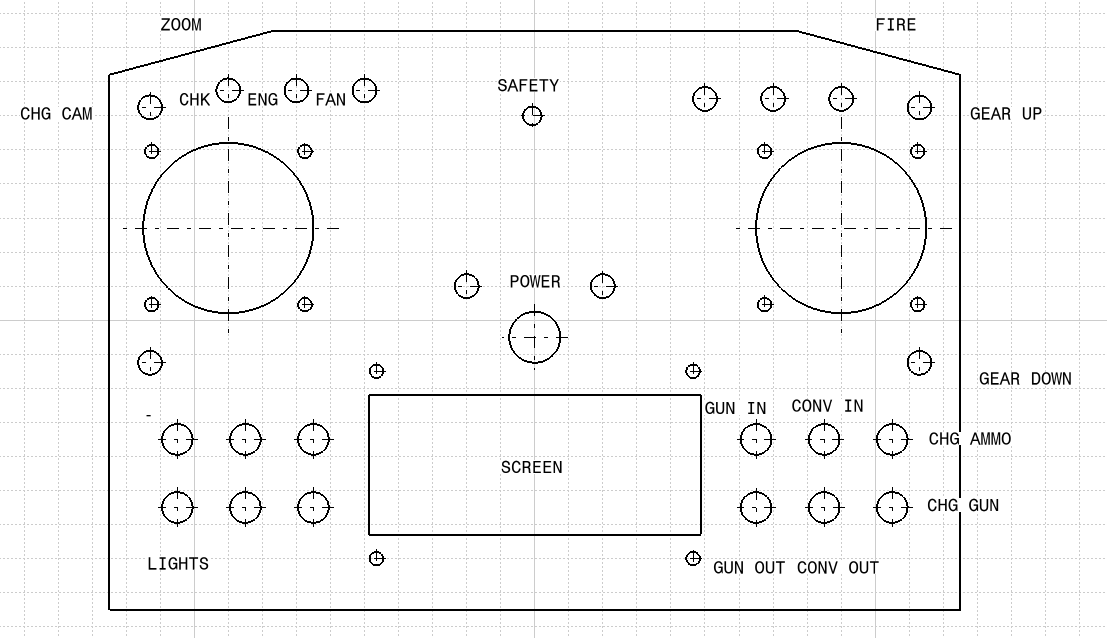
05/17/2020 at 07:52 • 0 commentsALL WE HEAR IS RADIO GAGA
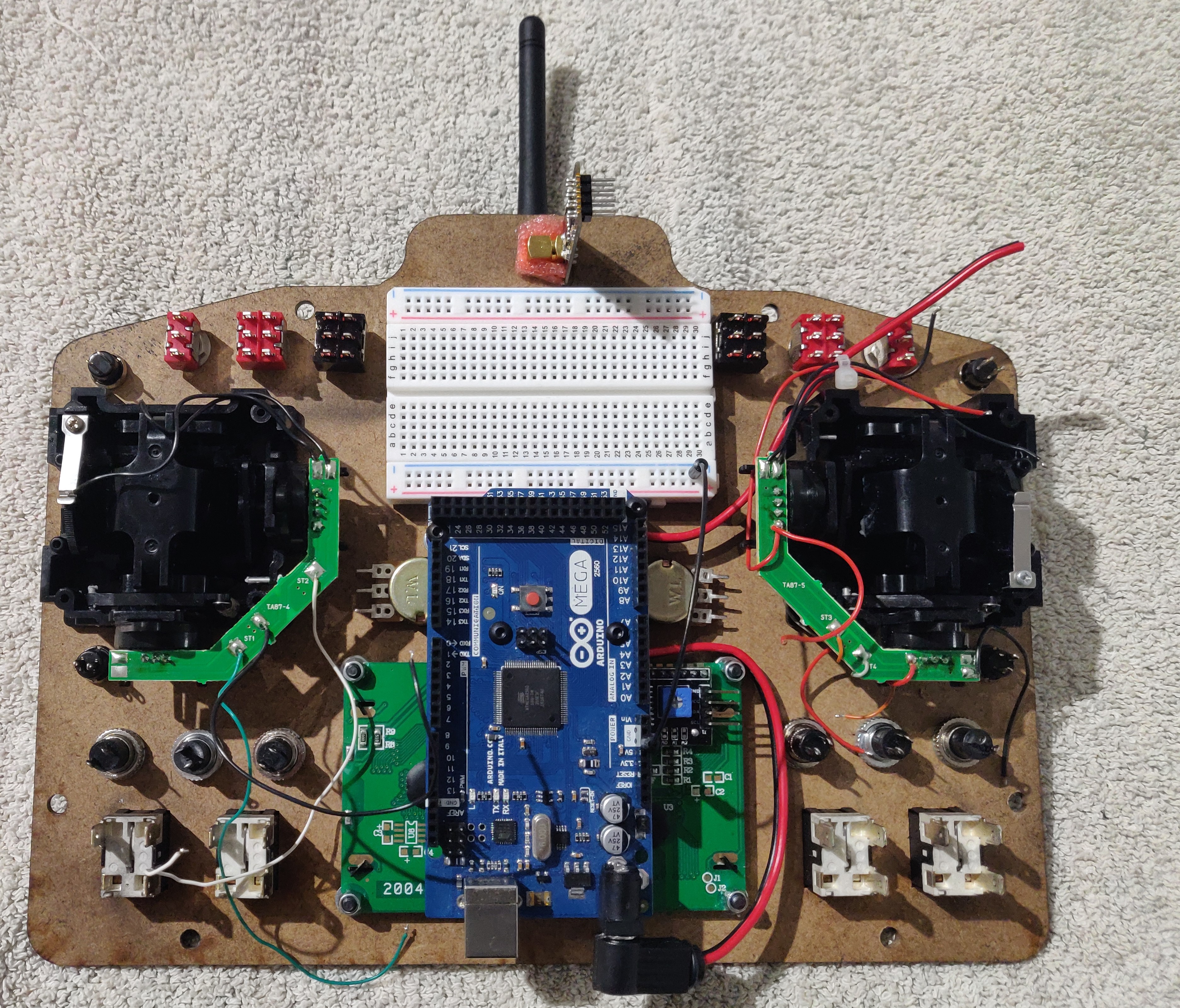
Since I didnt really learn electronics at school, I expectef the radio to be quite difficult to build. but it turned out easier than I thought, it's just a basic button box, with an Adruino, a screen, a 2.4GHz module and a battery of course. The box is 3D printed (SLA) and the pannel is made out of wod, laser cut.
![]()
![]()
![]()
![]()
![]()
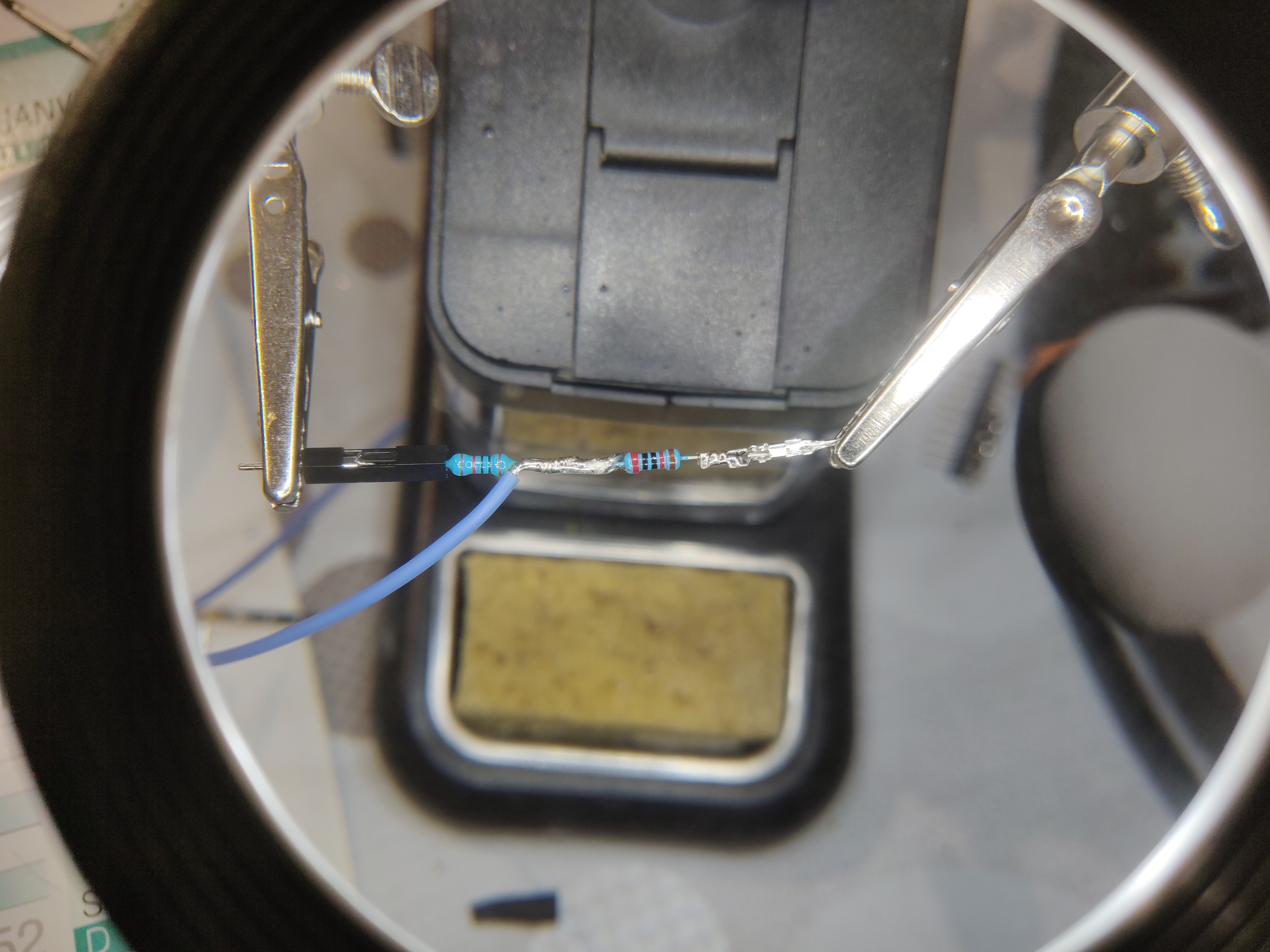
HOMEMADE BRIDGE DIVIDER![]()
![]()
-
CHASSIS FRAME
05/16/2020 at 19:18 • 0 commentsGETTING THE RIGHT FRAME OF MIND
SUMMARY
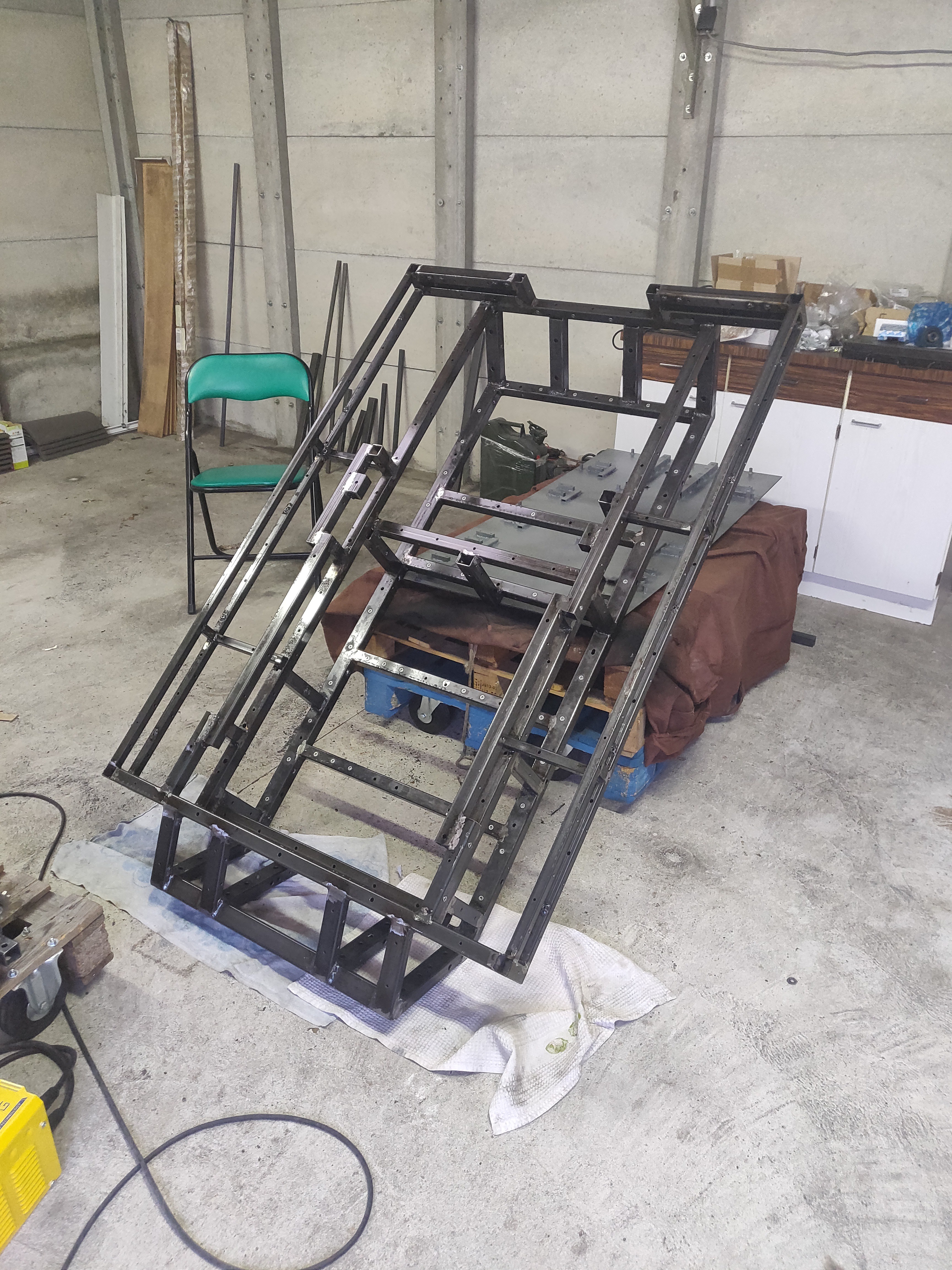
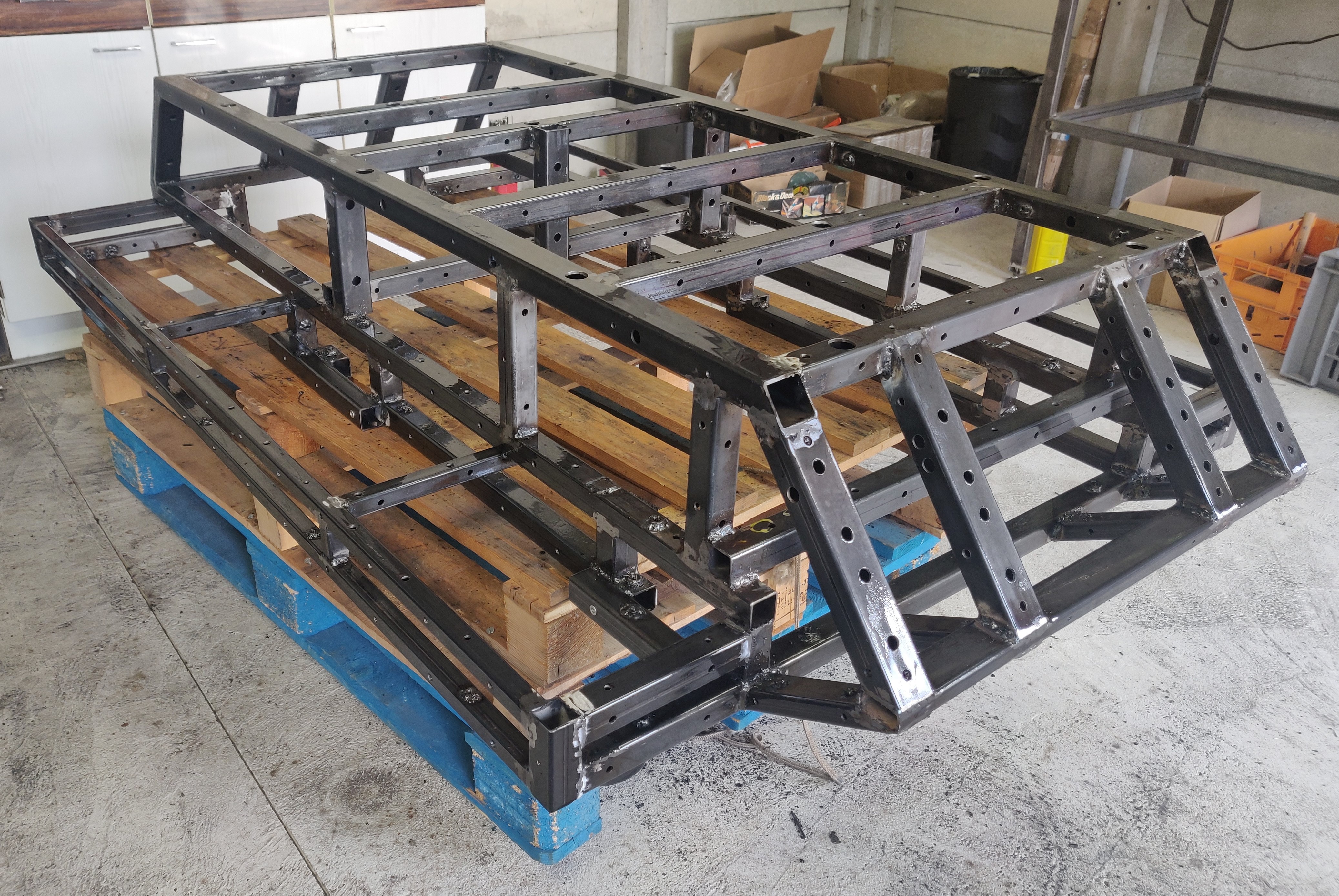
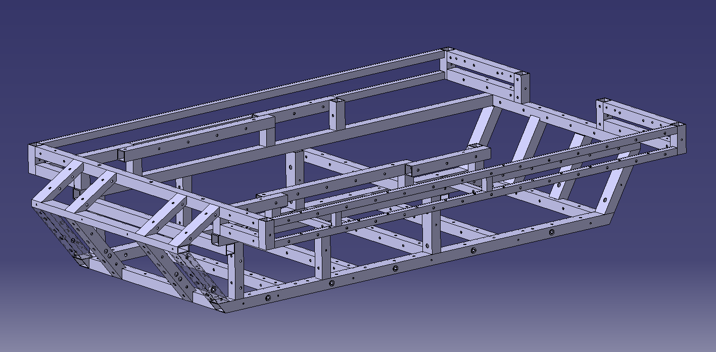
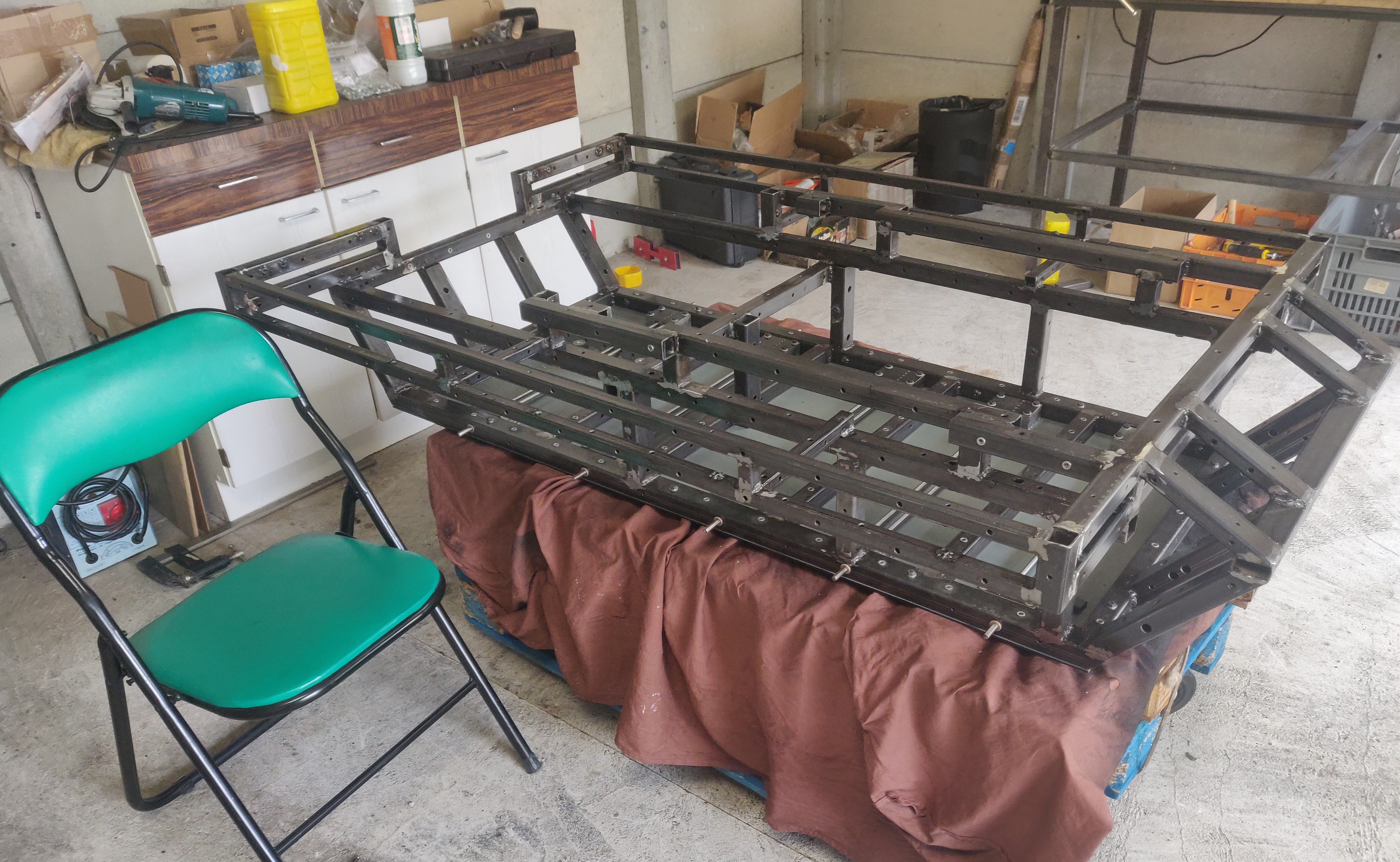
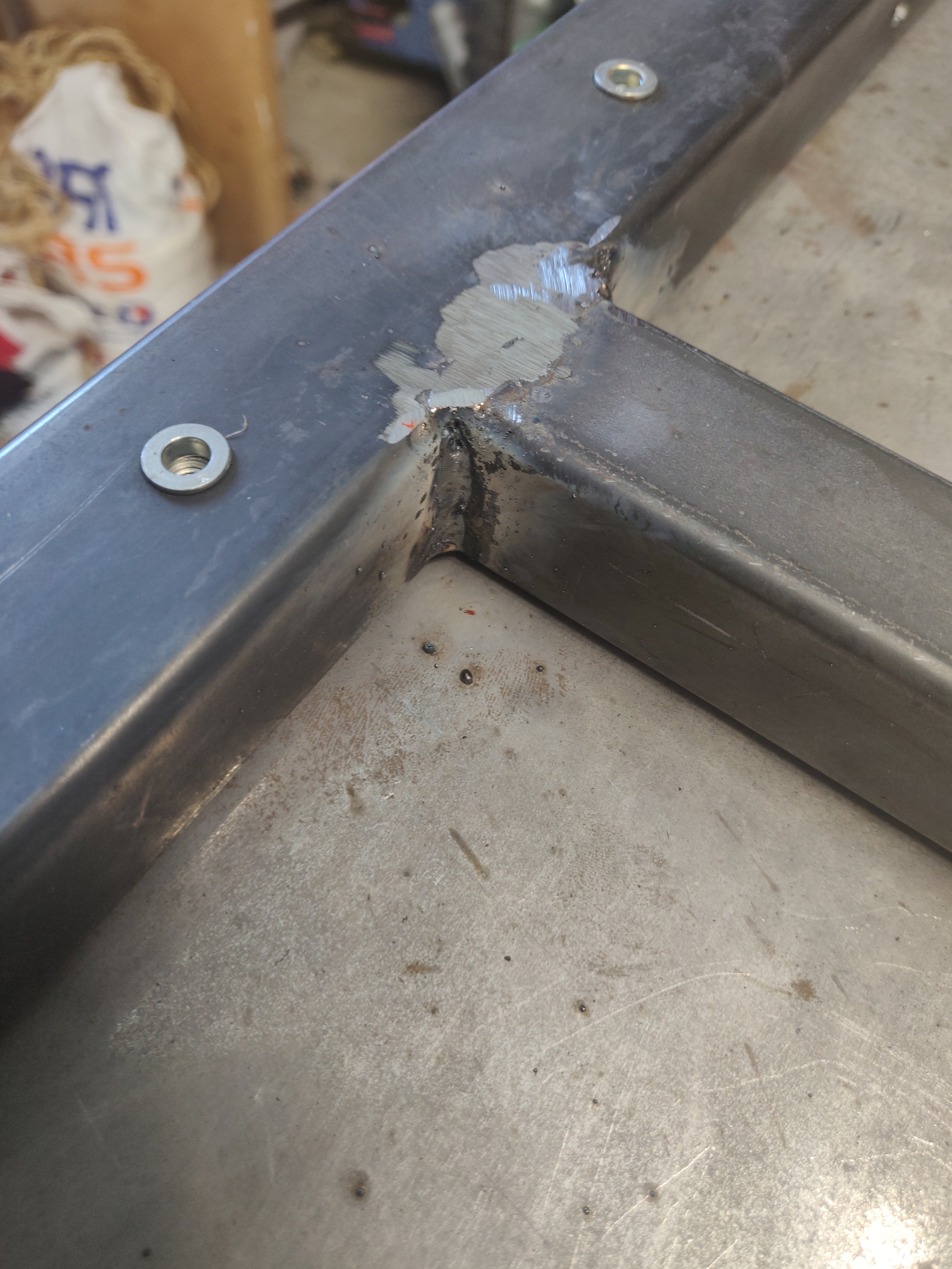
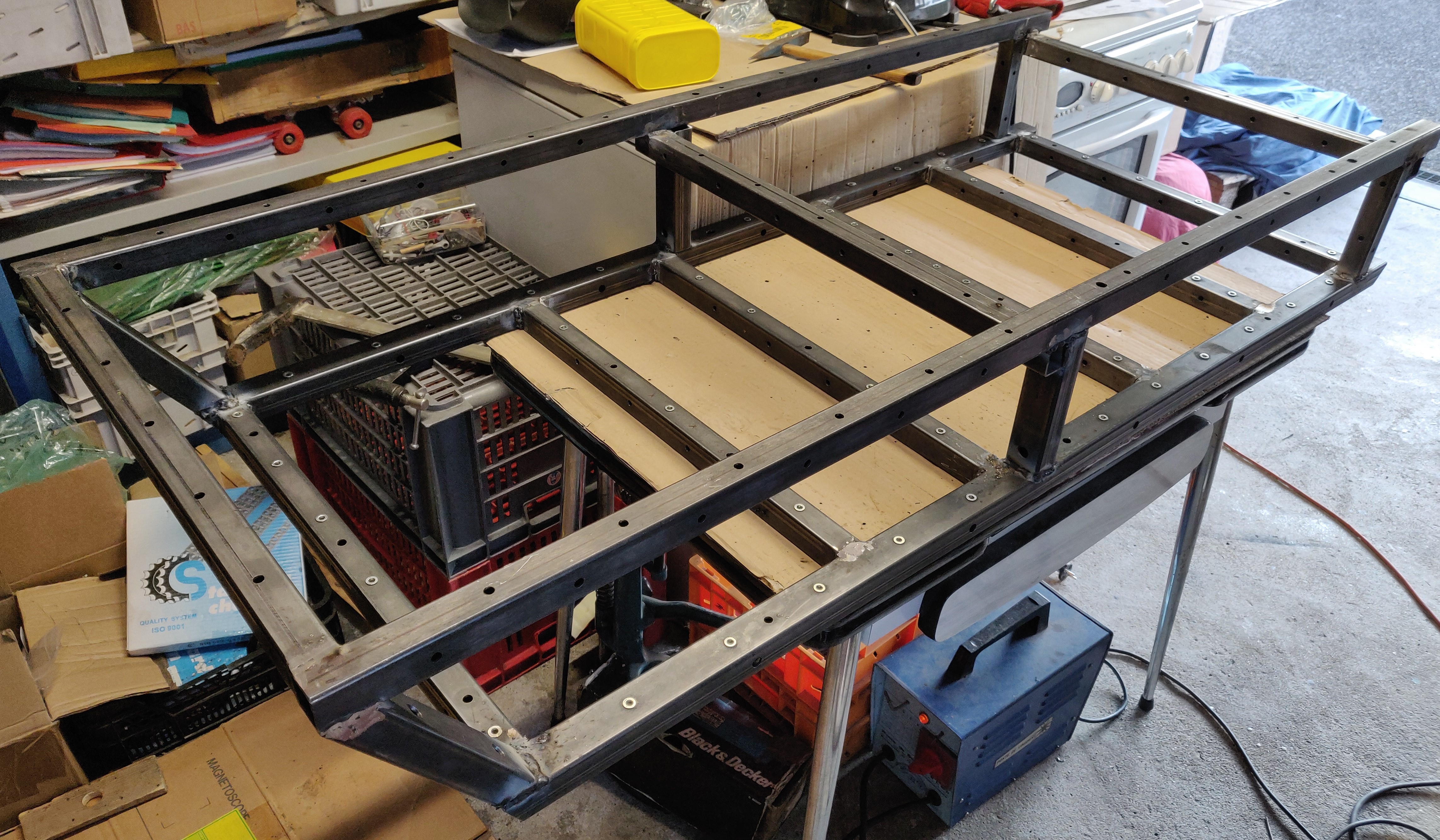
Building the frame wasn't that hard, but much, much longer than I expected. I had to drill several hundreds of holes. I also had to be very patient and very cautious with positioning and maintaining the profils while welding. Since I am no professional welder, I had to improve some weldings after the polishing step revealed weaknesses. The most difficult part was to cut and weld the angled profiles properly.
![]()
From CAD... ![]()
... to reality CONSTRUCTION
![]()
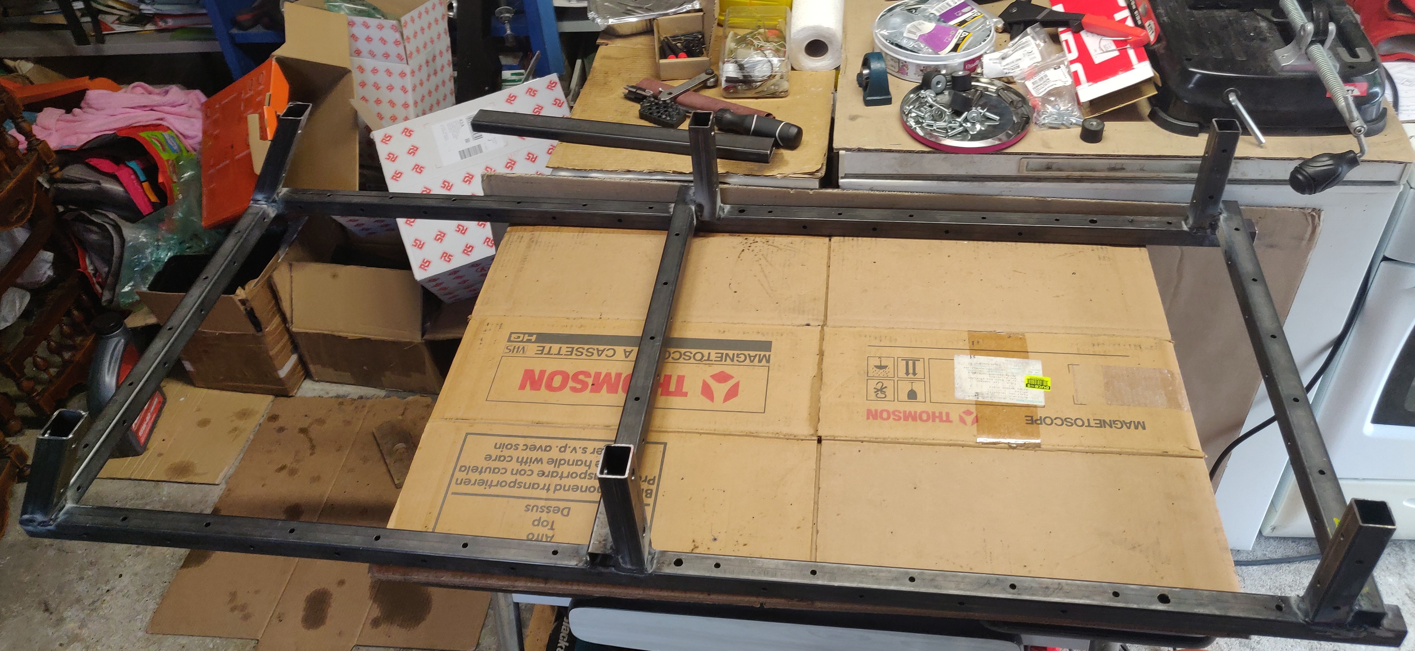
At first I made the frame in 2 parts : top and bottom
And it was a bad idea :![]()
![]()
MUCH BETTER ! ![]()
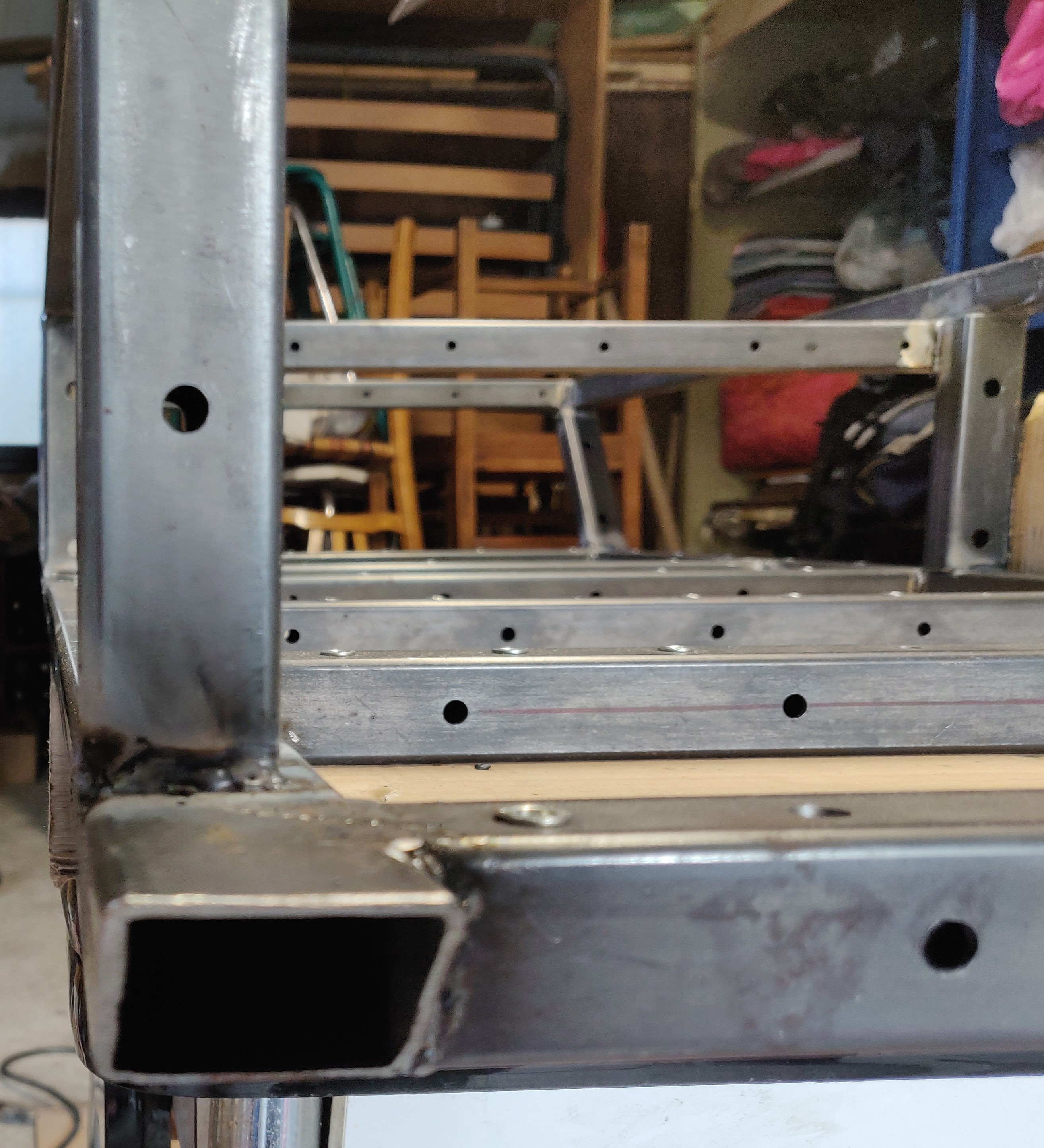
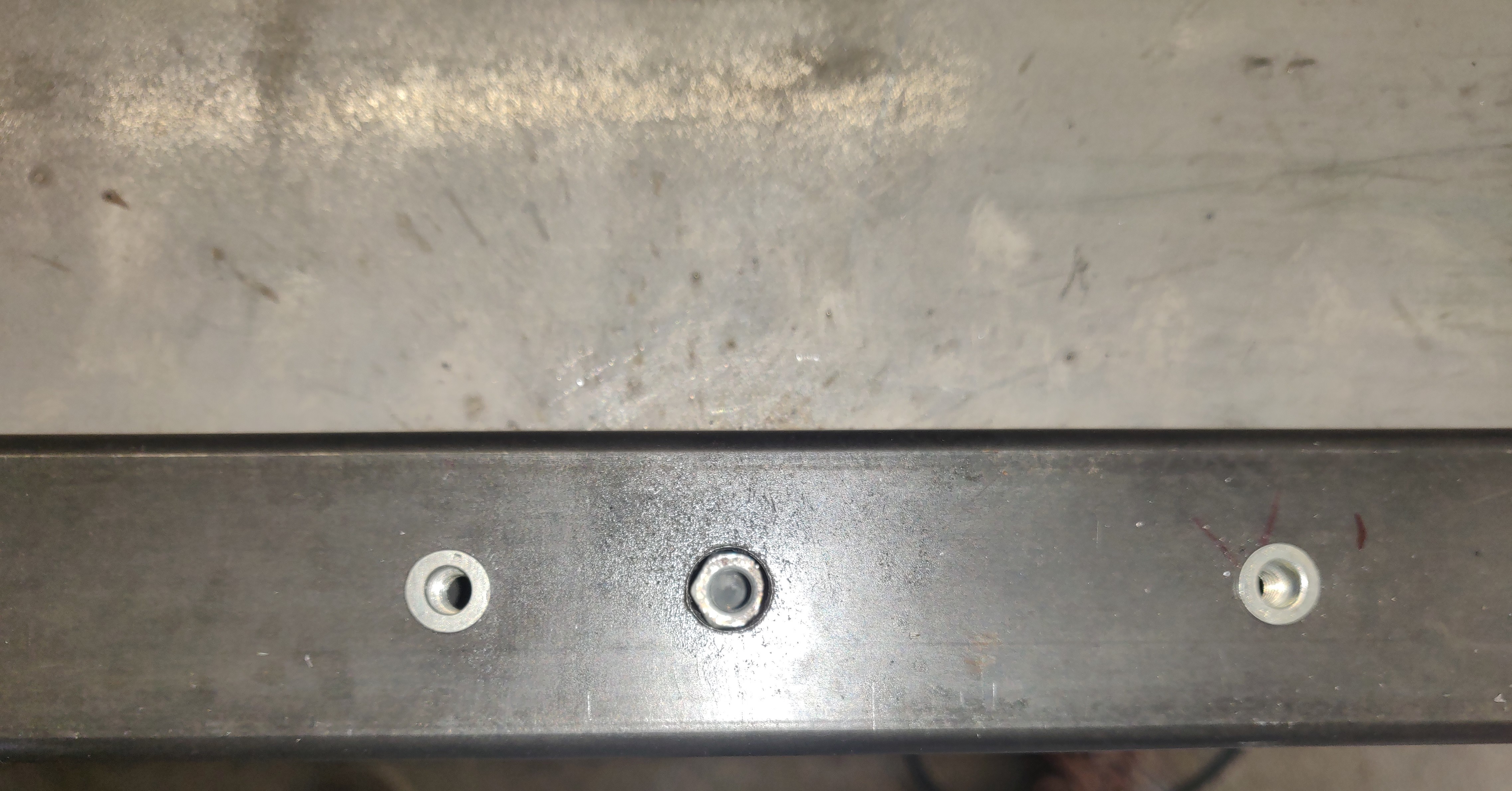
profil welding. I also Riveted a lot of nuts for potential mountings interfaces ![]()
![]()
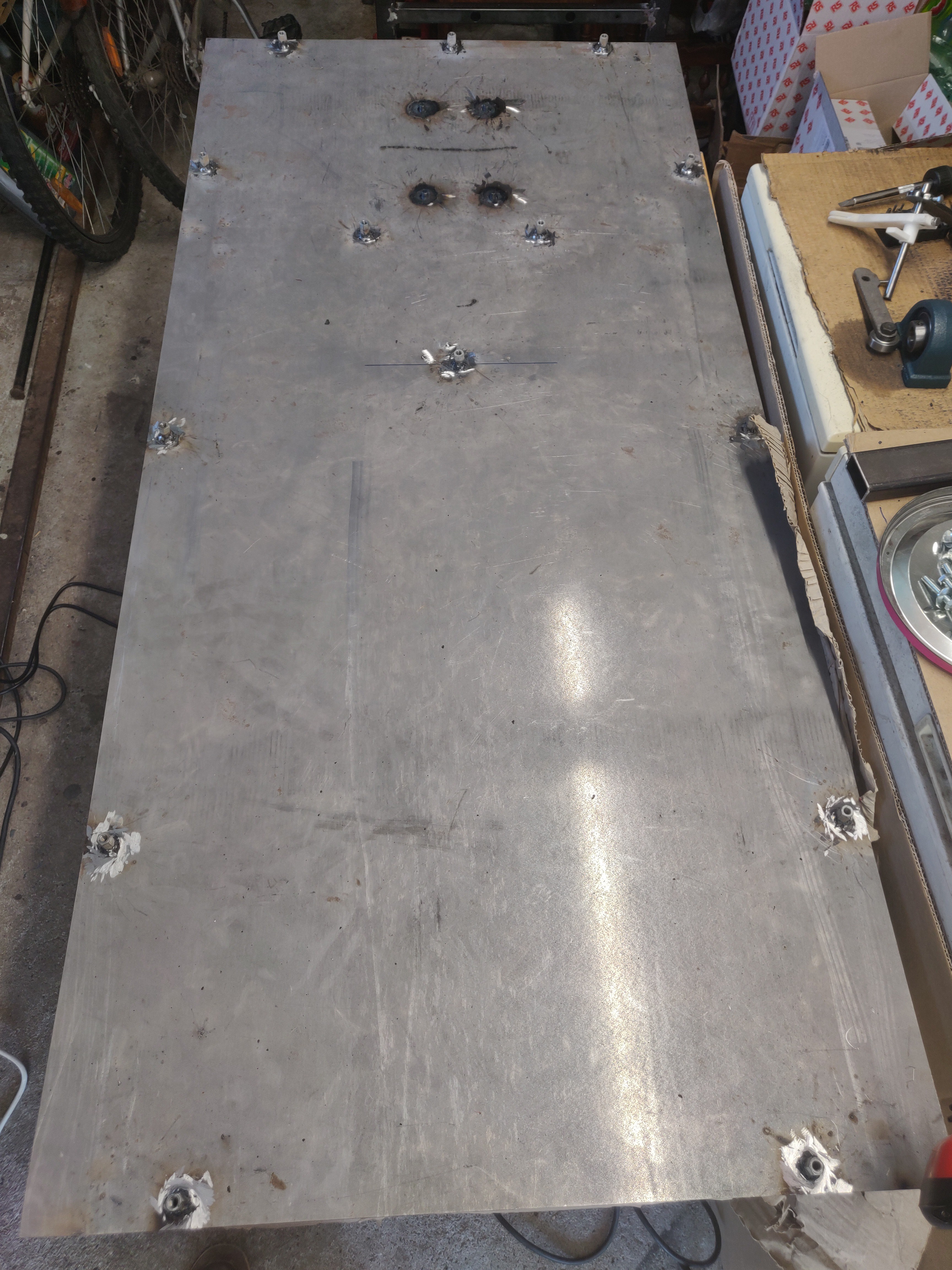
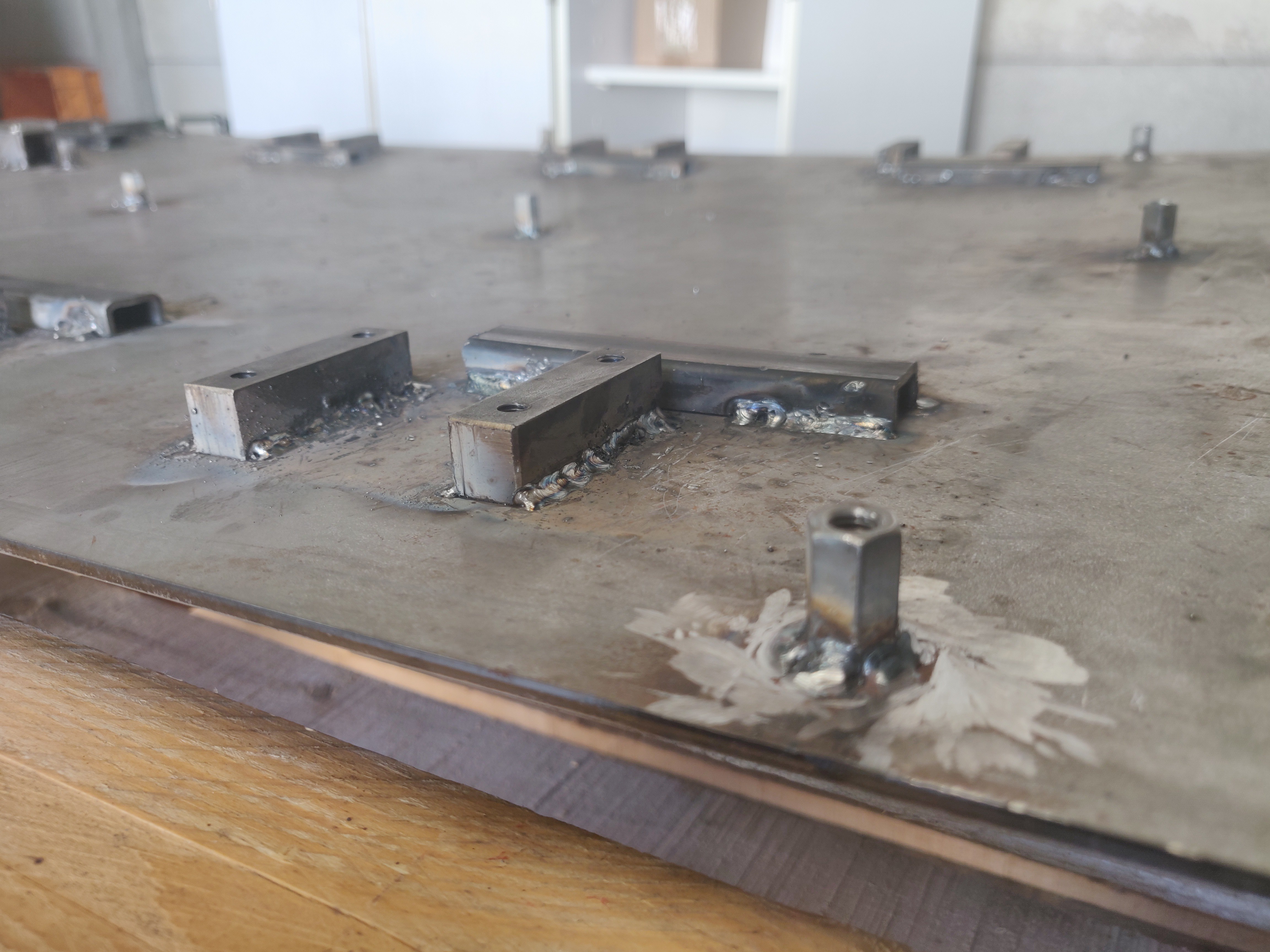
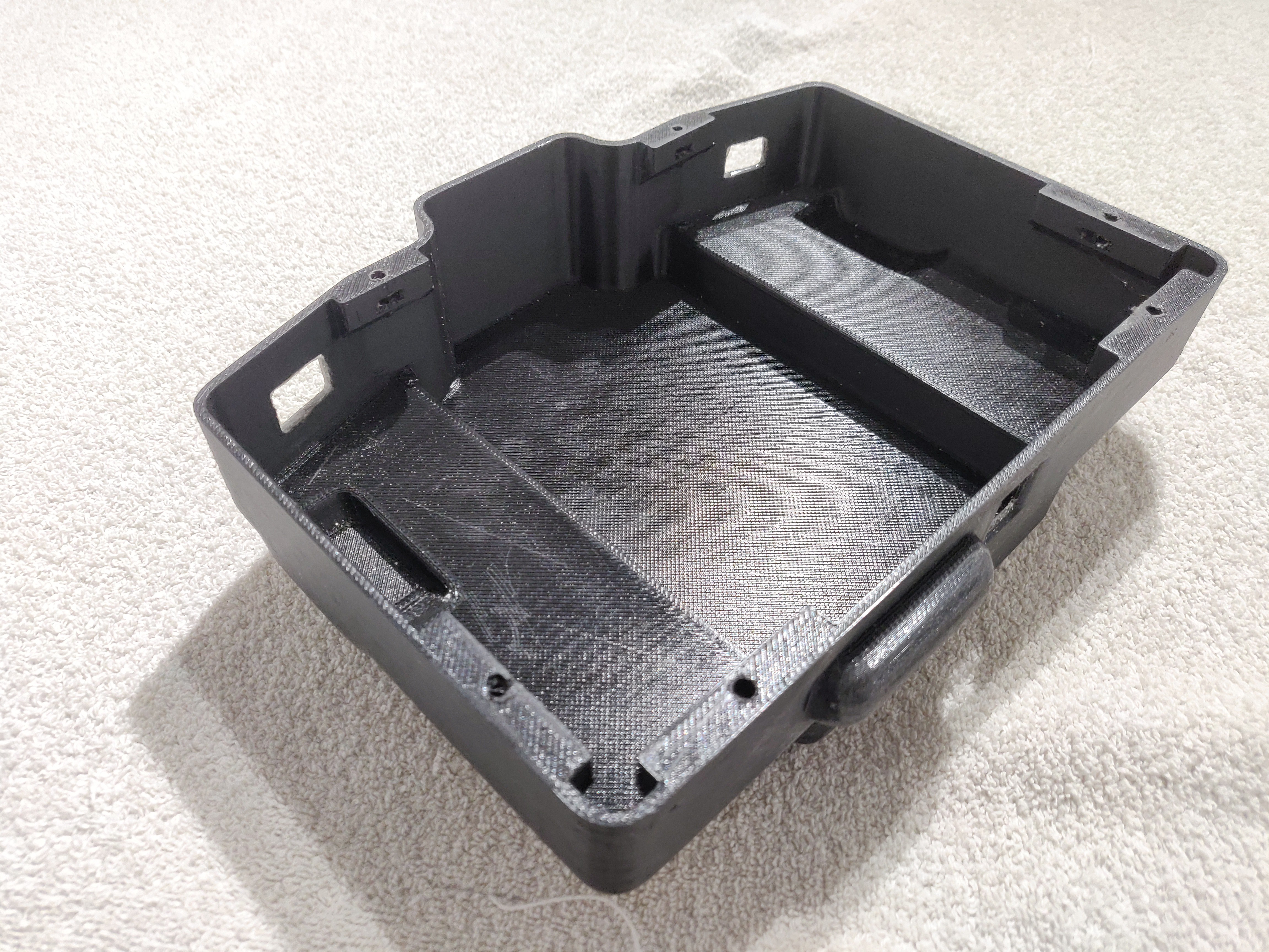
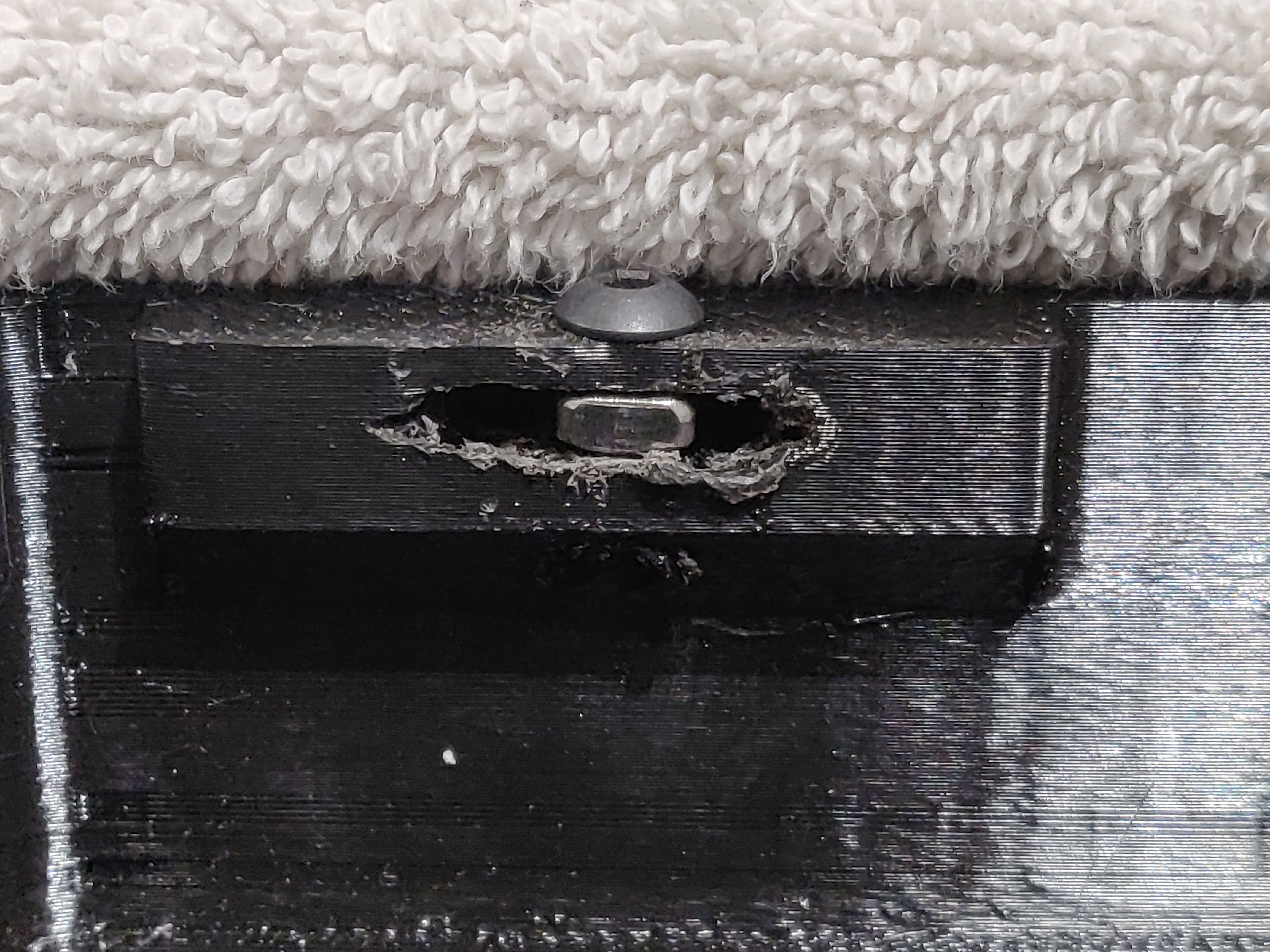
The bottom plate will be fixed to the chassis by these nuts ![]()
Here we see the plate's nut inside the frame's hole ![]() welding of the screws for engine mounts
welding of the screws for engine mounts![]()
Bottom plate ![]()
Core of the frame assembled with gearbox Mk1, and engine... So far so good! ![]()
Still got a lot of work... 
These front sections were very long to cut and assemble, because of the tricky angles 
Front view
Then i welded the left and right wings + turret mounting + rear section :![]()
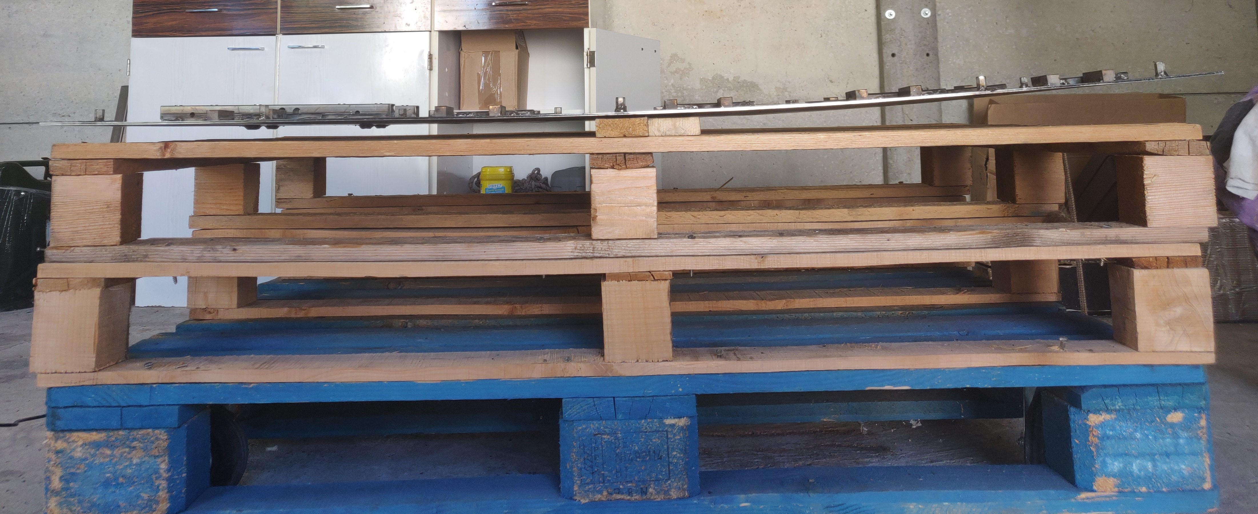
the pallets are 1m20*0.8m After a few improvements on the fly, the frame is now complete. I then added a rust protection coating on every single surfaces. Just like real tanks, this one will have a long, and rough life. Let's protect it from the start.
![]()
Upside down view -
GEARBOX, Mk1
05/16/2020 at 17:20 • 0 commentsFULL SPEED AHEAD !
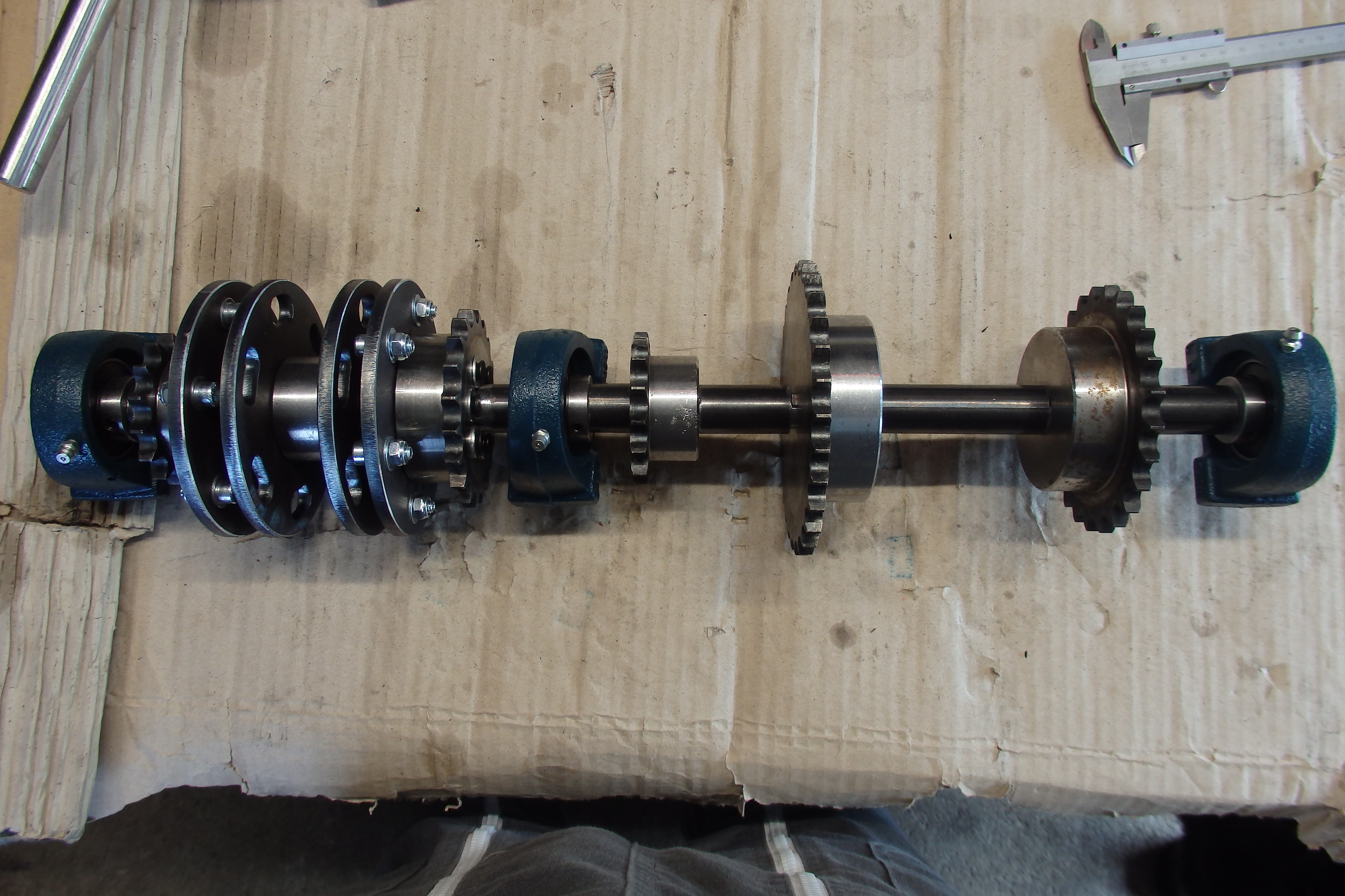
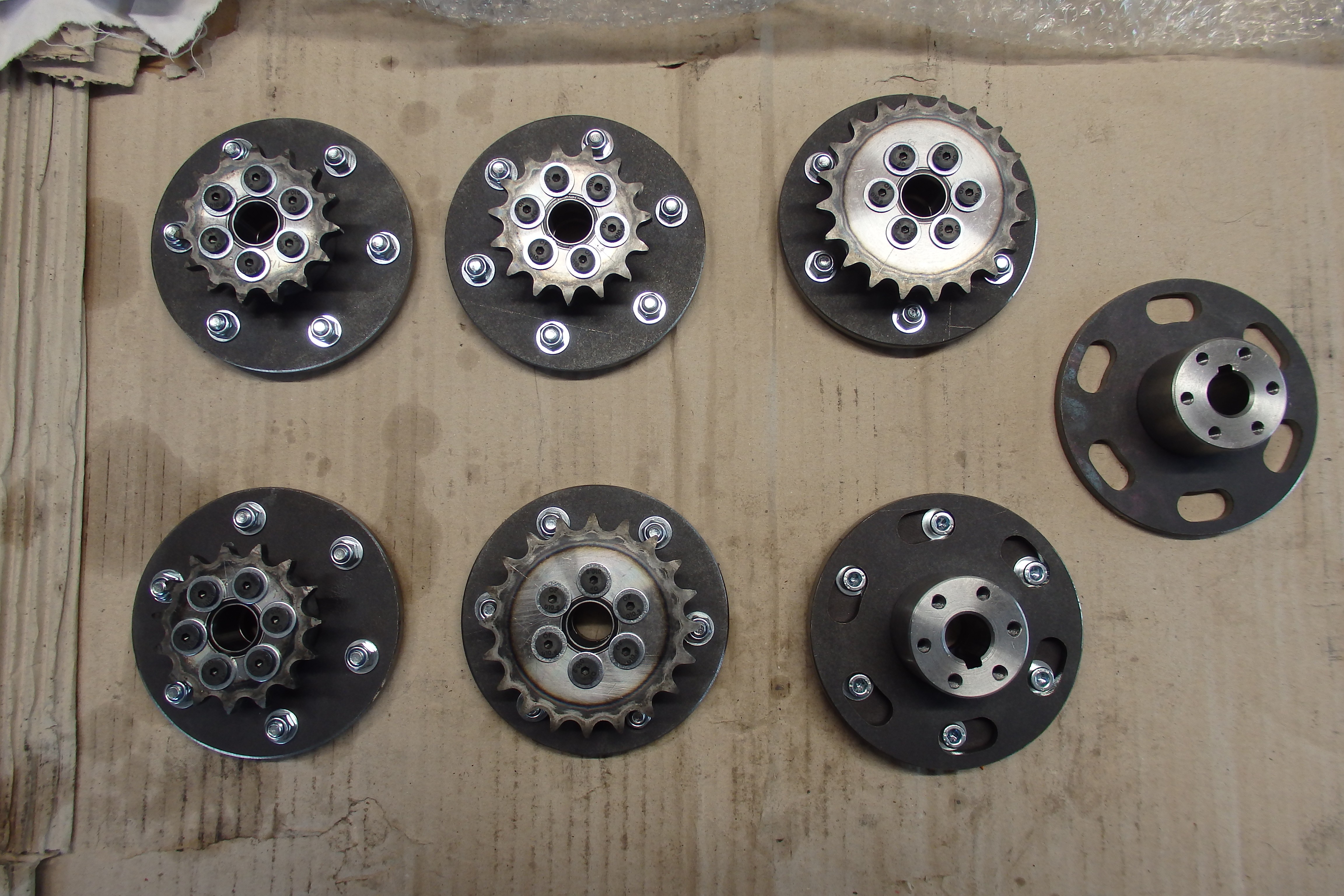
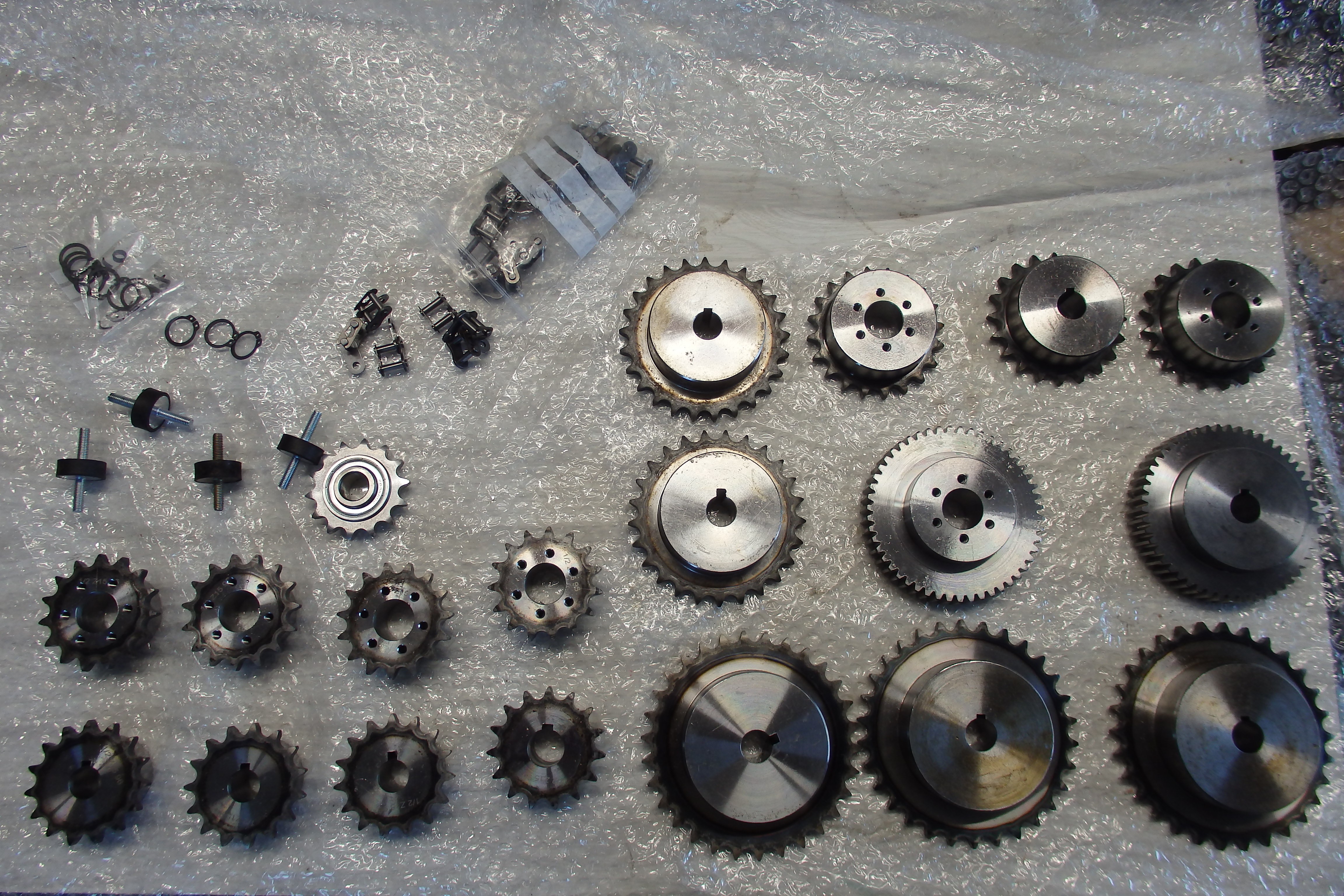
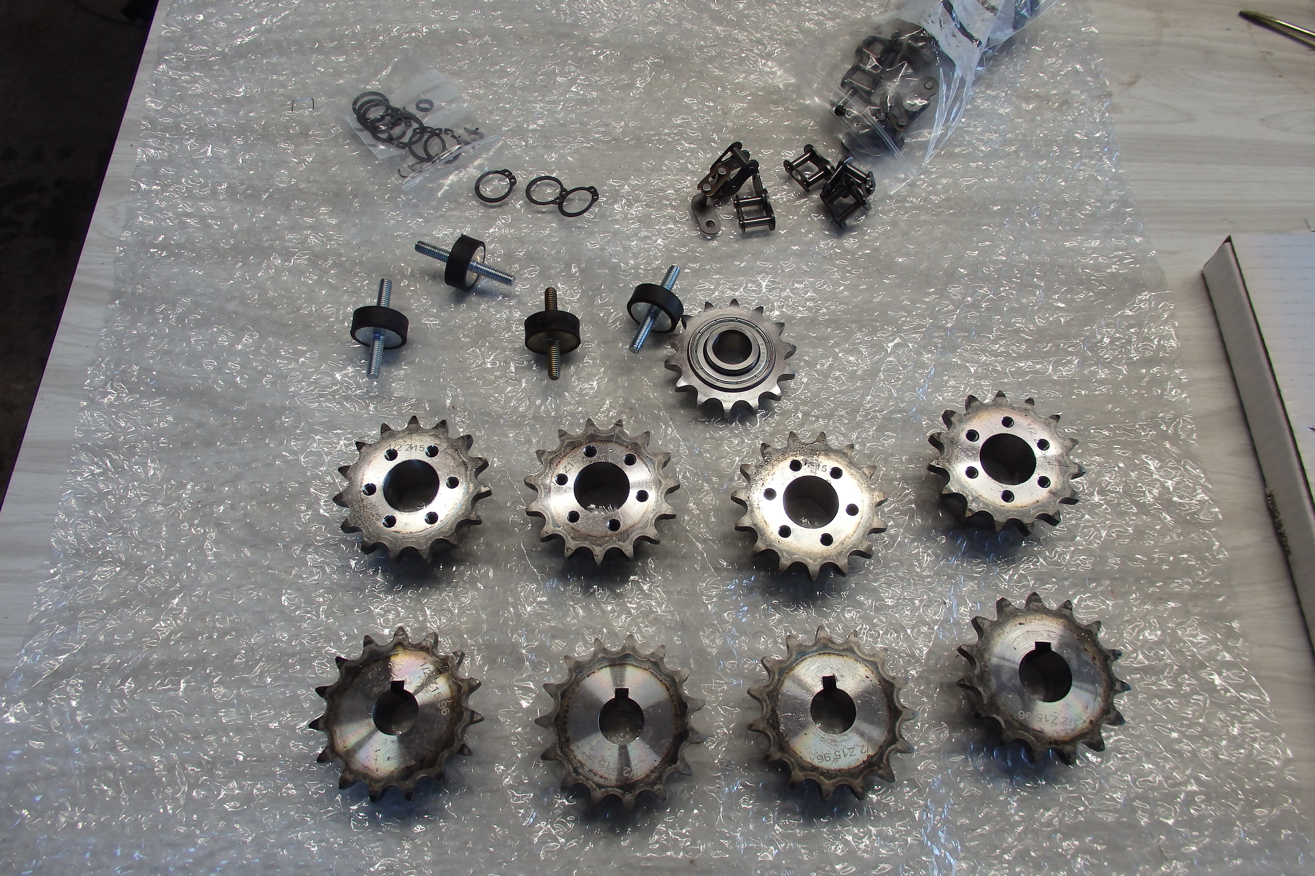
The gearbox design has been quite a challenge : I have a lot of mechanical power to transmit (4.8kW) with a high speed on one side and high torque on the other. Not to mention that the gearbox had to be as compact as possible to fit in the tank. I used roller chains instead of gears to make it easier to assemble run and maintain, as is it my first gearbox project.
![]()
![]()
![]()
![]()
![]()
![]()
![]()
![]()
![]()
![]()
![]()
![]()
CAD![]()
![]()
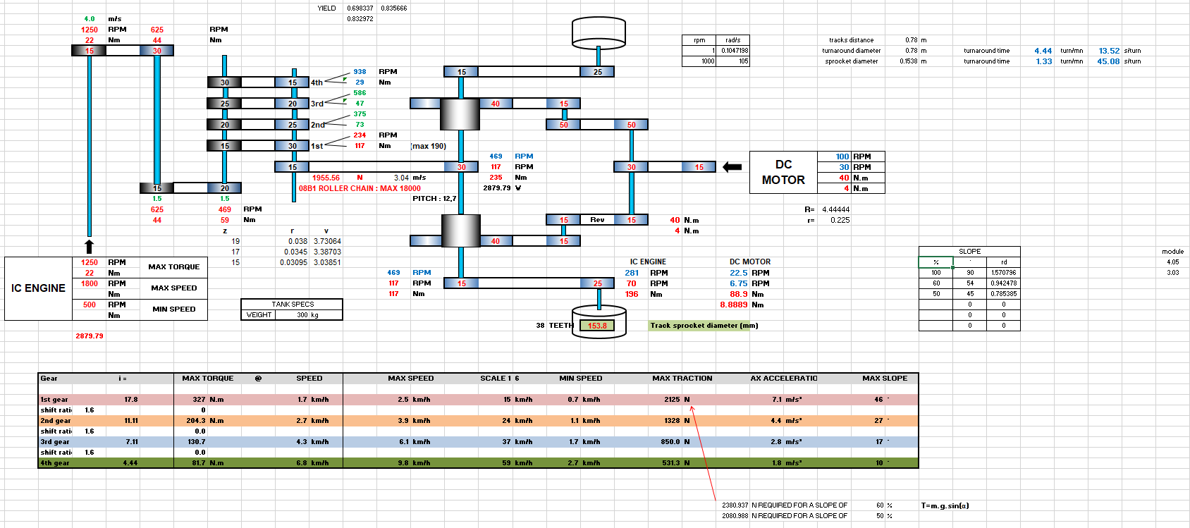
MATH TIME
![]()
OUTCOME
The Mk1 Gearbox has never been tested. I figured I would obviously run to dangerous problems without tensioner sprockets. It would also to be difficult in maintainance to disconnect the gearbox output from the rest of transmission.
See you at the "Gearbox Mk2" post ;) !!
-
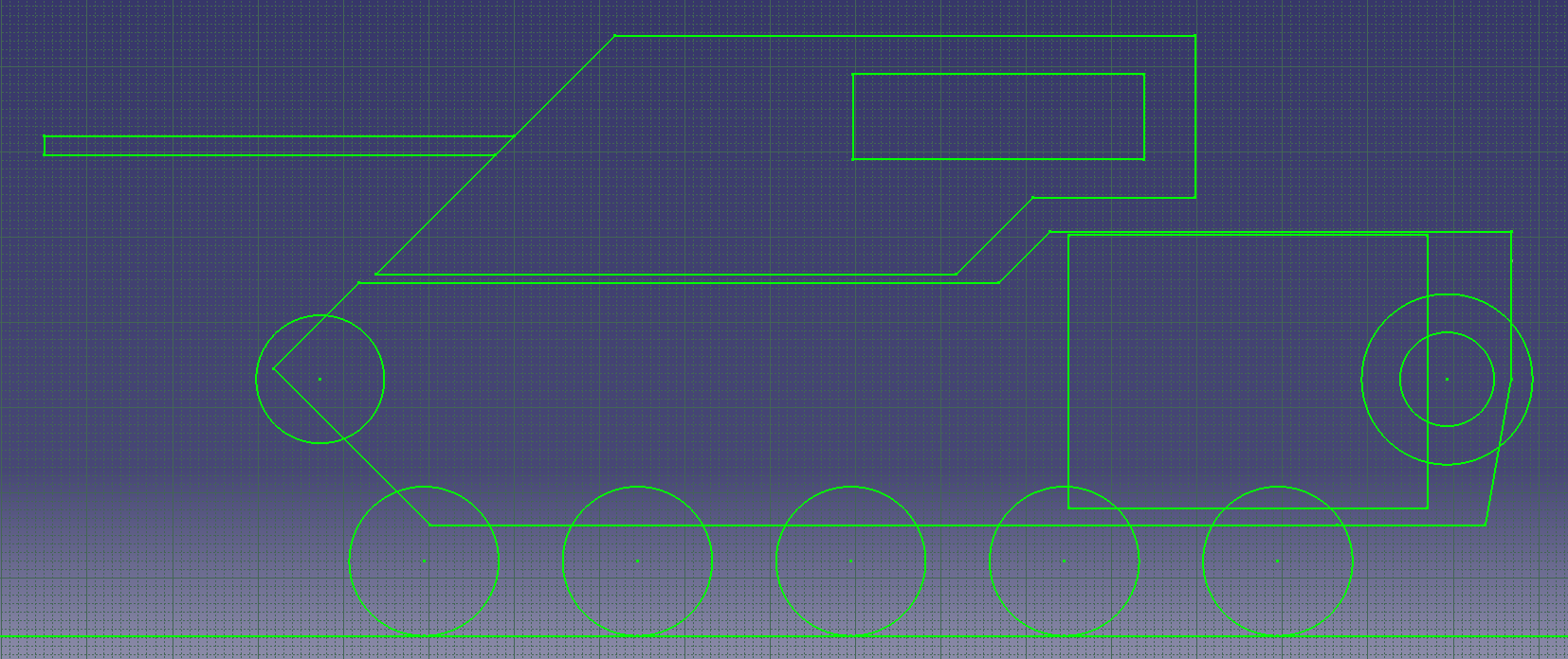
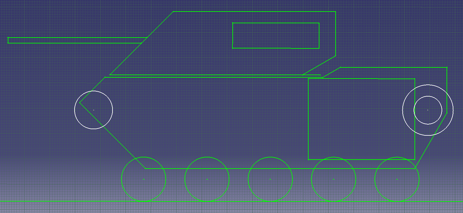
EARLY DESIGNS
05/16/2020 at 17:06 • 0 commentsBecause history matters
![]()
![]()
![]()
![]()
![]()
![]()
![]()
![]()
350KG RC TANK - PROGRAM : CHAROGNARD
Design and construction of a 350KG (700lbs) RC TANK, from scratch


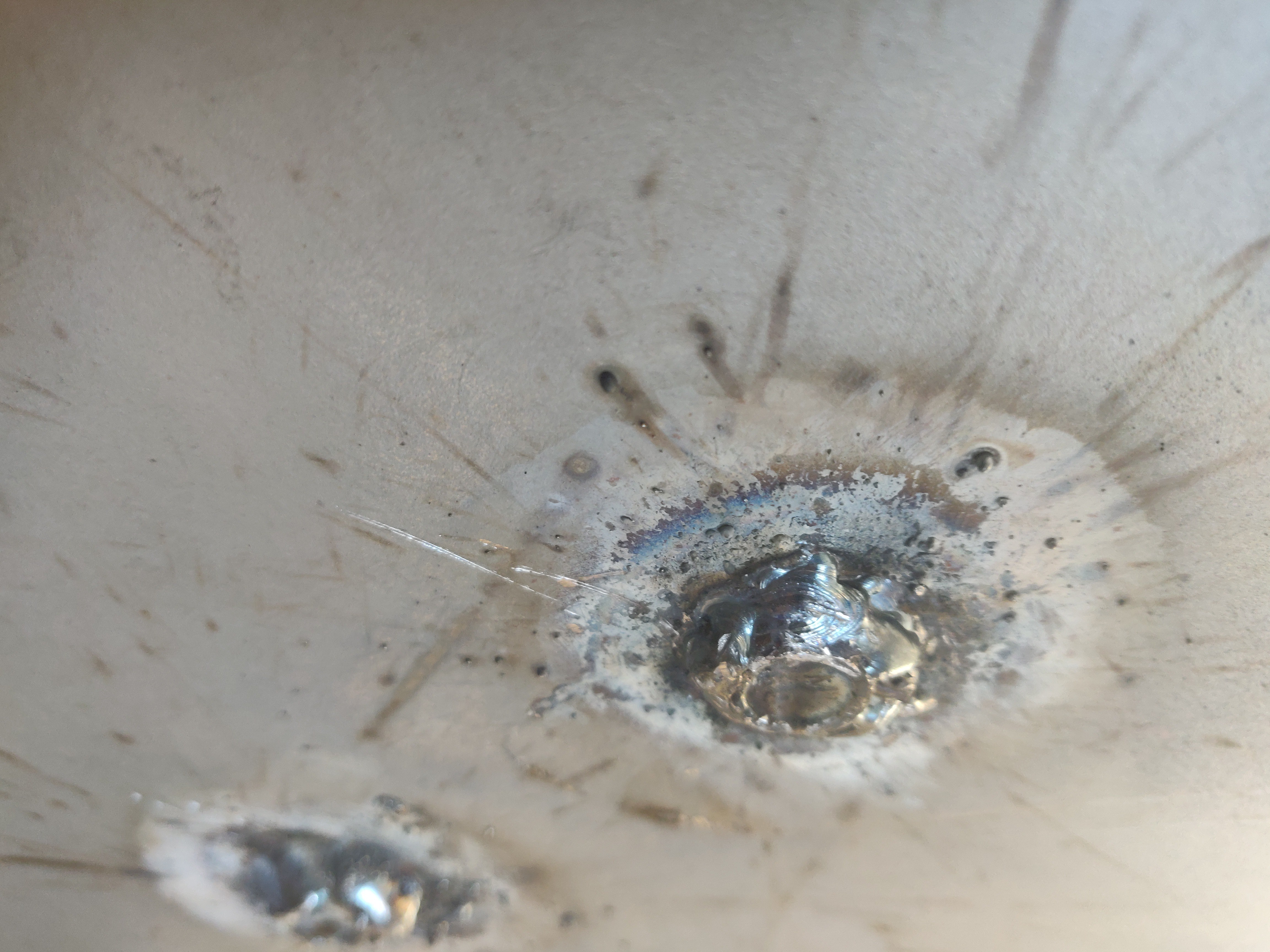 welding of the screws for engine mounts