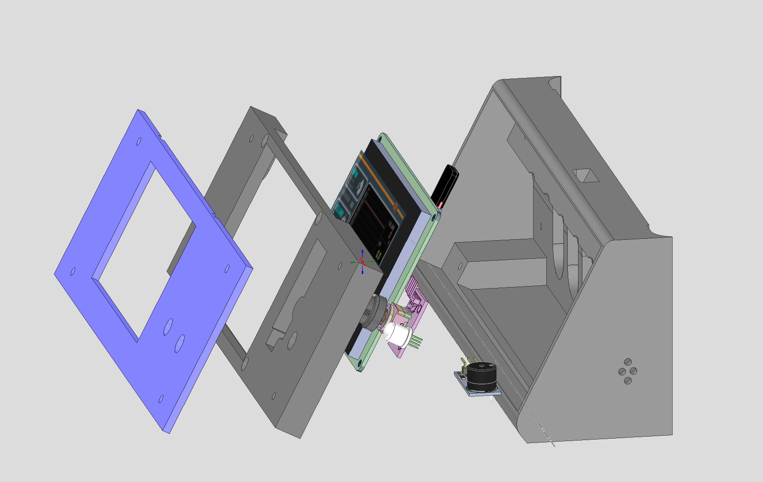
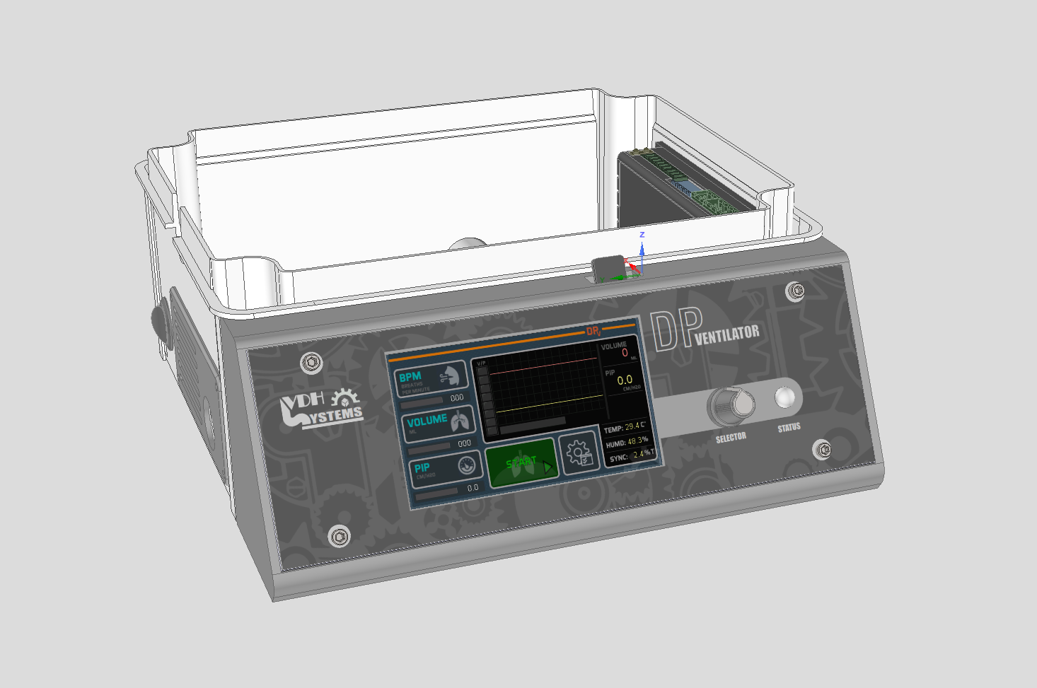
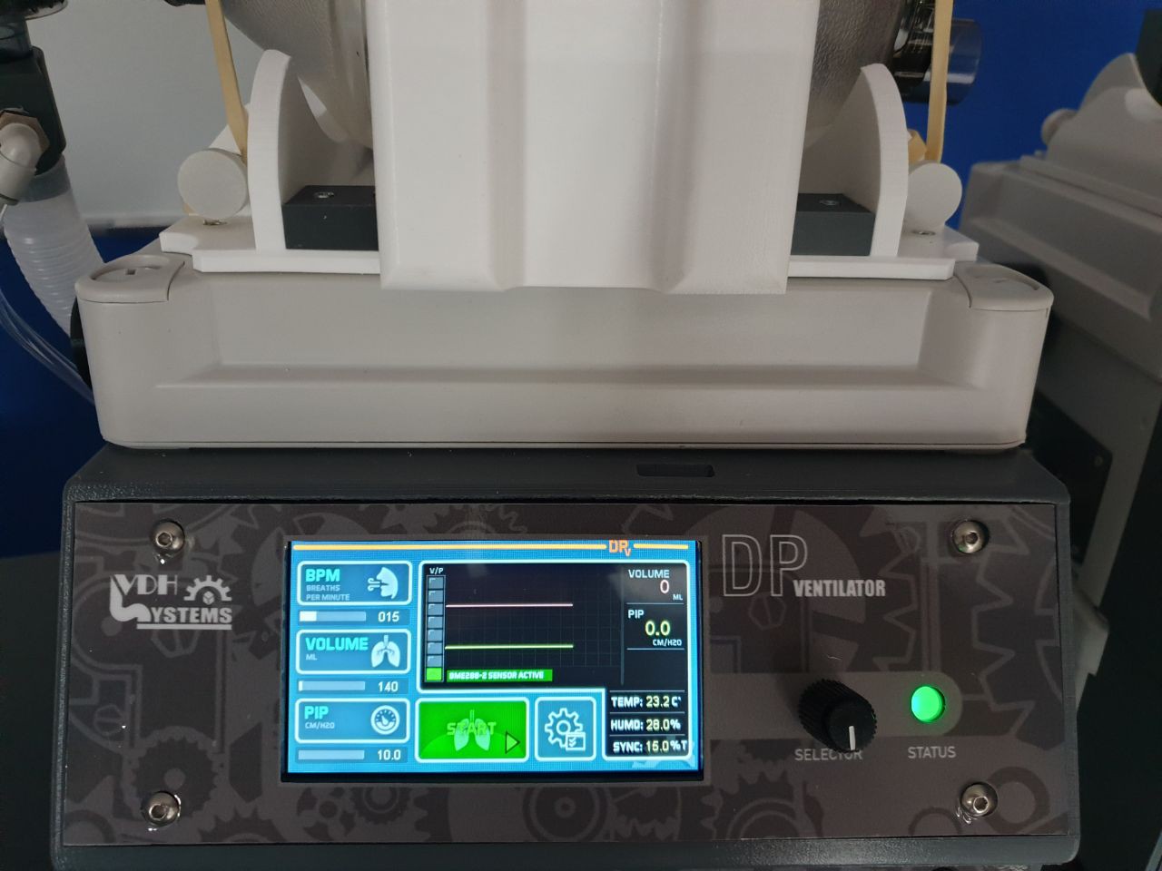
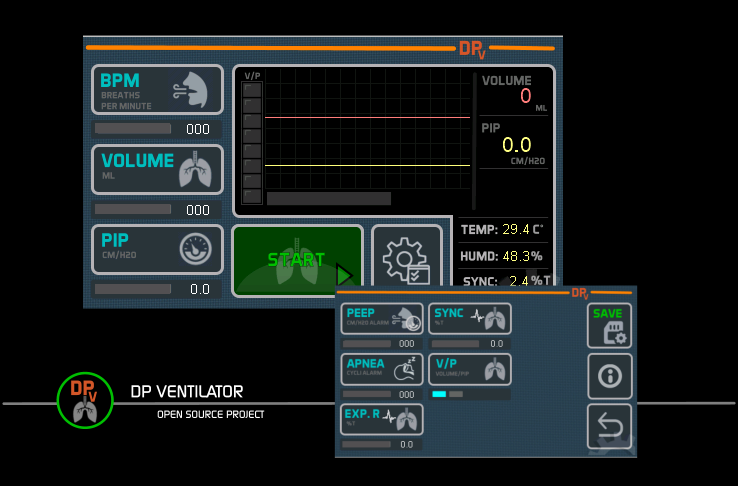
The Nextion HMI screens, everybody know them, excellent hmi interface with all the graphical source on the display side, so less resources on the arduino side. But one of the biggest problems, a decent communication in bought directions.
I did a whole research finding a decent communication but didn't find it, I wanted a simple communication without any of the libraries from Nextion.
Continuously writte data to the screen and getting data from the screen, easy expandable.
#define NXTSerial Serial2 // Serial port to connect with Nextion panel
Set serial port to use with the arduino board
voidNxtOpenSerial()
{
//This is for serial Nextion display.
NXTSerial.begin(19200);
}
To open the serial communication with the HMI display.
Example: Write 6 parameters to the Nextion screen.
repeat this routine on every 50ms and send only data when it changes to shorten your data transfer. Because you send just one line of data it stays very responsive.
Listen to the port if data is available, if so read char start message between (0xF0>0xFE) If found read and store next character until character 0x0A has been read. This is the end of the message. As you can see it is a very simple communication but it works very good.
Now lets check some data and do something with it.
                CheckNxtHex(0xF0,NXTparam);       // Read parameter data from 0xF0

                CheckNxtHex(0xF1,NXTstart);       // Read parameter data fron 0xF1 and do something
                if (NXTstart==1 && !NXTstartFlag)  {ee.active=!ee.active;NXTstartFlag=true;} // Toggle button (start/stop)
                if (NXTstart==0)                   {NXTstartFlag=false;}
and close communication
                NxtBufCnt = 0;

             }
          }
      }
    else
      {
        // WRITE DATA TO PANEL
        Nxt_Write();
      }
  }
I hope this explains a litle how I made a good and fast working communication with the nextion display.
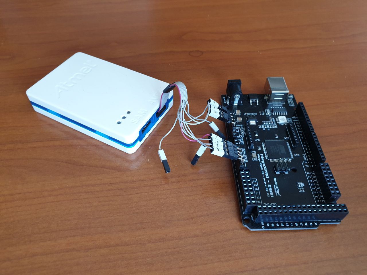
I am transferring all source from Arduino to Atmel Studio 7, many more possibilities to debug and stabilizing the software. On mega 2560 I use JTAG connection with Atmel debugger hardware. Connections are, 6 = reset pin (Do not know if it is needed) 4=5VDC pin 10=GND pin
first plug Atmel debugger in SPI (6pin connector) and select FUSE to JTAG, then power of and make selection as above.
Warning! if you do this changes boot loader will not work anymore, you still can fix this again with Atmel studio. So when debugging mega board you have to do these changes. If you want to fix boot loader again you have to download hex boot loader file from Arduino site and have to burn it with de SPI connector from within Atmel Studio software.
The reason to work with Atmel Studio, medical equipment needs to be undertaken that software is bullet proof , so debugging is very important, also some of the libraries needed to be fix with some small glitches.
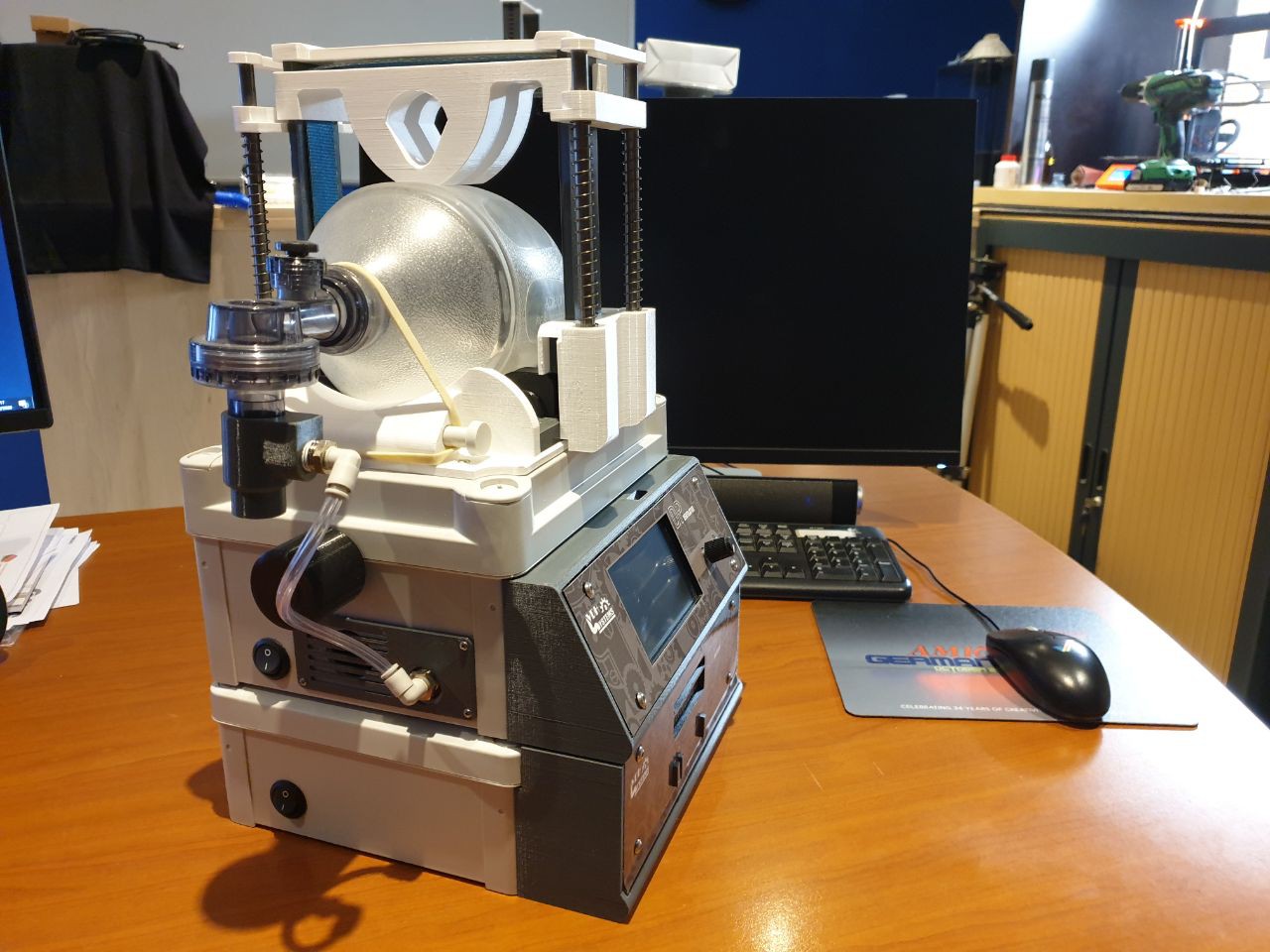
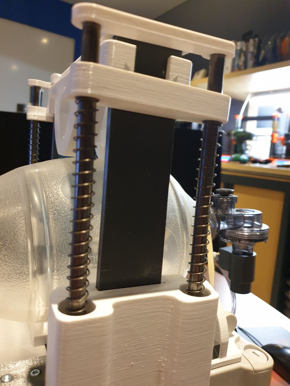
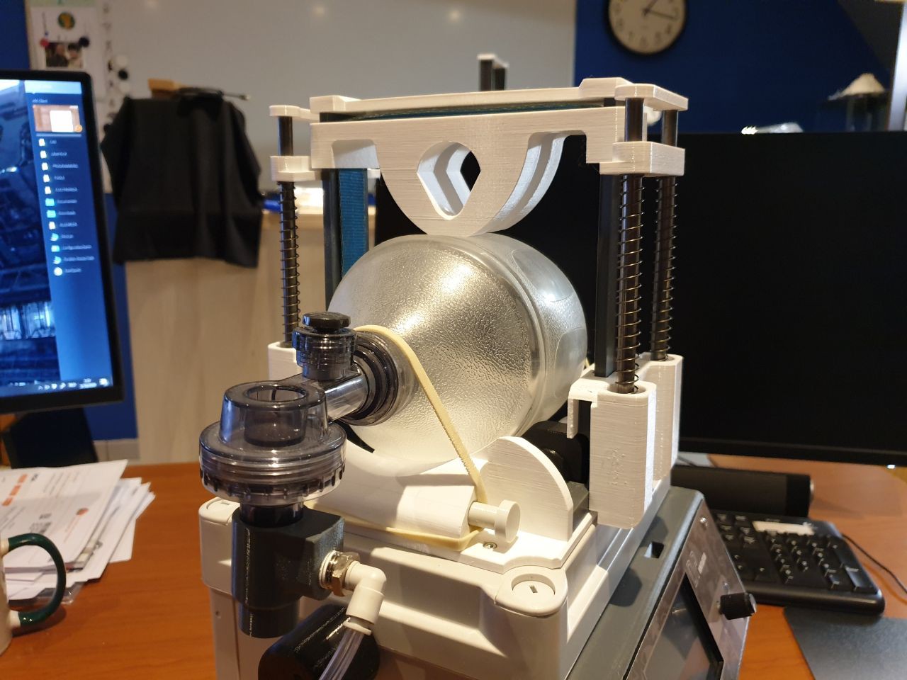
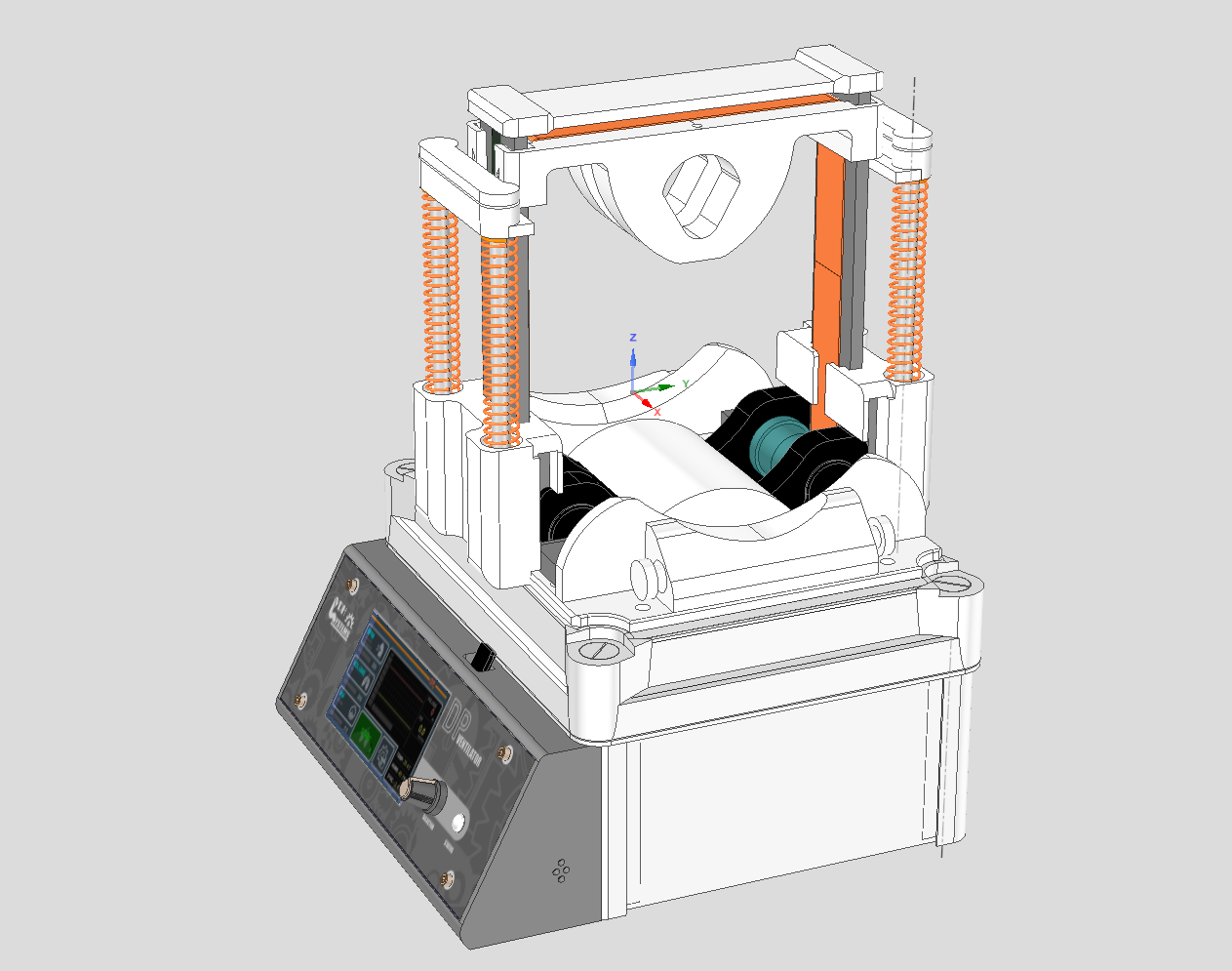
To move controlled in both directions Up and Down we used springs, this way we are fully guiding the press system on the amu-bag.
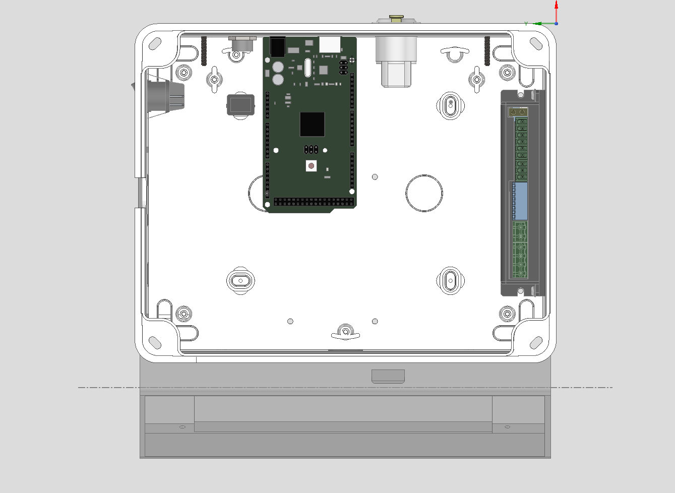
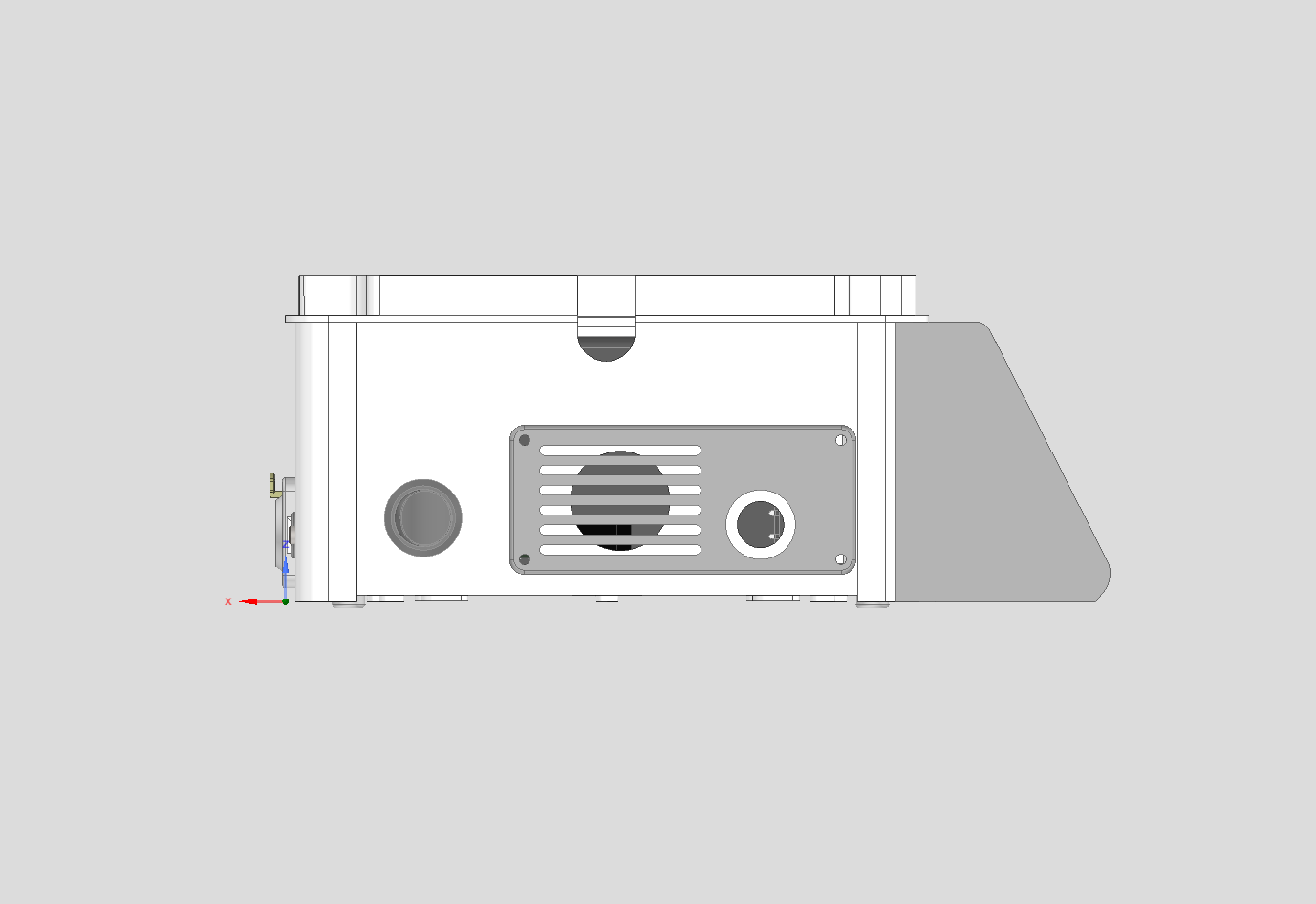
We take the cover of the box and made some things on it.
Every piece has been made to easily be removable. The motor Knob can be used when the machine is powered off to clamping the abu-bag between the two squeezers.
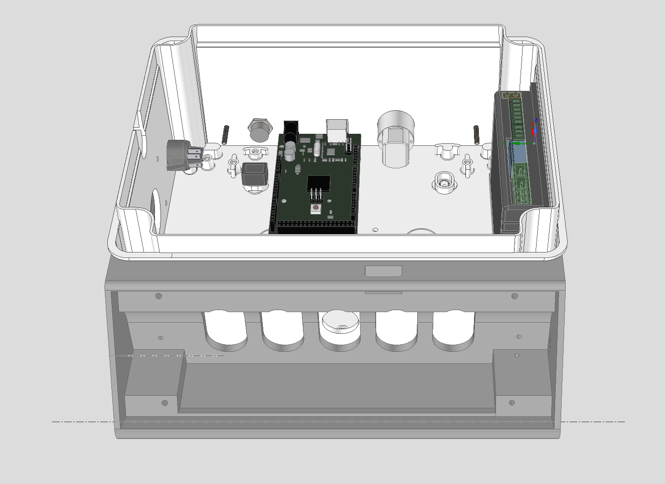
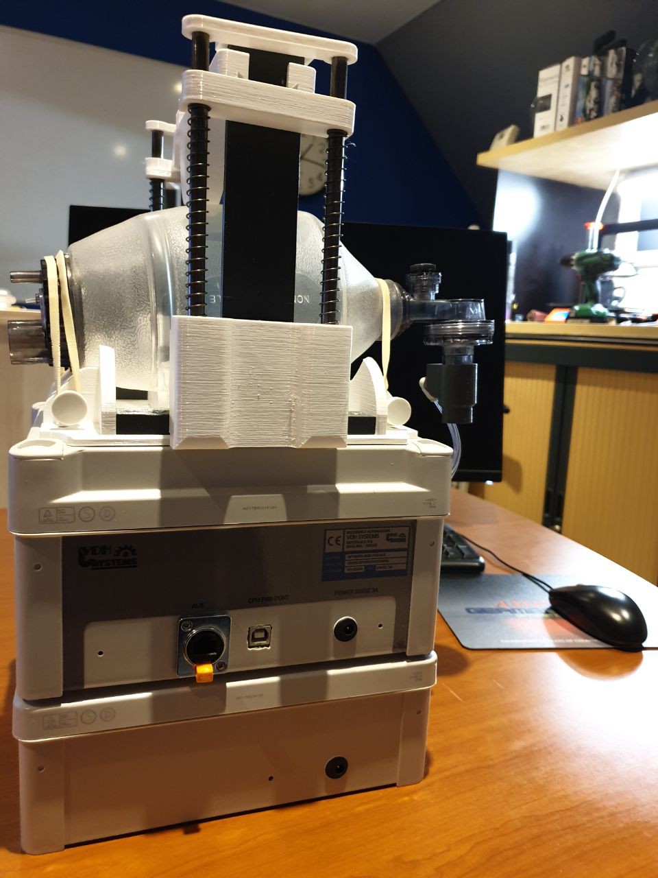
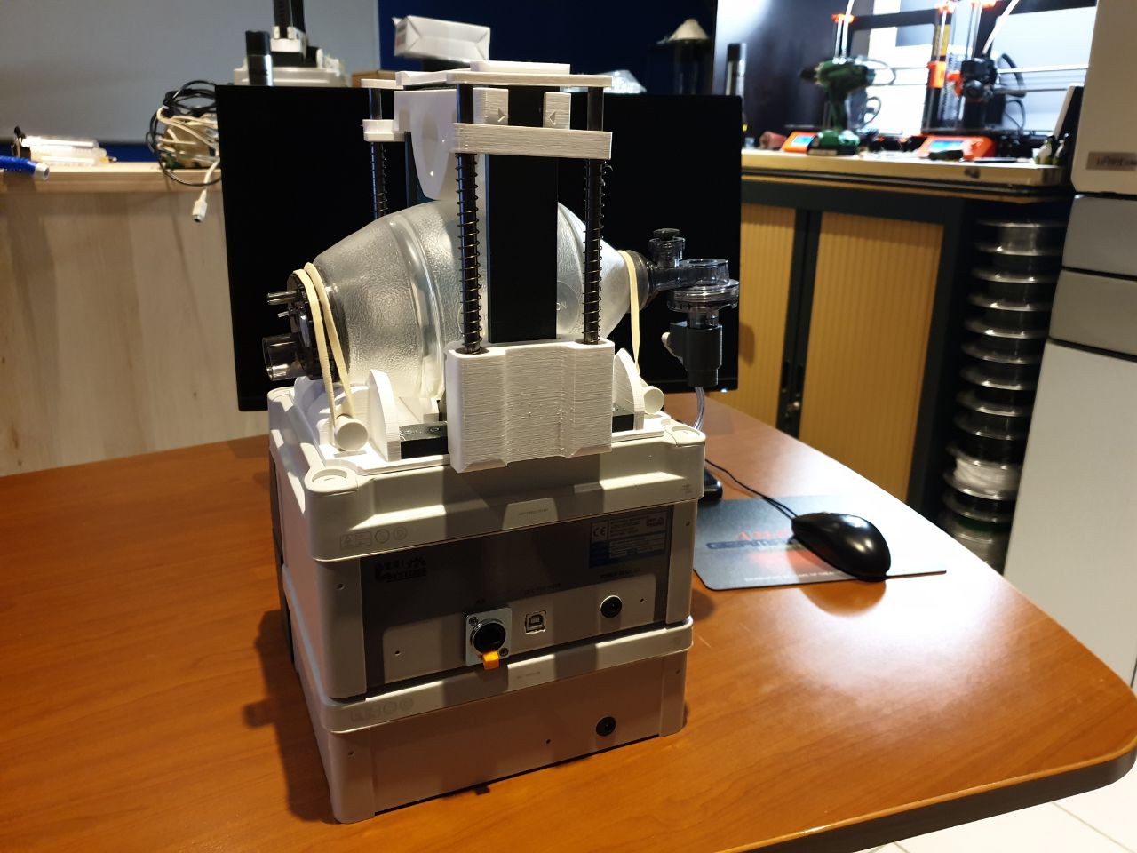
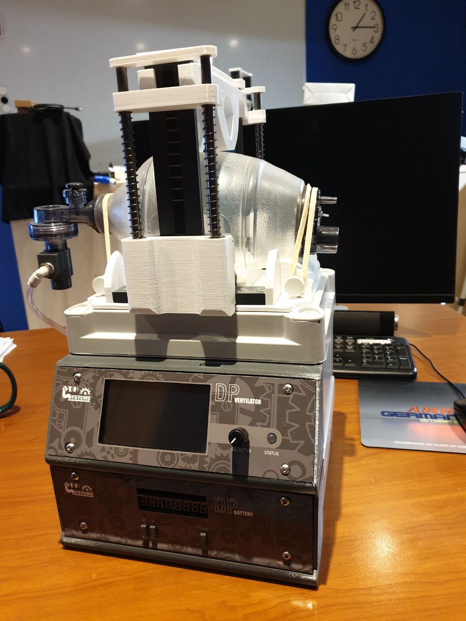
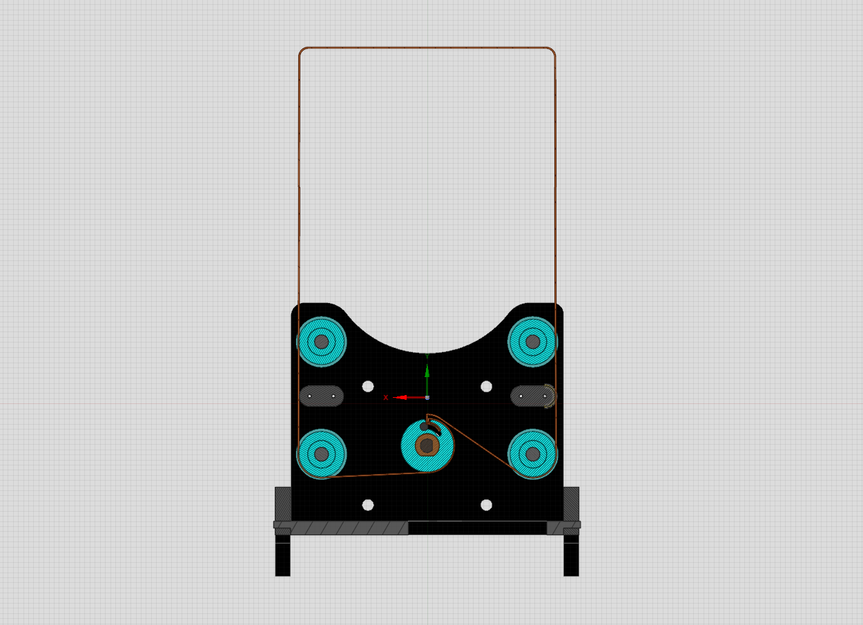
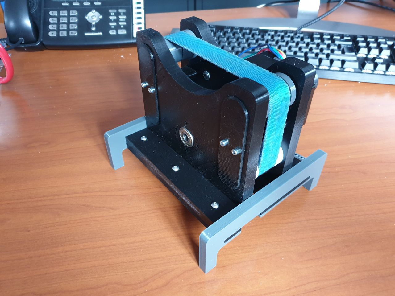
The mechanical table exists out of a strap belt, the whole mechanics has to be build into the enclosure on a easy way to get removed or inserted.
Th
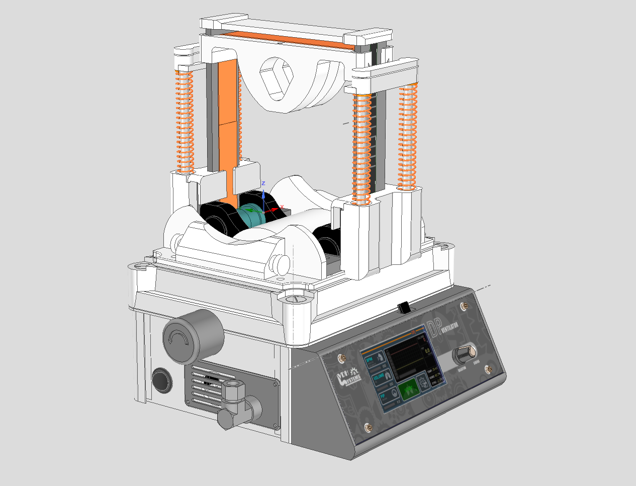
It's been build around a very strong stepper motor Nema 34 with 4.5Nm torck. The driver must be very silent so we needed to work in micro steps with enough power. After several tests with different motors this was the best result. It also needed to be double shafted because we wanted to work with a motor that we manually wanted to move to bring in the ambu-bag. The standard strap belt we used has a width of 20 mm and the thickness about 1 mm. You can find it in your local warehouse. Take the nylon one and if you cut it always use a burner to melt the ends.
Here you see how it is brought into the enclosure.
 dannyvandenheuvel
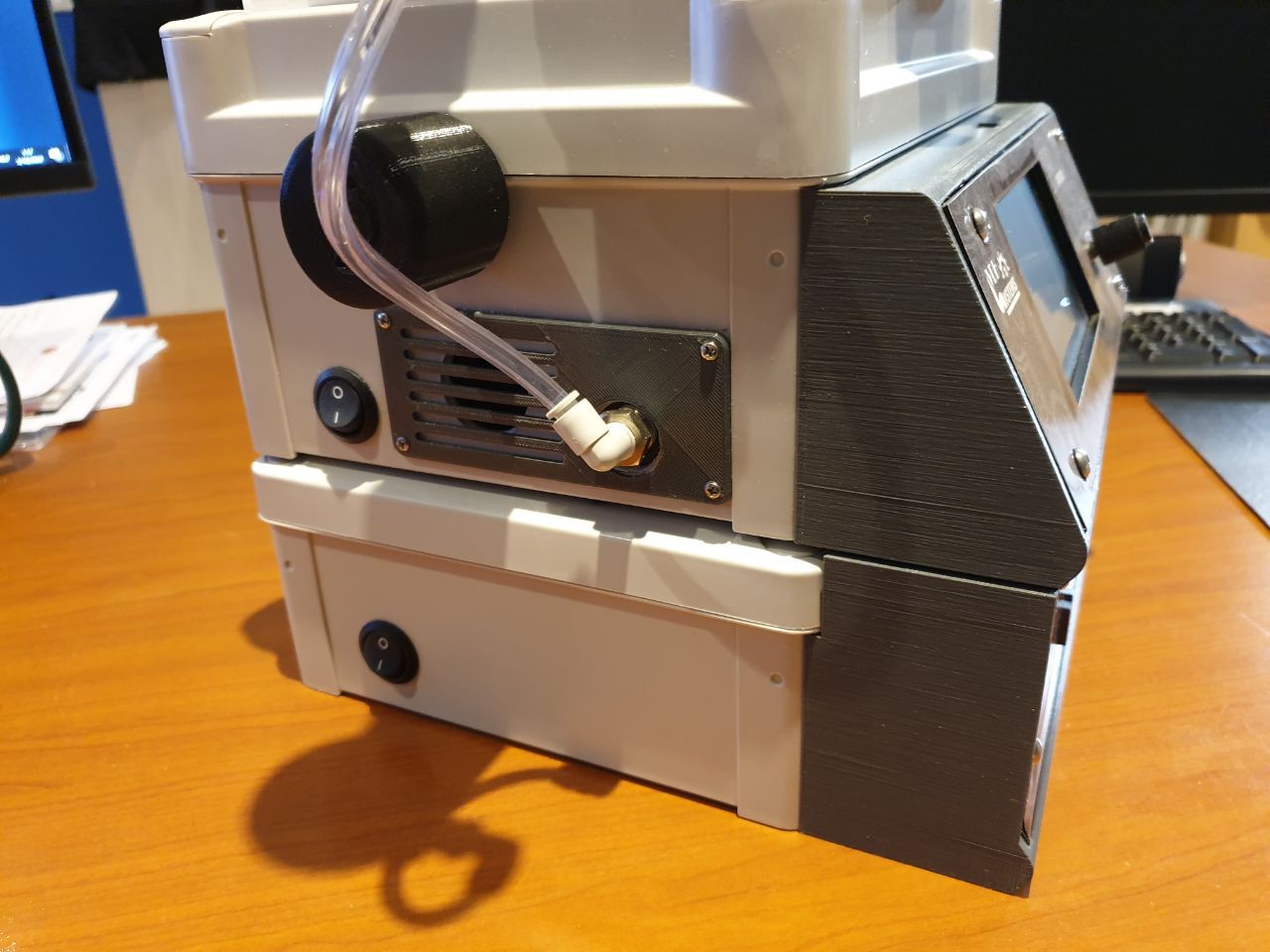


 I am transferring all source from Arduino to Atmel Studio 7, many more possibilities to debug and stabilizing the software.
 To move controlled in both directions Up and Down we used springs, this way we are fully guiding the press system on the amu-bag.

 The mechanical table exists out of a strap belt, the whole mechanics has to be build into the enclosure on a easy way to get removed or inserted.
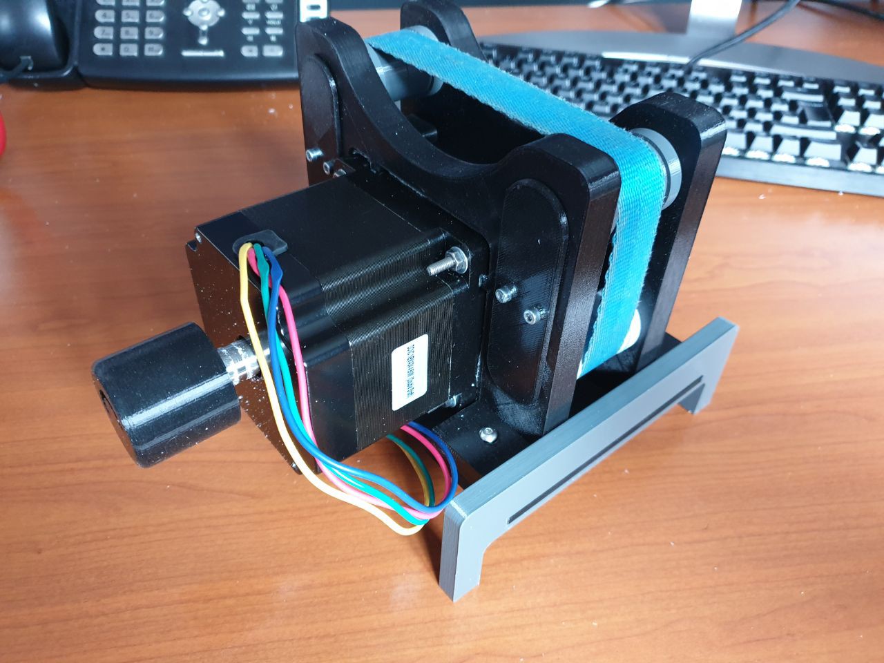
 It's been build around a very strong stepper motor Nema 34 with 4.5Nm torck. The driver must be very silent so we needed to work in micro steps with enough power. After several tests with different motors this was the best result. It also needed to be double shafted because we wanted to work with a motor that we manually wanted to move to bring in the ambu-bag.
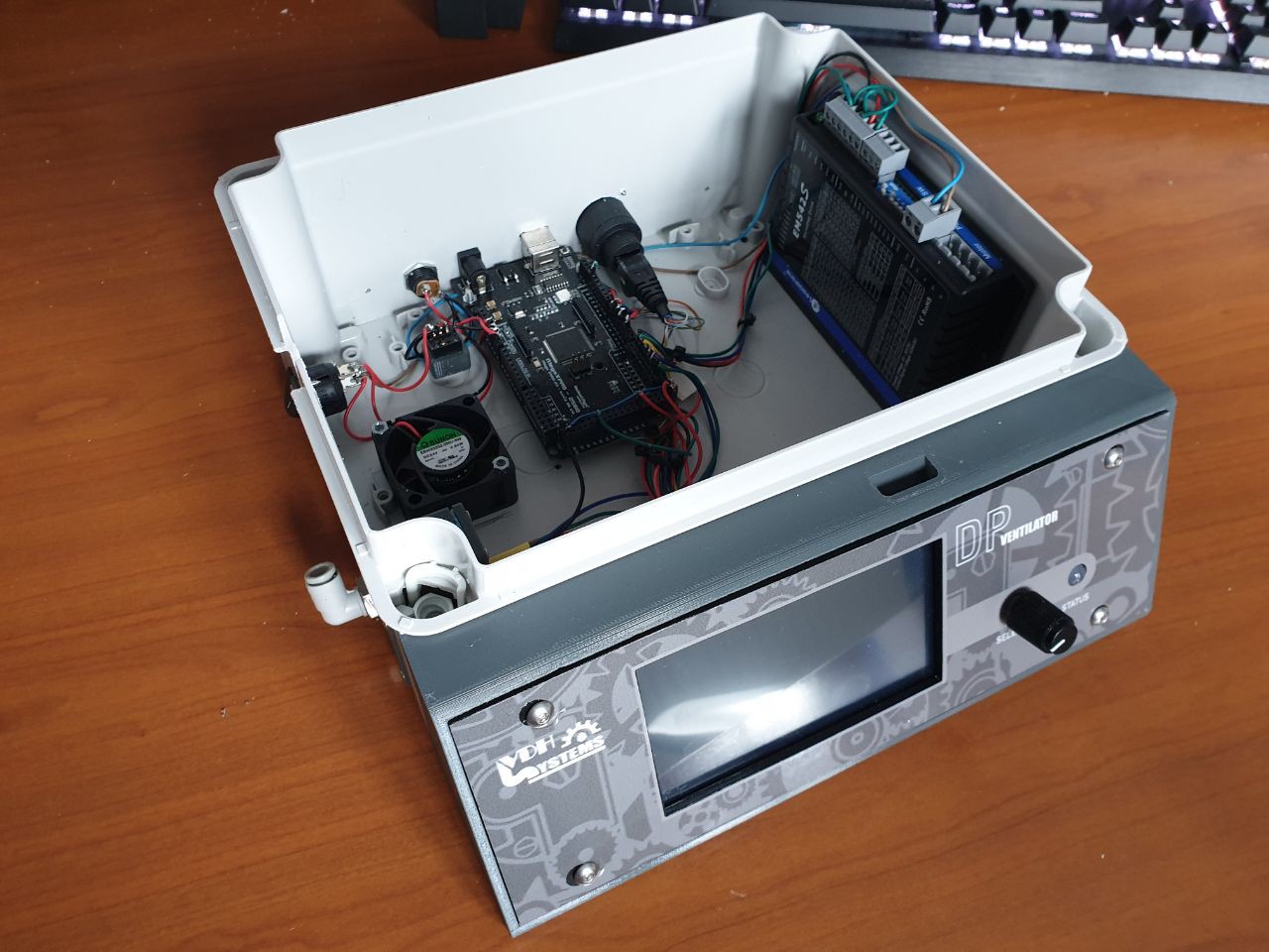

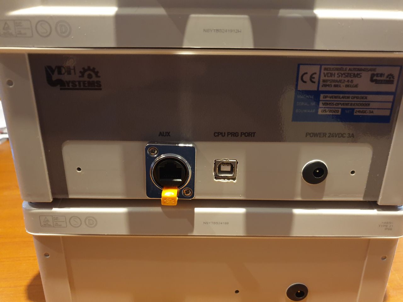
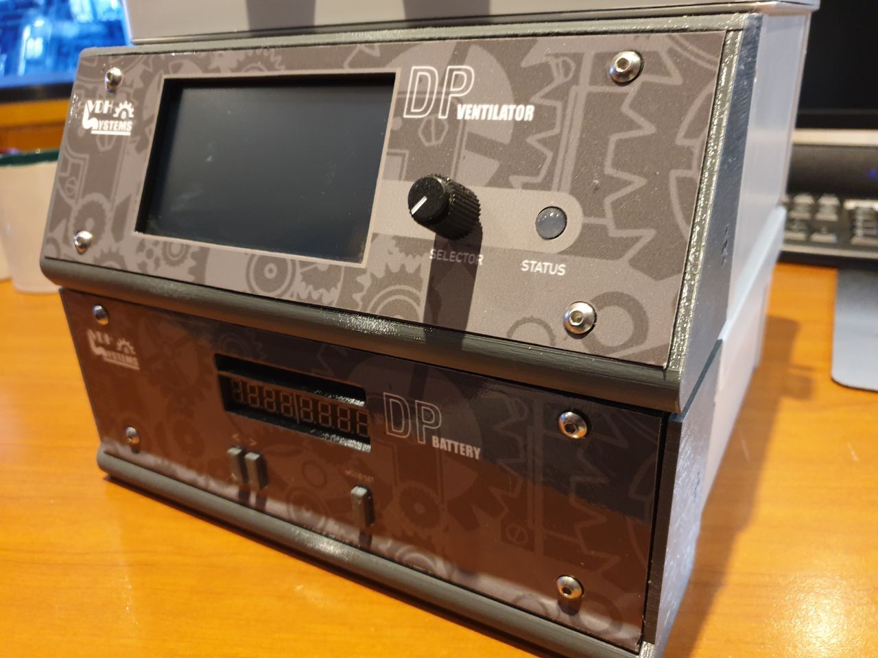
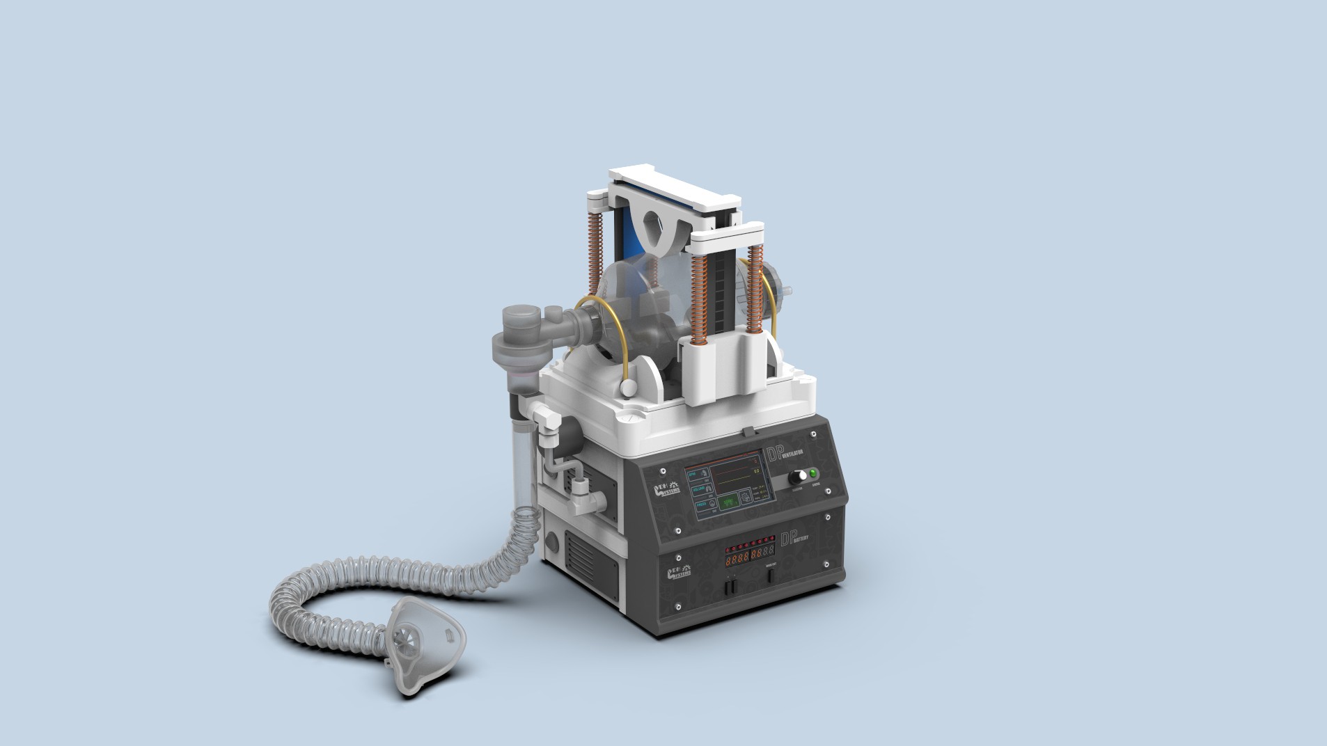
 This was one of my first questions, how I going to build it? Everything started with this enclosure.