-
Thermal Test Plan
09/20/2020 at 16:06 • 0 commentsThe goal of the the thermal test plan is to evaluate the thermal performance of the existing two hot plate and new "tube" heat transfer prototypes against the OpenFluidWarmer design requirements.
Heater Set Point Test
Determine heater set point required to achieve 38°C outlet temperature at the following conditions (max allowable heater set point of 100°C):
- 4°C inlet temperature, 20ml/min
- 20°C inlet temperature, 20ml/min
Flow Rate Test
Determine the maximum possible flow rate that keeps outlet temperature above 20°C at the the following conditions:
- 100°C heater set point, 4°C inlet temperature
- 42°C heater set point, 4°C inlet temperature
Background
- 4°C is the storage temperature of some blood products
- 20°C is assumed room temperature
- 38°C is assumed human body temperature
- 42°C is the assumed lowest temperature at which hemolysis begins to occur
- 100°C is near the maximum allowable temperature of the prototype insulating materials
- 20ml/min is the lowest "fast" flow rate determined by Field Ready's previous "Low-cost Fluid Warmer" project
Test results will be posted later this week.
-
A promising new heat transfer concept
09/18/2020 at 03:15 • 0 commentsIt's always encouraging to arrive at a promising new design concept this far into product development. It signals to me that all the work I put into developing and testing earlier prototypes (that have resemblance to commercially available IV fluid warmers) was an exercise in "learning the rules". Now that I know the rules, it's much easier to imagine new ways to break them.
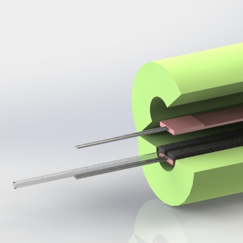
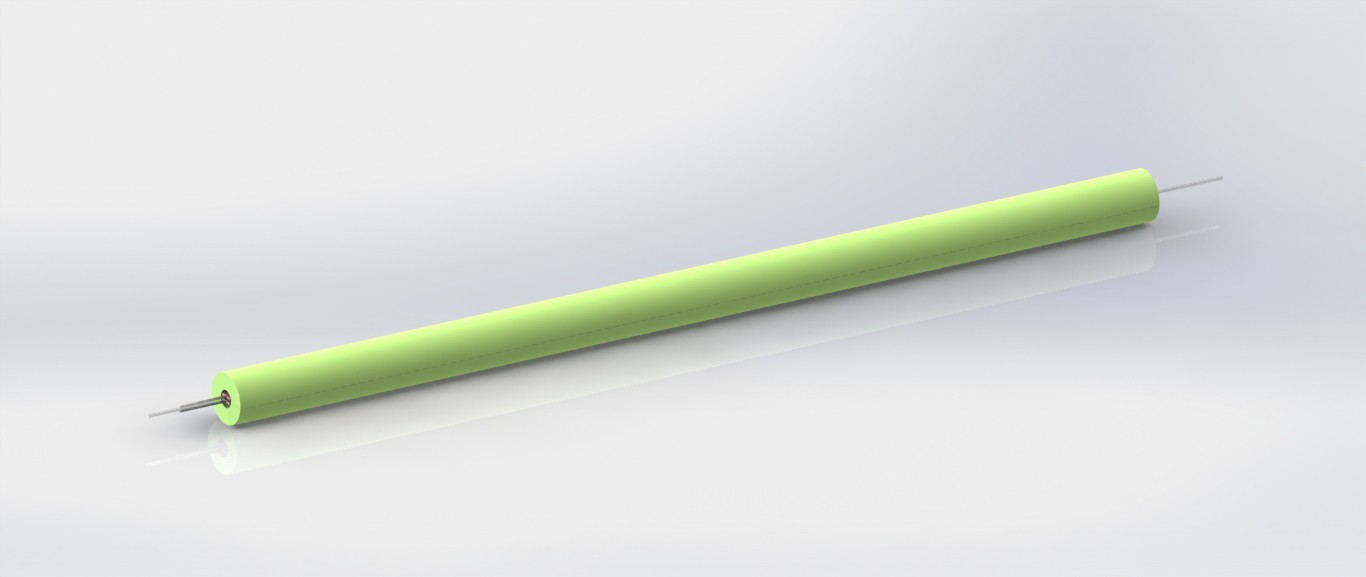
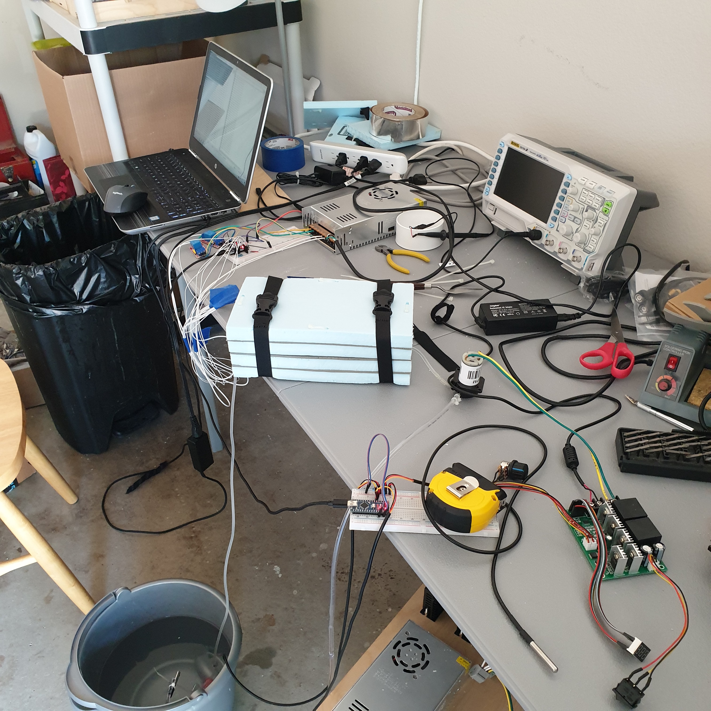
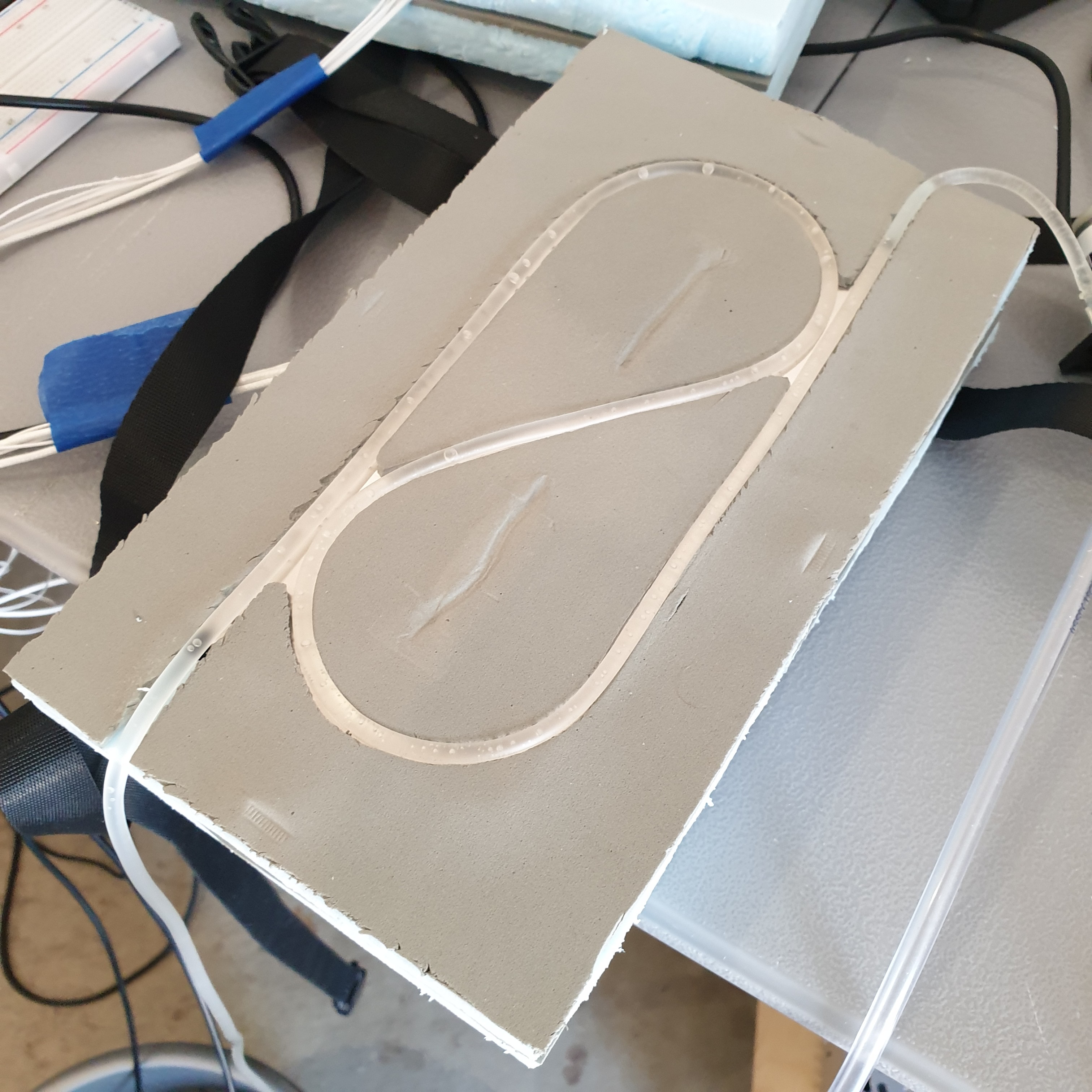
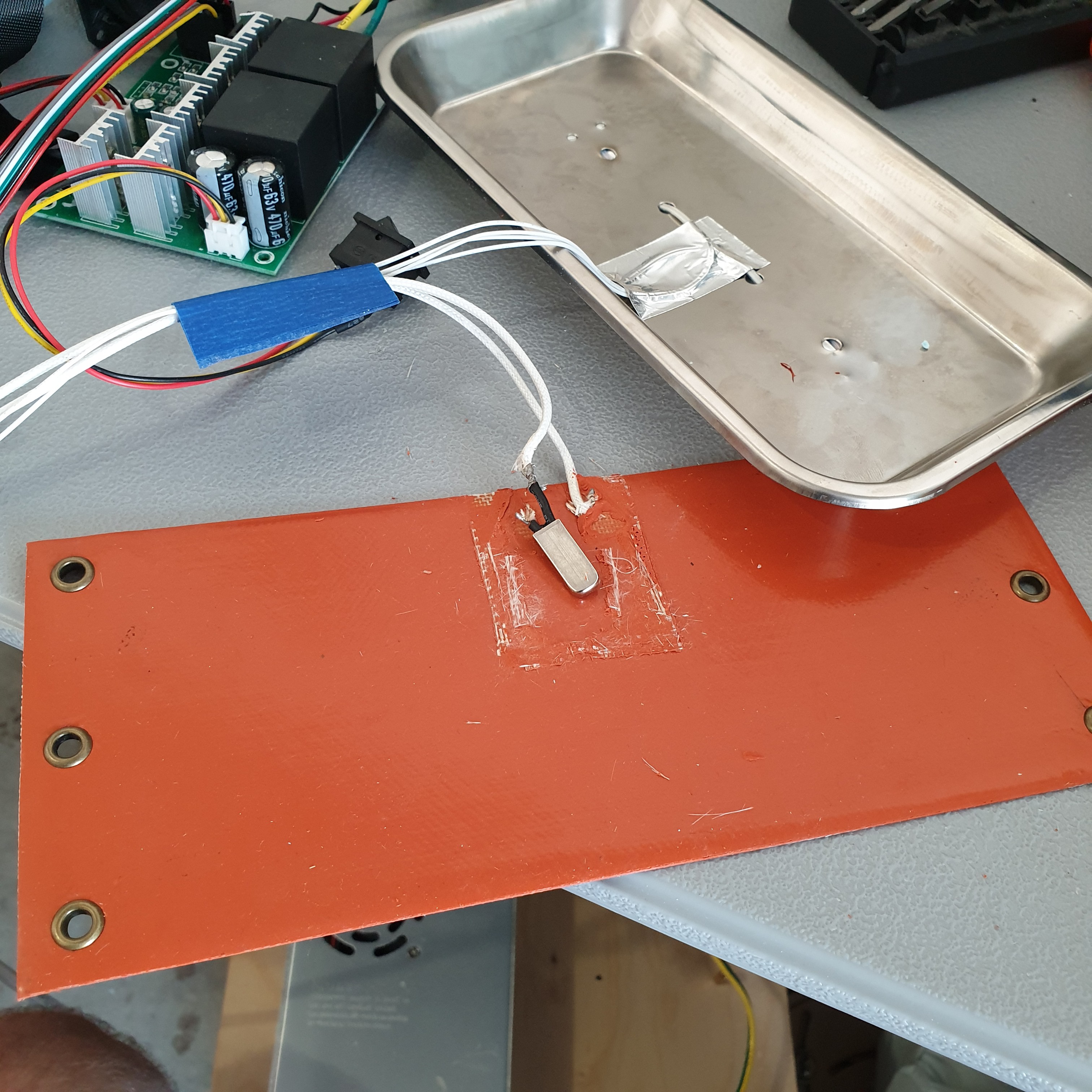
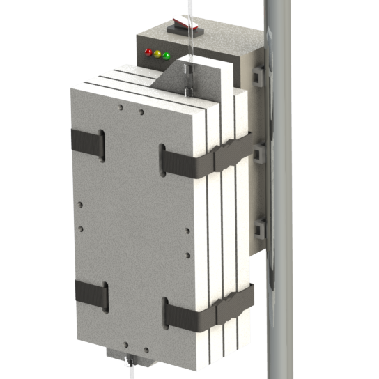
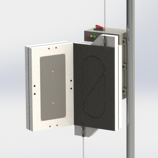
This new IV fluid warmer heat transfer concept, depicted in the images above, is my latest attempt at breaking the rules. It has potential to be cheaper and perform better thermally than the existing two hot plate design. It uses two low cost silicone pad heaters for deicing windshield wipers (didn't even know they were a thing, but they are readily available online) on two sides of the IV tube. Using these long, thin heaters results in a thermal contact area between the heater and the IV tube that is double the existing design. So potentially, these heaters do not have to be heated to as high of a set point as the existing design to achieve a similar rate of heat transfer to the fluid. While this new concept uses double the length of IV tubing, it can be bent to whatever shape is needed and allows the full length of tubing to be used (i.e. doesn't double 24in of tubing back on itself to result in only 12in of length).
It may be that using double the length of IV tubing is a deal breaker on this design, but there is always opportunity to not use the full length of the silicone heater and still achieve more thermal contact area between the heater and IV tube than the existing two hot plate design.
Heaters have already arrived. Waiting on the thermistors to arrive so I can more accurately measure heater temperature. Should have thermal test results for this late next week.
-
Medical Use, Prototype Updates, Demonstration
09/17/2020 at 04:52 • 0 commentsThis video explains the basics of how and why IV fluid warmers are used, describes recent updates to the OpenFluidWarmer prototype, and gives a short demonstration on how to operate the OpenFluidWarmer.
-
Thermal Peformance Testing - Round 2
08/29/2020 at 16:26 • 0 comments![]()
The second round of performance testing with this device shows promising results. The main change to the system since the last round of tests is that the built-in 65 degC thermostat has been removed from the silicone pad heaters. The thermostat was previously limiting the max temperature measured by the thermistors at the hot plates to 48 degC. During this round of testing, the max temperature measured by the thermistors at the hot plate was 110 degC.
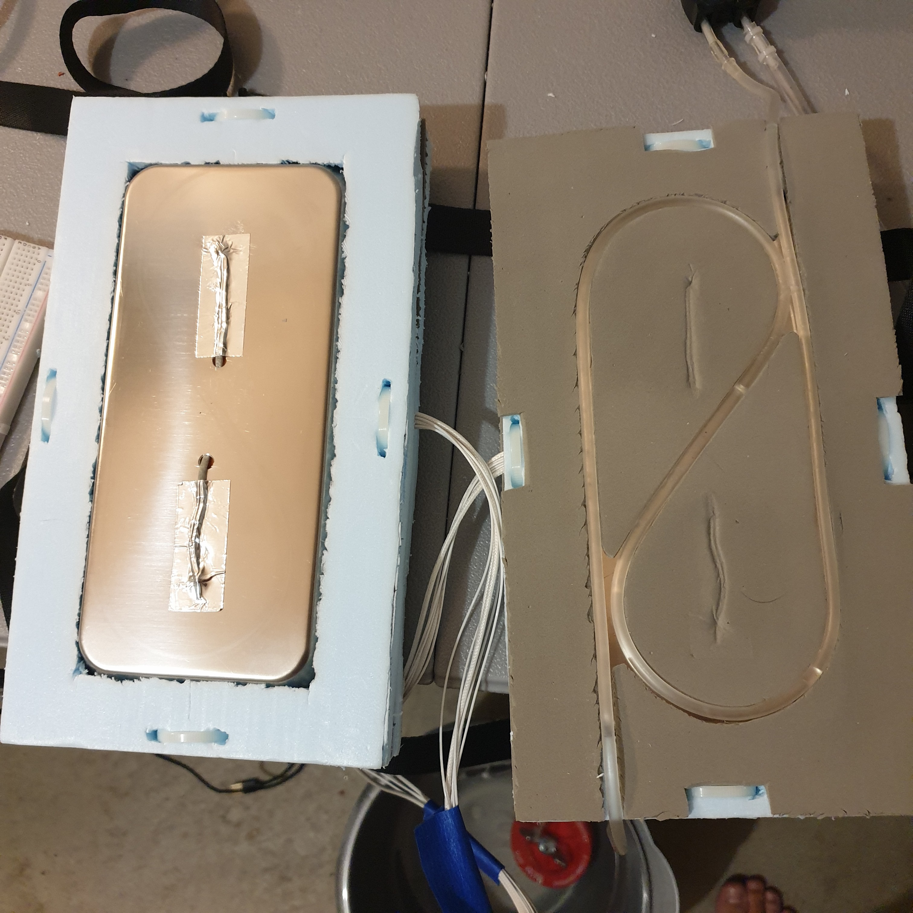
More background on the thermistor locations and length of IV tubing in contact with the hot plates is needed in order to give full context to the results. Two thermistors at located near the top and bottom of each hot plate and on the same side of the plate as the IV tubing. The thermistors are attached to stainless steel tray of the hot plate using foil tape tape. In the image below you can see them on the left hot plate. For the right hot plate, the thermistors are underneath the foam at similar locations. Each hot plate heater is controlled independently based on the average reading of the two thermistors. The length of tubing in contact with the hot plates is 660 mm (26 in).
![]()
The first test involved determining what hot plate temperature set point and flow rate was required to heat room temperature water to 38 degC. I eventually had to turn pump speed down to 50% in order to get a significant fluid temperature rise with a heater-off set point less than 90 degC.
Test parameters and results of the first test:
- inlet temperature, 27.5 degC
- outlet temperature, 38.0 degC
- total fluid temperature rise, 10.5 degC
- pump speed, 50%
- fluid flow rate, approximately 32.5 mL/min
- heater-off set point, 88 degC
- heater-on set point, 86.5 degC
- max observed temperature, 92 degC
The second test involved determining what hot plate temperature set point was required to heat ice cold water to 38 degC. It was able to achieve a outlet temperature of 27.5 degC at a heater set point of 105 degC. I wasn't confident how much higher I could push the heater before degradation to the polystyrene insulation foam so I stopped at the 105 degC set point. Inspection after this test showed no damage to the polystyrene so I plan to push the set point higher on the next round of testing.
Test parameters and results of the second test:
- inlet temperature, 4.5 degC
- outlet temperature, 27.5 degC
- total fluid temperature rise, 23 degC
- pump speed, 50%
- fluid flow rate, approximately 32.5 mL/min
- heater-off set point, 105 degC
- heater-on set point, 103.5 degC
- max observed temperature, 110 degC
92 degC and 110 degC max observed temperatures during the two tests is far above when hemolysis can begin to occur at 42 degC. Until I have the capabilities to prove that hemolysis does not occur at the max temperatures, it is recommended that the device not be used with red blood cell and other blood products damaged by temperatures above 42 degC. This relaxation in requirements is needed to maintain the strategy of heating the fluid through standard PVC IV tubing (i.e. not requiring a custom/expensive sterile in-line high heat transfer module) and using up minimal length of IV line through the device. A rethinking of the OpenFluidWarmer may be needed to achieve the original product requirements.
The next round of testing will identify what heater temperature set point is required to achieve 38 degC outlet temperature with a 4 degC inlet temperature.
-
Thermal Performance Testing - Initial Results
08/13/2020 at 00:58 • 0 comments![]()
![]()
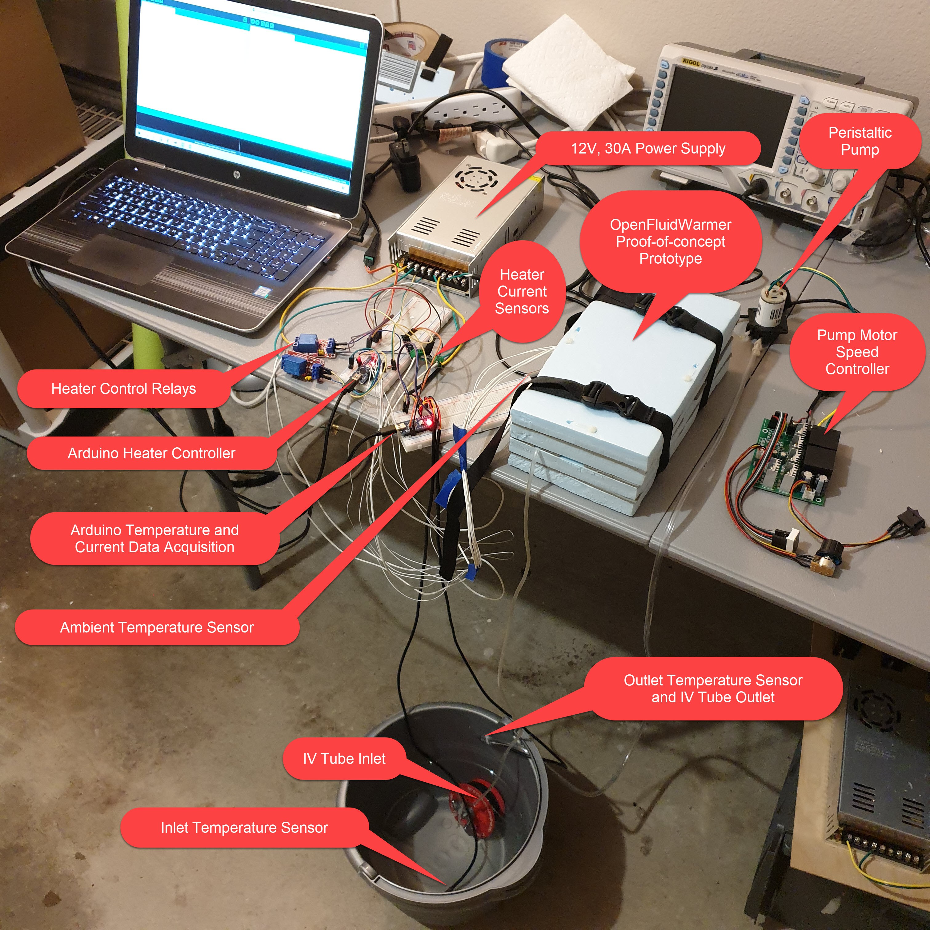
Thermal performance testing with IV tubing sandwiched between two 100W silicone heaters has continued over the last week.
I am waiting to publish test data until I make one more modification to the device. During testing I discovered that the silicone heater pads have a built-in thermostat switch that opens when the thermostat reaches 65 degC. I have since removed the thermostat so I can have more refined control over the heat generation for the next few tests.
![]()
As expected, initial tests indicate that thermal insulation of the PVC tubing greatly limits the rate of heat transfer to the fluid. The simplest solution to this would be to increase the length of tubing that is in contact with the hot plates. Unfortunately, initial results indicate that at least three times the current tubing length would need to be in contact with the hot plates to achieve the desired outlet temperature of 38 degC. Further testing without the thermostat on the heater pads may change these results.
The IV tubing I am using is from a veterinary infusion fit that I bought online. It is a PVC tubing with 3mm ID and 0.5mm wall thickness.
I put the peristaltic pump motor on a speed controller to achieve lower flow rates. Even at 50% speed, there was no significant change to the temperature rise between the inlet and outlet.
It is clear that the heater will need to be heated to a setpoint above 42 degC in order to achieve the desired fluid outlet temperature with the current device configuration. Unfortunately, 42 degC is the temperature at which hemolysis can begin to occur in red blood cell products. It is beyond the current capabilities of this test setup to determine if temperatures in excess of 42 degC are present and in contact with the fluid at heater setpoints above 42 degC.
-
Bang-bang Control
08/04/2020 at 04:14 • 0 comments![]()
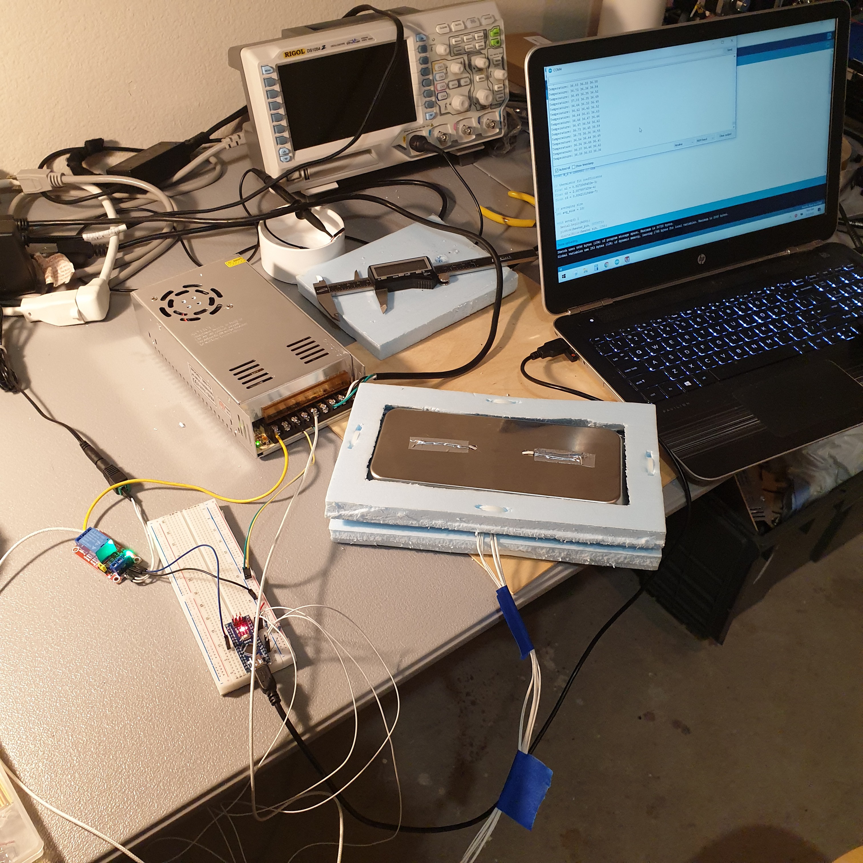
The test setup depicted in the image is representative of one of the hot plates of the two hot plate IV fluid warmer design that is being evaluated. A 100W heater silicone pad is sandwiched between a layer of polystyrene insulation foam and a stainless steel medical tray. Two 100kOhm thermistors are fed through holes in the stainless steel tray and mounted to the side of the tray opposite the heater with aluminum tape. As part of the two hot plate IV fluid warmer design, the IV tubing will be in direct contact with the hot plate on the same side as the thermistors.
The 100W silicone heater pad and two 100kOhm thermistors are operating successfully with a bang-bang feedback controller. The controller is programmed to turn on the heater if the device is below 36degC and turn it off when the device reaches 36.25degC. Cooling is achieved by natural convection for this test setup. Because the heater and thermistors are on opposite sides of the stainless steel medical tray, the thermistors detect a temperature change about four seconds after the heater has been turned on. After the heater shuts off at 36.25degC, it continues to transfer heat to the hot plate. The hot plate starts to cool down after reaching a maximum temperature near 38degC. Since the heater and stainless steel tray are sandwiched between two layers of polystyrene, the lowest thermal resistance path is through the stainless steel plate out to ambient air.
It was not my original intention to implement a bang-bang controller, but I am now considering it based on the potential cost savings and simplicity. Up until this point, I have been expecting to implement a PID control algorithm with a 3D printer heater, power FET module. In total, the power FET modules are about $4 USD (5% of total material cost) more expensive than the relay modules needed for bang-bang control. It wasn't until I realized that the power FET modules I had bought require a minimum input signal of around 7.5V (Arduino only outputs a 5V PWM signal) that I considered bang-bang control just to get something working. Bang-bang control has the disadvantage of always drawing max current of around 16.6A combined for both 100W, 12V heaters. Even so, I am looking forward to testing bang-bang control with the two heater plate prototype.
The next step is to complete the two heater plate proof-of-concept prototype and test it with the fluid temperature rise test setup that I described in the last project log. All materials have arrived and the majority of the fabrication is already done. It will take about two to three more evenings to get everything setup and the first set of performance data collected.
-
Fluid Temperature Rise Test Setup
07/26/2020 at 21:42 • 0 comments![]()
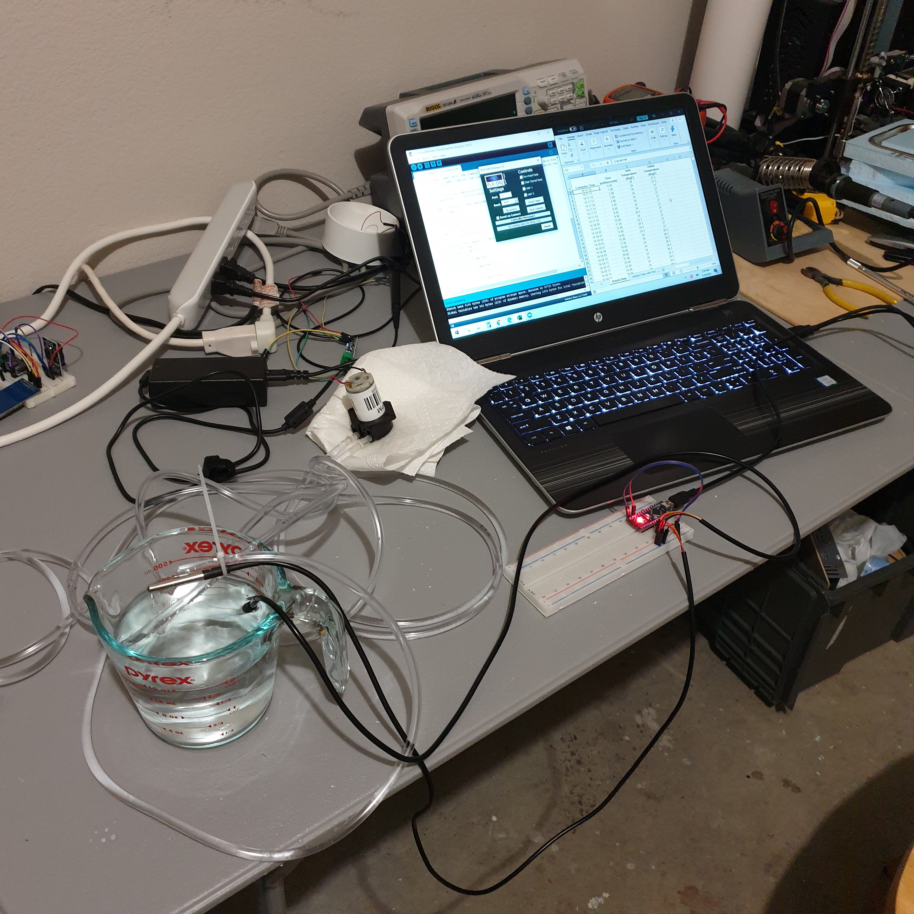
I recently developed the test setup for measuring the fluid temperature rise through the OpenFluidWarmer prototype. A peristaltic pump, typically used for aquarium dosing, pumps fluid through the tubing at a rate of approximately 65ml/min. Two DS18B20 measure fluid temperature at the inlet and outlet of the tubing. An Arduino Nano captures the temperature data from both sensors and sends the data through serial to the computer. I use the PLX-DAQ macro spreadsheet to pull the serial data directly into Microsoft Excel. Once in Excel, it is very easy to manipulate and plot the data.
The actual testing will include several differences that I did not think were needed to ensure proper operation of the test equipment and instrumentation. The pump will draw fluid from an ice bath. This will ensure a constant fluid inlet temperature and approximate the 4degC initial temperature typical of blood products. An ambient temperature sensor will be added to keep record of environmental temperatures between tests. In addition, the system will be allowed to achieve a thermal steady state condition over a period of ten minutes.
This test cuts corners for convenience and is not necessarily representative of how the OpenFluidWarmer would perform with actual blood products. The density and thermal capacity of water is different from whole blood and packaged red blood cells. Hardware store vinyl tubing is used instead of medical grade IV tubing. The pumping action of the peristaltic pump may add a small fluid temperature rise. The inlet temperature will be at 0degC rather than the 4degC typical of the initial temperature of blood products. So the purpose of this test is not to determine with great accuracy if the current OpenFluidWarmer can meet the fluid warming requirements, but whether it is reasonable to think that it could. If not, options are to either accept lower performance or go back to the drawing board.
-
Initial Mechanical Design
07/20/2020 at 04:59 • 0 comments![]()
This initial OpenFluidWarmer mechanical design is a result of the last month of research. Each product analysis exercise (cost, souring, heat transfer, competitive analysis, design requirements, etc.) helped to identify design opportunities that I would not have found otherwise. Perhaps equally important, they helped to eliminate the many sub-optimal solutions that were floating around in my head. Because of all the upfront research, I had about 80% clarity on what the mechanical design would look like prior to staring the 3D modelling and working through the dimensional details.
You might have noticed that this new mechanical design has almost no resemblance to the metal tube enclosure prototype that I proposed previously. The main reason I moved away from the metal tube design is because of the poor heat transfer rate from the heaters to the IV fluid. More specifically, the new design requires less length of IV tubing through the device in order to transfer the same amount of heat to the IV fluid. This higher heat transfer coefficient between the heat source and the IV fluid is achieved by sandwiching the IV tubing between two heaters rather than exposing only one side of the IV tubing to the heat transfer surface.
Couple of other interesting details of this design:
- the IV tubing follows a large turning radius path through the device to prevent kinks in the tubing
- the heat transfer contact surface is stainless steel so will not corrode and is able to be cleaned easily
- insulation (i.e. white blocks/frames in the renderings) surrounds the heaters and heat transfer contact surface so that the path of least thermal resistance is from the heat source to the IV fluid
- it should be able to accept all diameters of IV tubing up to 7mm; tubing diameter effects the rate of heat transfer that can be achieved so will result in different maximum allowable fluid flow rates
- the tools required to construct this device are a drill with drill bits, a utility knife, wire cutters, and a soldering iron
- all components are available through the AliExpress website, total cost of all components is just under $90 (still have opportunities to reduce cost to the $80 target)
Most of the components have either already arrived or I can pick them up from the hardware store. The next effort is to build up a prototype and determine the maximum achievable fluid flow rate with this design.
-
Competitive Analysis
07/11/2020 at 22:59 • 0 commentsI compiled a competitive analysis table using information from IV fluid warmer manufacturer's websites to better understand the strengths and weaknesses of the OpenFluidWarmer design. All of the competitor IV fluid warmers I selected for this analysis are commercially available, portable, battery powered, and designed for use in disaster and combat zones.
In this log I will only comment what I consider to be the most important takeaways from this exercise. For those who want all the details, see the "IV_fluid_warmer_competitive_analysis" spreadsheet included in the files of this project.
Device weight and volume are two parameters that I excluded from this analysis. It's my full intention to minimize weight and volume of the OpenFluidWarmer design when convenient, but I don't consider those parameters to make-or-break an open source IV fluid warmer design.
The most telling performance parameter of an IV fluid warmer is the maximum allowable flow rate when warming fluid from 4 to 38 degC. This is especially true for IV fluid warmers that are designed for use in disaster and combat zones. In these applications, where blood loss from traumatic injuries is the most common reason for a blood transfusion, achieving high flow rate transfusions can be an important factor in patient outcomes. That being the case, most of the IV fluid warmer systems I selected for this analysis have maximum flow rates equal to or greater than 100 mL/min.
I arrived at a lower flow target of 80mL/min for the OpenFluidWarmer design because I am unsure if a higher flow rate is possible with easily sourced components. More specifically, I am unsure if I can achieve a high enough rate of heat transfer to the fluid while also minimizing the length of IV tubing used. Given a sufficiently long length of IV tubing, it would be relatively easy to design a device capable of higher flow rates. But longer IV tubing means a larger fluid pressure drop through the device (too high of a pressure drop and high flow rates are not even achievable), a larger IV prime volume, simply more IV tubing per procedure, and likely a larger volume of product that is left in the lines at the end of the procedure and never makes it to the patient.
The competitor designs all use their own custom, proprietary consumable inline IV tube "chamber" to maximize heat transfer to the IV fluid. This chamber increases the thermal contact surface area between the fluid and the heating element. Thus allowing a higher rate of heat transfer to the fluid. For the OpenFluidWarmer design to be easily sourced, it cannot use a custom heat transfer "chamber". At the moment, the only viable option I have been able to identify is to heat the fluid by contact through standard IV tubing.
The relaxed weight and volume requirements for the OpenFluidWarmer may allow a low-cost, easily sourced design that can achieve flow rates greater than 100mL/min. It's just going to take some ingenuity and design iteration to get there.
-
Open Source Life-Critical Medical Devices
07/04/2020 at 18:23 • 0 commentsOpen source life-critical medical devices are not common because of the liability that manufacturers of the device and medical professionals using the device assume when the device is used on a patient. The current practice to reduce this liability and ensure patient safety is to certify the medical device with a trusted government regulation body. For good reason, certifying life-critical medical device is generally a very intensive (and consequently costly) process.
This "introduction to the regulations to design, commercialize and distribute an open source medical device in EU" document provides brief overview of what types of open source medical devices require certification.
The secondary barrier to the development of open source life-critical medical devices is the high level of design complexity required to ensure patient safety during operation. Redundant monitoring and user alert systems are good practice towards ensuring that the user is alerted of any device malfunction in a timely manner. As you can imagine, these redundancies can double or triple the complexity of the hardware and software.
To date, I have not seen a open source life-critical medical device that I would consider to be successful. "Successful" meaning a completely open design, widely reproduced, and considered an acceptable alternative to a commercially available product.
All of this background information is meant to put this effort to develop a open source IV fluid warmer in context. Because in some circumstances, an IV fluid warmer might be considered a life-critical medical device. Will the OpenFluidWarmer project result in one of the first "successful" open source life-critical medical devices? Who knows, but it certainly seems worth a try.
OpenFluidWarmer
a safe, low-cost IV fluid warmer solution; for when commercially available IV fluid warmers are too expensive or cannot be sourced
 John Opsahl