Supplyframe DesignLab
-
FTDI for the ESP32 - FT260S and FT312D Development Board
08/12/2021 at 14:47 • 2 commentsWe are currently working on new designs for the Intelligent Buoy and the Onboard Gateway, in those designs we will replace the previous development boards for our own implementations, and that includes the ESP32-DEVKITC-32D.
The design can be found in the following Github repository.
We want to replace the ESP32-DEVKITC-32D with the ESP32-WROOM-32D and include it directly in our new PCB. To achieve that goal we have developed the following circuits:
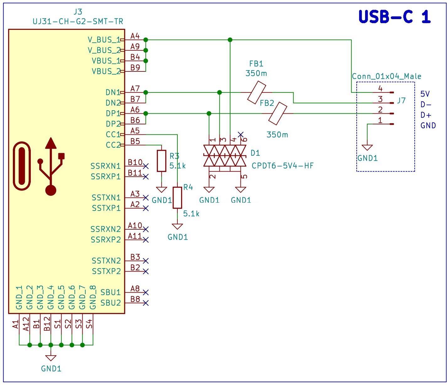
USB C Port and Electromagnetic Compatibility (EMC)
Everything starts with the USB C port, we have chosen this type of USB because it's size and because of the growing trend of using this port to charge and communicate with portable devices.
We have included Transient Voltage Suppression (TVS) diodes and Ferrite Beads to reduce the Electromagnetic Interference (EMI). These protections for the USB port will add compliance with the EMC regulations and standards from the Federal Communications Commission (FCC) and the European Union.
![]()
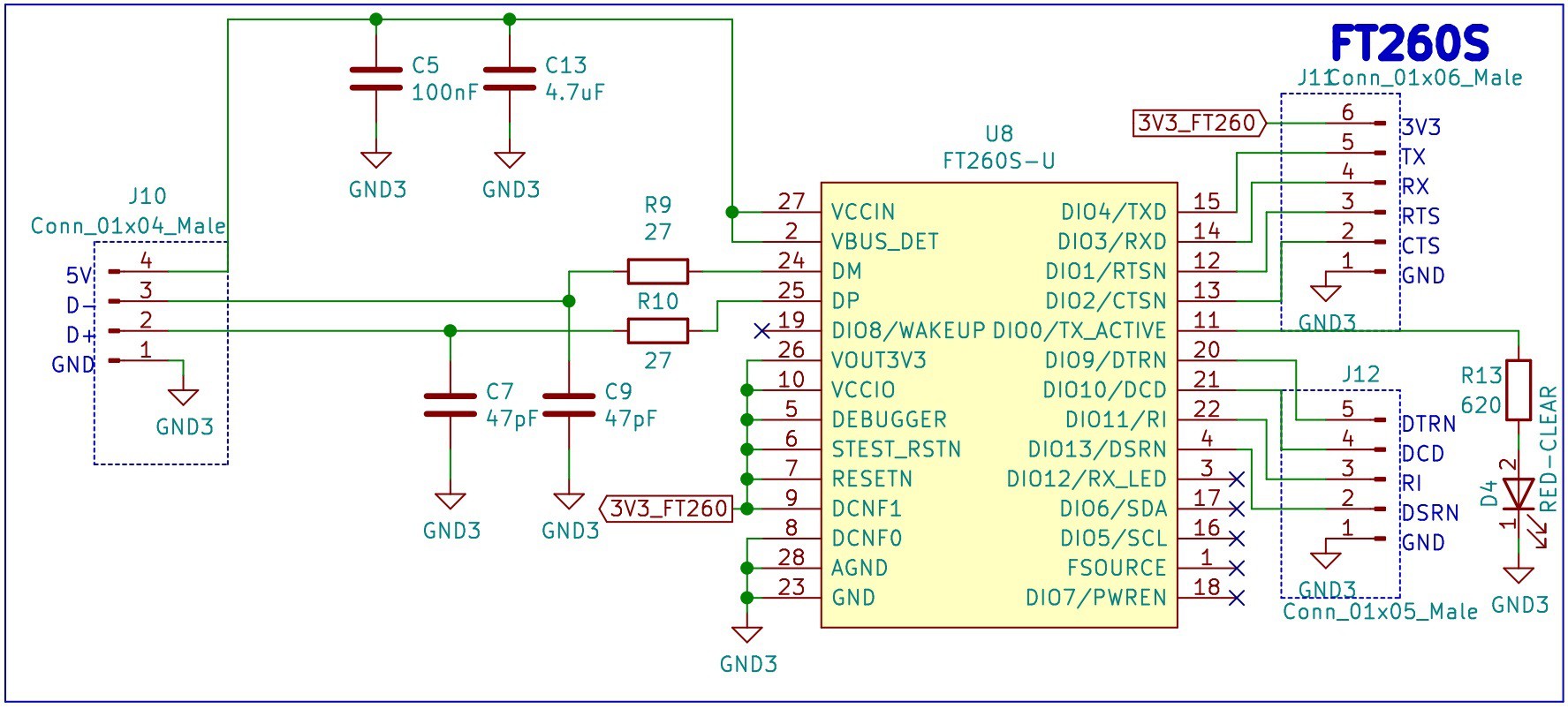
FTDI 1: FT260S-U
The first USB TO UART/I2C FTDI that we want to test is the FT260S-U. In the design we are only considering the USB to UART, therefore the I2C is left unconnected.
![]()
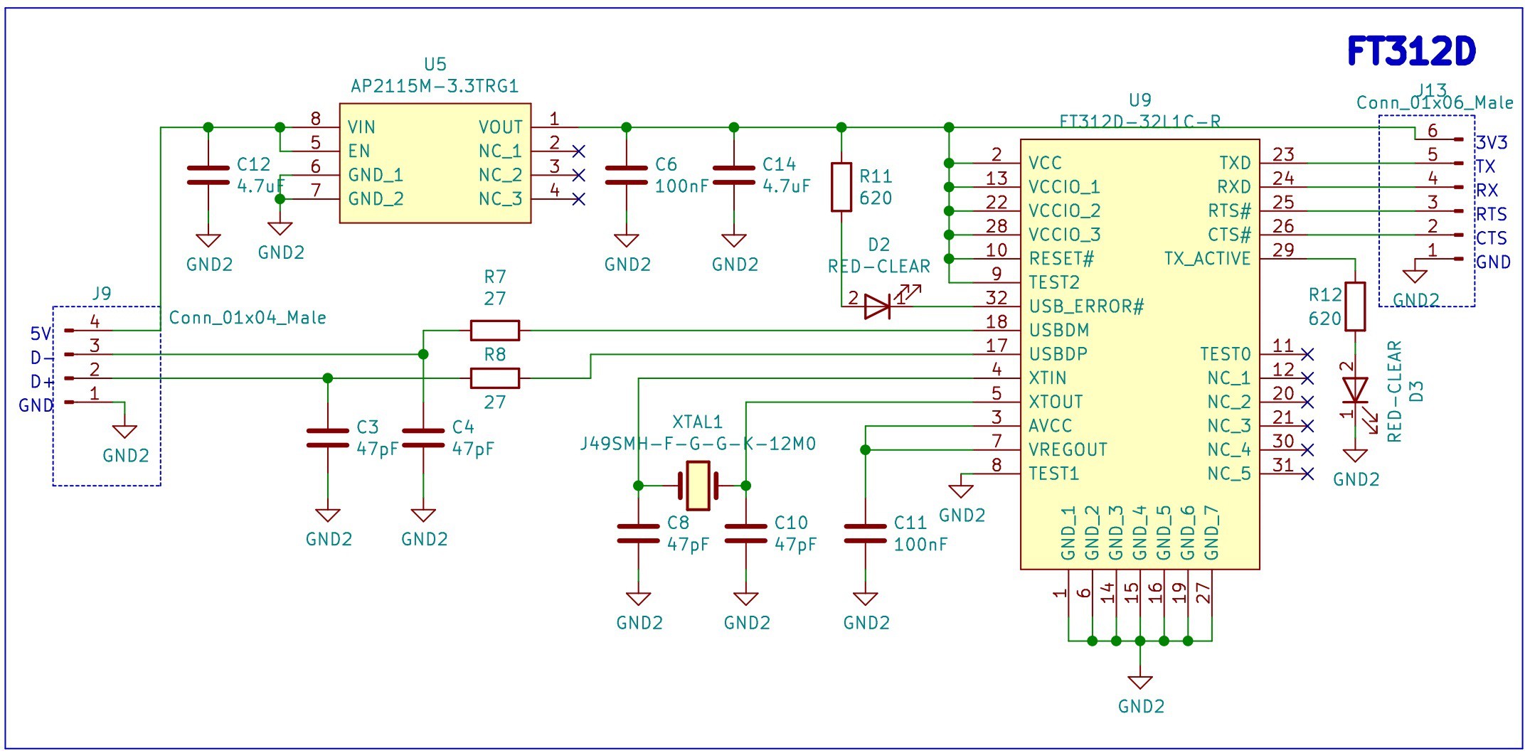
FTDI 2: FT312D-32L1C-R
The second USB TO UART/I2C FTDI that we want to test is the FT312D-32L1C-R. This IC does not support DTR/DSR for the UART, a feature that we require for the auto reset circuit of the ESP32, nevertheless we decided try it as a second alternative.
![]()
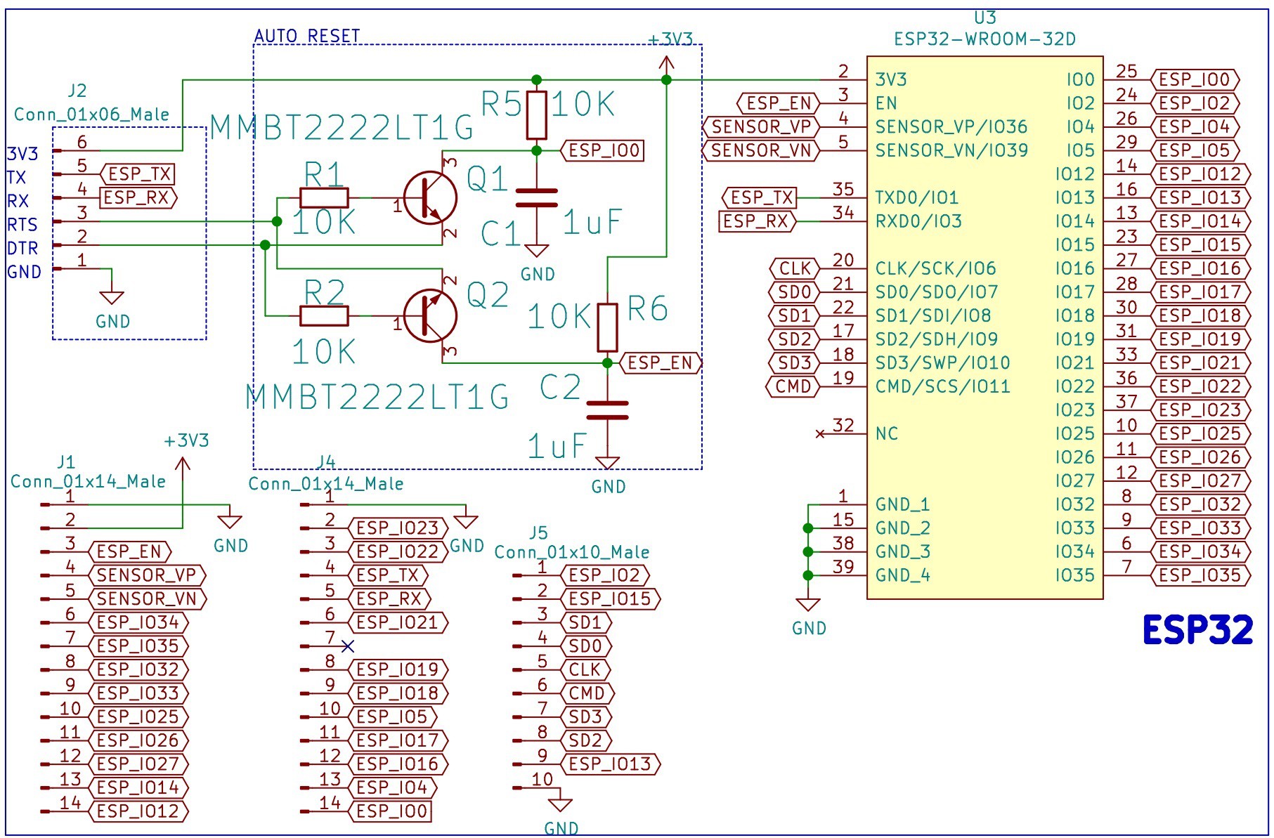
ESP32 with Auto Reset
Finally, we have the ESP32. We have included an auto reset circuit that uses RTS and DTR to reset and put in bootloader mode the ESP32. For more information about this circuit, these blogs [1] [2] can be useful.
![]()
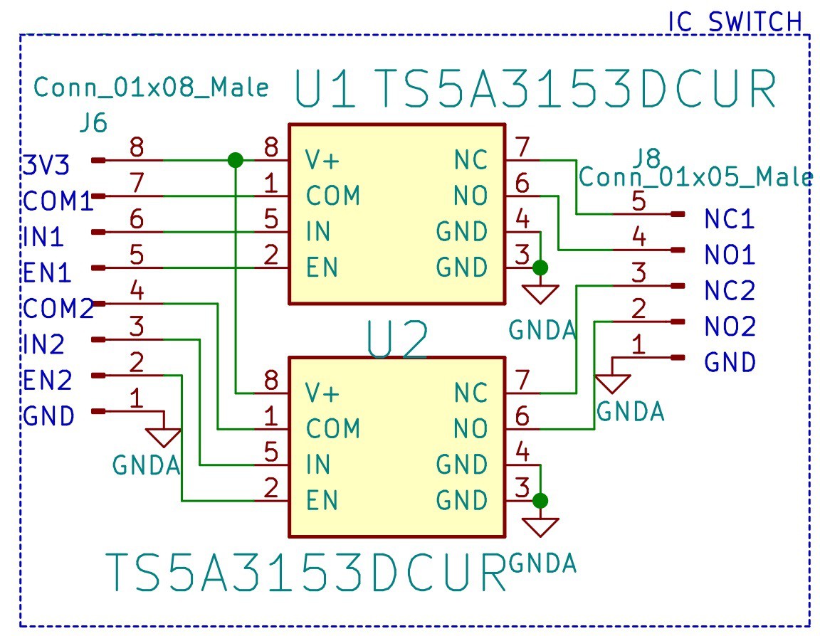
SPDT Switch
In this design we also included a couple of TS5A3153DCUR that we want to test for future implementations.
![]()
Bill of Materials
PCB
![]()
![]()
-
Figuring out MAGNETS!
08/10/2021 at 02:46 • 0 commentsNow that the design for the external and inner wiper are nearing completion, it is time to determine the magnets required for coupling the movement. The unknown that has to be answered is: How many magnets will be needed, and what are their dimensions?
We can narrow down the possibilities with calculations.
Constraints:
- Stick with 1/4" outer diameter / outer size
- N52 is the strongest
- K&J magnetics is less expensive than McMaster-Carr
- Using the standard size servos from Adafruit as a baseline
Servo
Torque
Cost
Torque: At 4.8V: 8.5 kg-cm / 120 oz-in, and at 6V: 10 kg-cm / 140 oz-in.
- 7.3 lb-in
- 8.7 lb-in
$19.95
Torque: At 5V, 5.5kg-cm / 76oz-in, and at 6V 6.5kg-cm / 90oz-in.
- 4.7 lb-in
- 5.6 lb-in
$12.00
Torque means the motor can push X amount force at 1 unit of distance of its lever arm. To find the force, we divide the torque rating by the actual distance of the lever arm.
The servo arm distance with the metal piece is ~35 mm = 1.37 in. For the standard servo at 5V, this means 3.4 lbs of force. Looking at a range of values, if the torque ranges from 4.2 lb-in to 4.7 lb-in, this means the force ranges from 3.0 lbs to 3.4 lbs. Now we can move on to figuring out the magnet portion.
(By the way, in case this is confusing, lbs is an imperial unit of both mass and force.)
The factors for the actual pulling force of the magnets in the wipers are:
- Strength of the magnet
- Gap between the magnet
- Number of magnets
Additional forces acting are the friction between the external wiper and enclosure, and inner wiper and enclosure. Since this is operating under water, there is drag force from the coupled external wiper as well.
The distance between external and internal wiper is 8.4 mm = 0.33 in.
The goal is to have a combined magnet pull force be within the force from the servo’s torque rating. This will need to be verified experimentally.
Using the calculator on K&J magnetics, this determines the pull force between two magnets of the same size given a certain gap distance. The constants will be grade (N52), width (1/4"), and gap (0.33”). This means length, shape, and thickness will change.
Here are the results:
The results for the 0.25” thickness disk are surprising, as these were the magnets used last year and it worked with < 26 magnets.
From the servo calculations earlier, the force is in the range of 3.0 - 3.4 lbs. It would be ideal to achieve this range with ~5 magnets or so. This narrows down the results to the 0.25” thickness block, at 0.5” and 0.75” length.
There is 81.90 mm (3.2 in) to play with on the external wiper magnet holder piece. Both 6x 0.5” length or 3x 0.75” length magnets can fit into.
To verify these results experimentally, we’ll need 12x of the 0.5” magnets, 6x of the 0.75” magnets, and 24x the original disk magnets to serve as a baseline. (It will also be important to not forget that we also need magnets for the servo module before ordering!)
The magnet holder piece for both the external and internal wiper is 3D printed (can be milled during mass production). For adapting to the block magnets instead of disks, dogbones will need to be added to the corners of the pockets. 3D printing will allow for rapid experimentation of combinations of magnets, as well as fine-tuning the alignment in real life.
-
Team EJA Preliminary Presentation
08/10/2021 at 02:32 • 0 commentsWe had our preliminary presentation about EJA the other week as a part of the Hackaday Dream Teams initiative!
We were joined by Clarissa Redwine who is a fellow at NYU and very knowledgeable about design and tech Kickstarter campaigns, as well as Dr. Trippel from the Canada Department of Fisheries and Oceans who has been working with the ropeless fishing gear community, along with Majenta Strongheart and Giovanni Salinas from Supplyframe DesignLab.
During the presentation we cover the differences from v1 to v2, outline the testing considerations, and see a preview of the software. v2 will be released as open source, as was v1. More progress is documented here on our Hackaday.io page.
Through the discussion emerged an interesting point of how we will get this into the hands of fishers. There are advantages and disadvantages to either the Kickstarter or traditional approach. A pertinent example being the possibility of promoting illegal fishing through the accessibility of this device. Perhaps this might be getting ahead of ourselves before completing beta testing with a fisher.
Our next presentation is to be at the end of August. It will be a sprint to the finish line to get this device complete by the deadline!
-
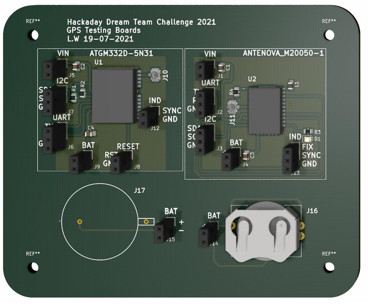
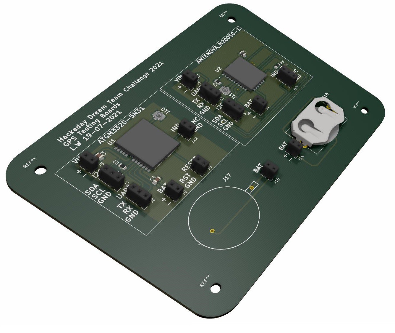
GPS - ANTENOVA M20050-1 and ATGM332D-5N31 Dev Board
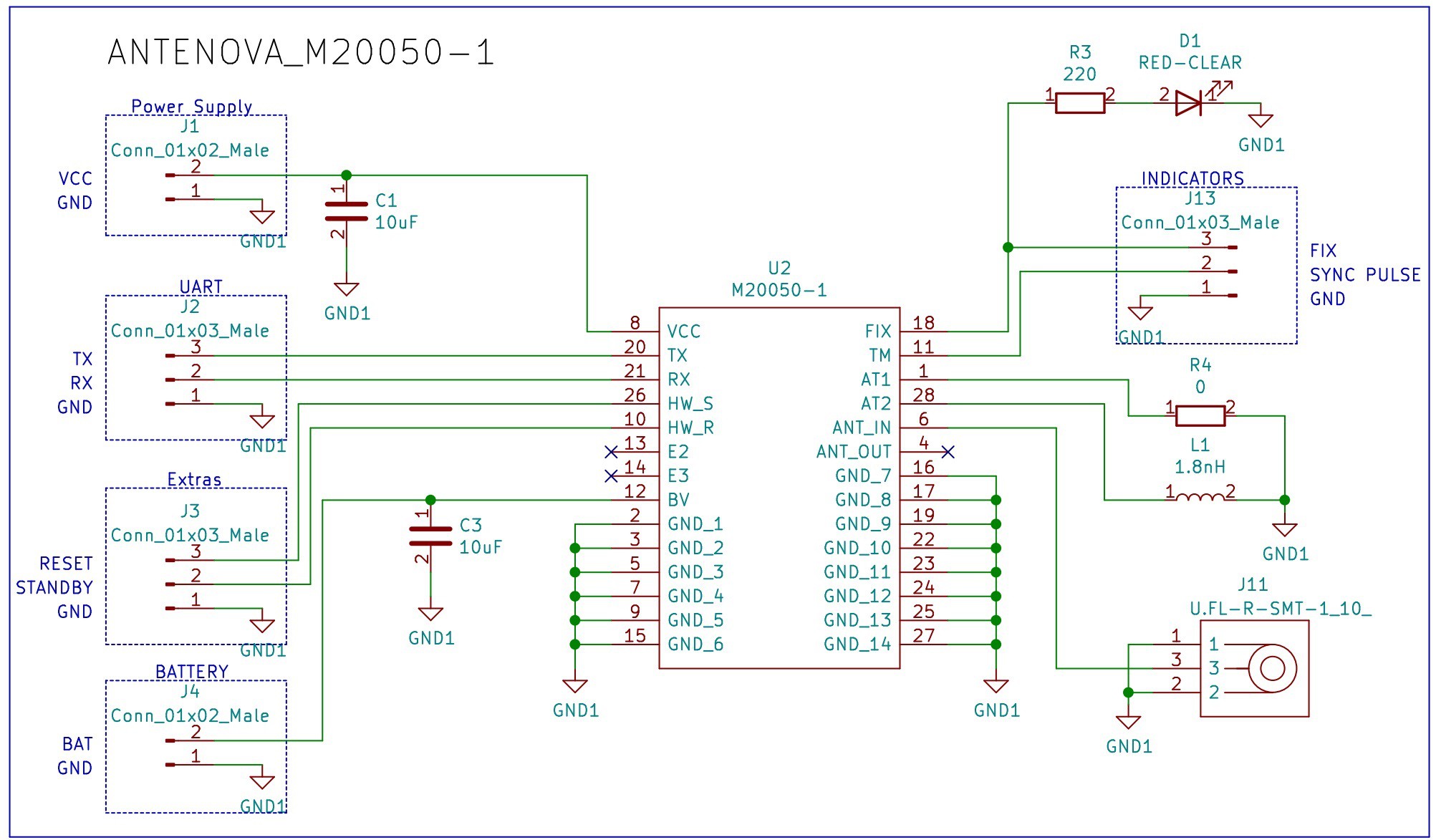
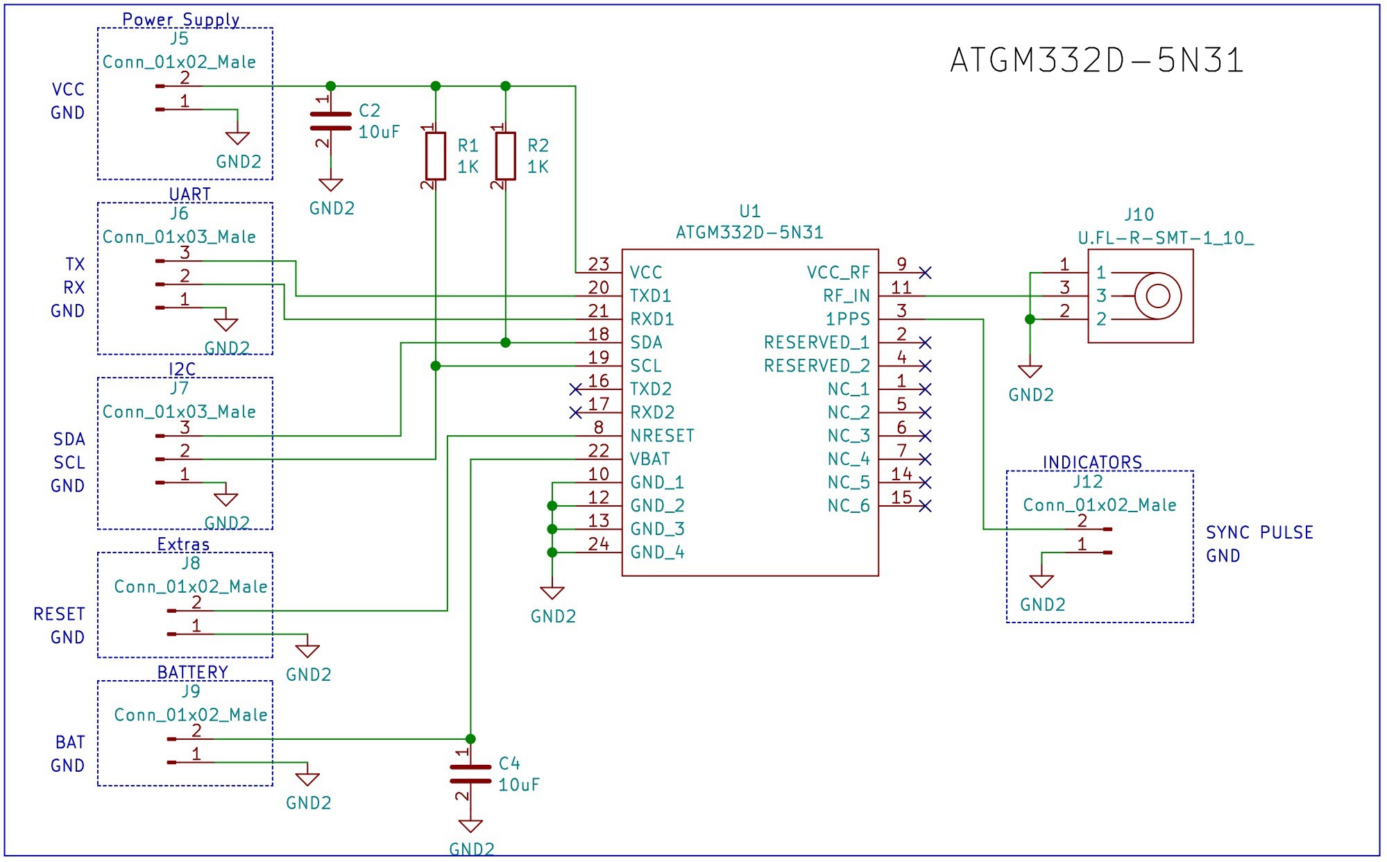
08/06/2021 at 13:40 • 0 commentsSimilar to the development board that we designed to test the RFM95W (LoRa), we designed a new PCB for the ANTENOVA M20050-1 and the ATGM332D-5N31. Those are 2 promising GPS modules that we are considering to replace the module that we used in our previous design, the Adafruit Ultimate GPS.
The schematic is very simple, for each module we included a few decoupling capacitors, a U.FL connector for an external antenna and some headers to have access to different peripherals.
The design can be found in the following Github repository.
Schematic for the ANTENOVA M20050-1
![]()
Schematic for the ATGM332D-5N31
![]()
Also, we are going to test a couple of battery holders.
![]()
Bill of Materials
PCB
![]()
![]()
-
LoRa - RFM95W-915S2 Development Board
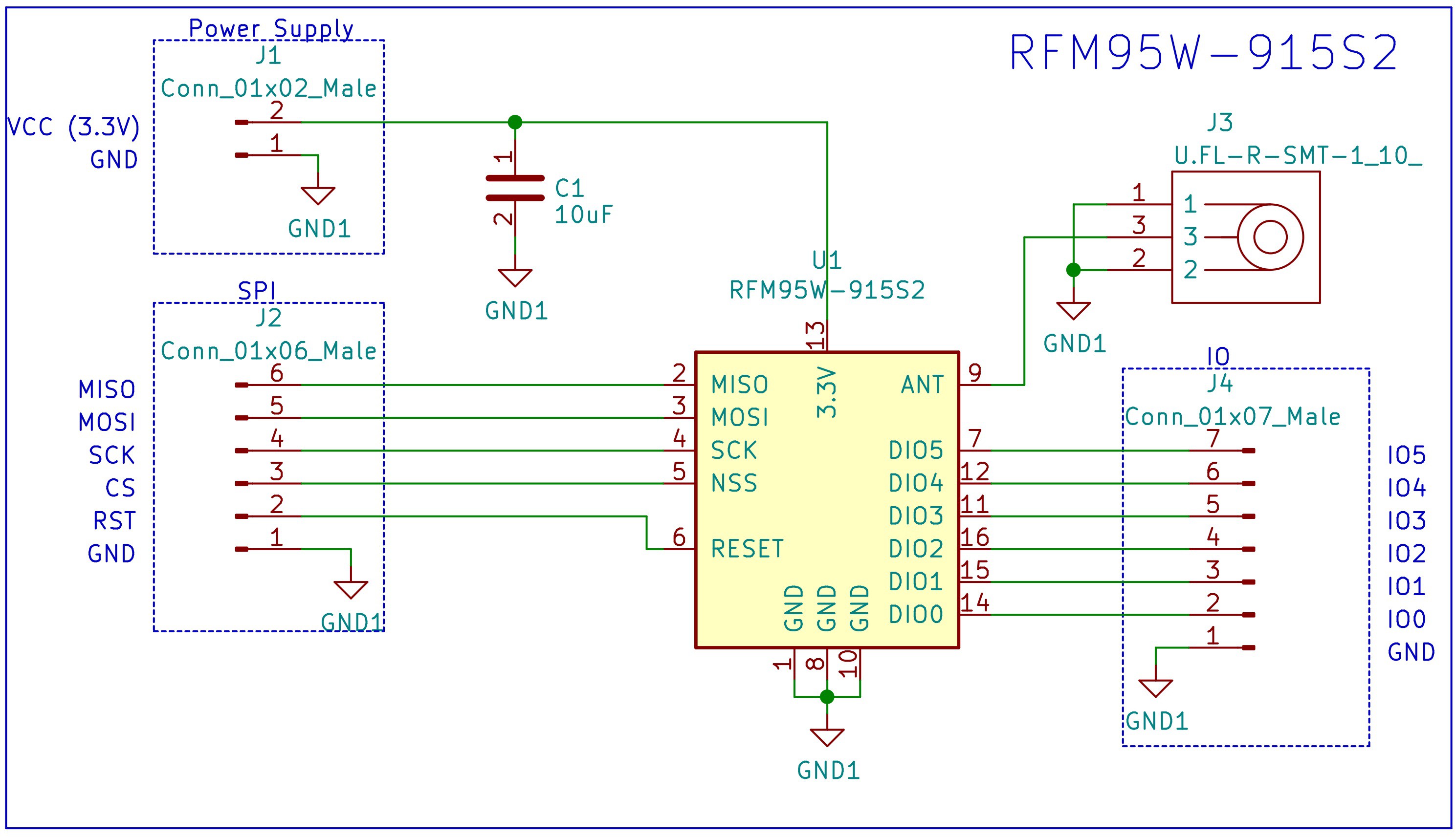
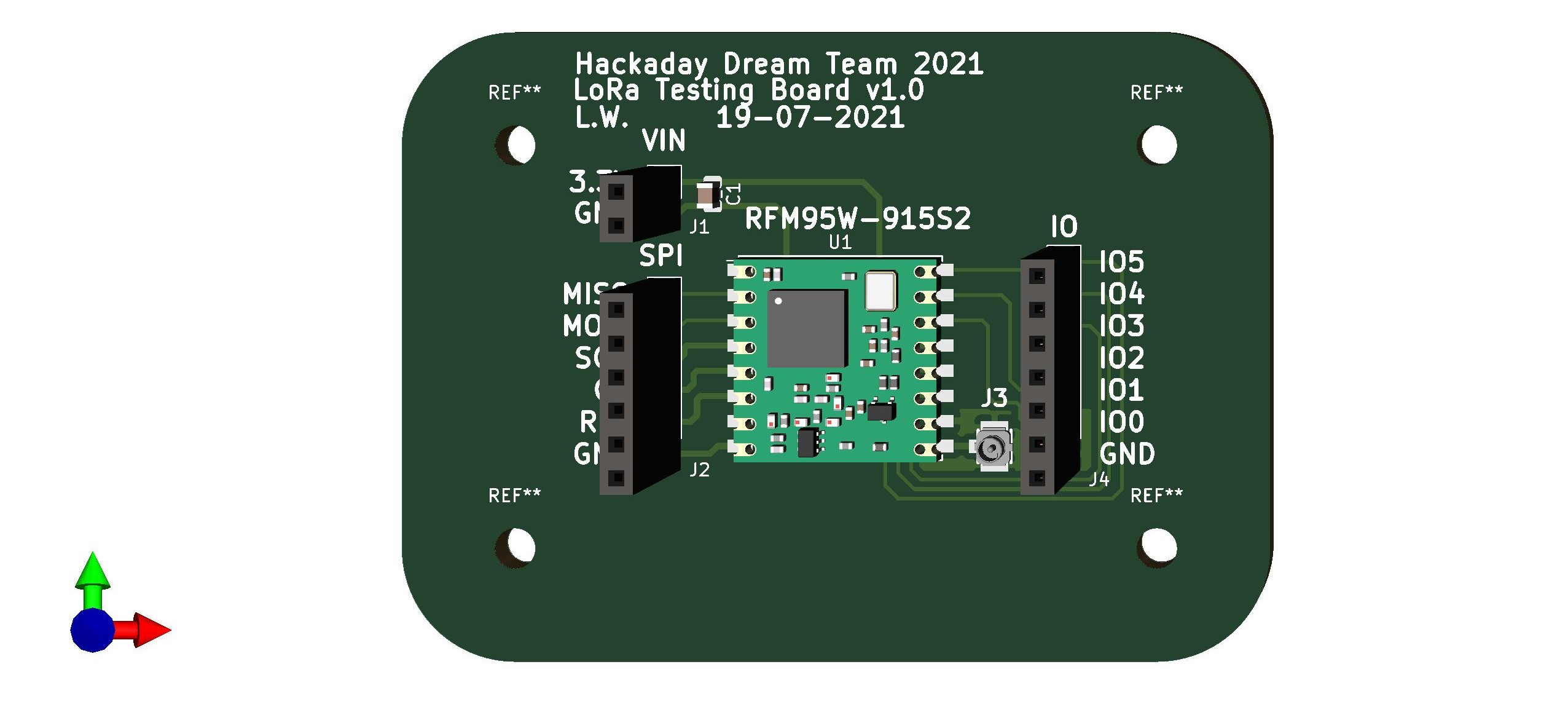
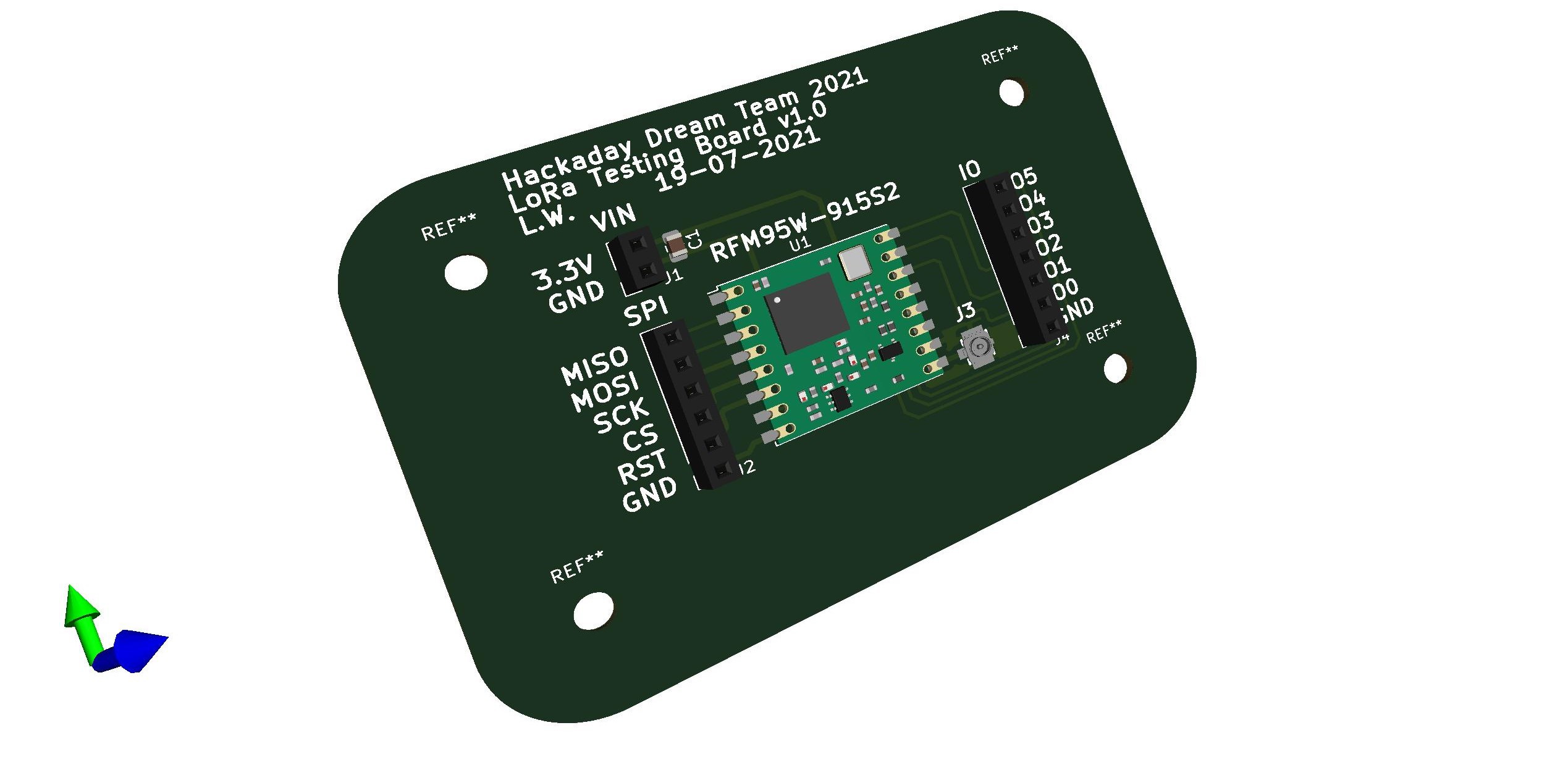
08/02/2021 at 12:39 • 0 commentsBased on the LoRa development board used for the designs Buoy A v1.0, Buoy B v1.0, Onboard Gateway v1.0, we chose the RFM95W-915S2 to implement in the new prototypes.
This post presents the design of our own development board used to test the RFM95W-915S2 before it is included in the final design. The schematic is very simple, it includes a decoupling capacitor, a U.FL connector for an external antenna and a few headers.
The design can be found in the following Github repository.
Schematic
![]()
Bill of Materials
Reference Quantity RFM95W-915S2 LoRa™ Transceiver Module 915MHz SMD 1 10 µF ±10% 6.3V Ceramic Capacitor 0805 1 U.FL (UMCC) Connector Receptacle, Male Pin 50 Ohm SMD 1 Conn Header 40POS 2.54 1 PCB
![]()
![]()
-
System design (LoRa)
07/15/2021 at 13:42 • 0 commentsWelcome back!
Connectivity is a defining attribute of the Internet of Things (IoT). A variety of technologies and techniques allow embedded devices to transmit and receive data. The intersection between connectivity requirements and physical and environmental constraints triggers the use of specific technologies. Low-power wide-area (LPWA) wireless communication technologies such as LoRa and LoRaWAN have shown practicality and ease of use in the field of Internet of Things. The LoRa modulation capability provides a longer communication range, making it an attractive choice in multiple IoT use cases. The energy efficiency and scalability aspects of the LoRaWAN protocol have sparked research curiosity around the challenges and opportunities of using the technology
For the LoRa part of our design, we choose the Adafruit RFM95W radio for both onboard gateway and end node (Bouy A or B)
Some of the high priority goals for implementing our LoRa
• Reduce SW development time in any way possible while maintaining quality.
• Allow for SW modularity and re-usability taking into account possible future developments (For example the possibility of a new HW revision with a change in
MCU or any of the sensors).
• Show the capabilities of the device by building sample applications that show the promise of using a LoRaWAN end device (long-range and low power).
• Adapt with Libraries for Bouy, and onboard gateway communication
• Make the LoRa stay connected for long with continuous ping from the onboard gateway to the bouy.
-
Onboard Gateway 2.0 (New) - From development boards to custom implementations
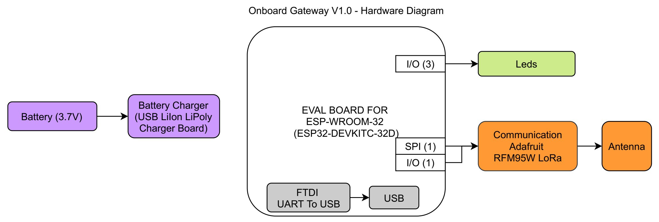
07/13/2021 at 16:24 • 0 commentsSimilar to our previous post that discusses our plans for the Buoy, there is also a plan for the Onboard Gateway. The following image presents the Hardware Block Diagram of the Onboard Gateway V1.0 (our previous design). The different colors are used to group different elements on the design, and facilitate the comparison between different diagrams. The numbers near the peripherals in the microcontroller represent the amount that is being used.
![]()
Design elements:
- Microcontroller (ESP32)
- LoRa Transceiver
- Battery Charger
The previous design used different self-contained development boards to reduce the development time. For the new version we will replace the development boards with the main components in them and place the adapting circuit in our own PCB. Usually a change like the one mentioned reduces the overall price, but not always, it is always important to have the reference price of the development board.
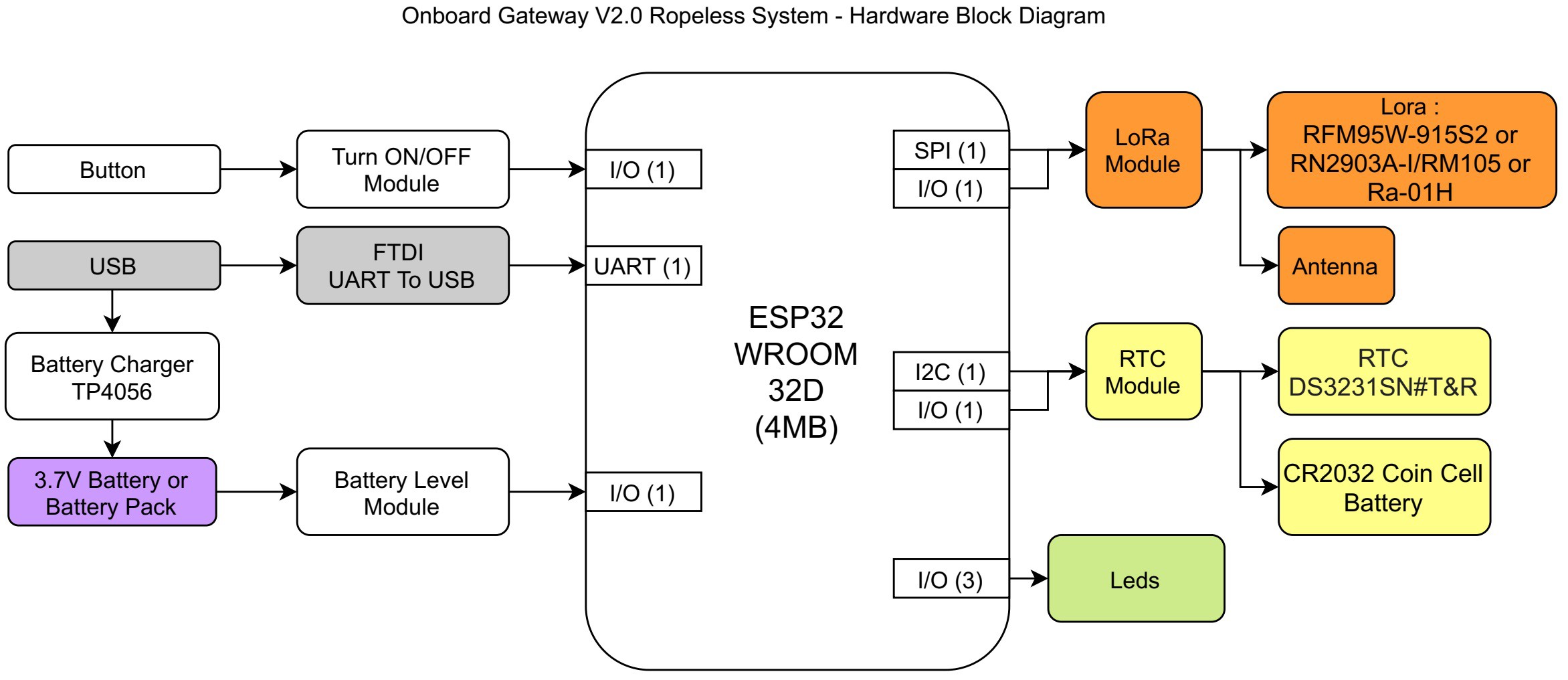
The following image contains the Hardware Diagram for the new Onboard Gateway v2.0, it contains mostly the same basic elements (and therefore features).The most important added feature in the new design is the real time clock (RTC).
![]()
-
2021 - New Objectives for the Electronic Design
07/12/2021 at 20:30 • 1 commentWe have started a new 2 month development cycle! During the first days of the project we went through a planning phase and selected the following goals for this time period. We want to create a Minimum Viable Product that will provide a solution for ropeless fishing.
Our Main objectives in the electronic design are:
- Reduce the cost: We already have developed a few prototypes and we are going to use the Bill of Materials of each one of those designs (Buoy B, Buoy A and Onboard Gateway) as a price reference for future designs. Our last designs cover most of the features that we want on our minimum viable product, therefore the focus is to maintain the features while reducing the cost. To achieve this goal we are going to replace the development modules that we used in previous designs with our own implementation of a circuit that contains the main component (ESP32, LoRa, GPS, RTC and power Supply).
- Include battery charging in the buoy.
- Measure the battery level in all the devices.
- Fix the identified problems from our previous designs.
We also have a few secondary goals that we are going to be exploring. They are not crucial to our minimum viable product, but they will add additional features and expand the scope of our ropless solution. Those objectives are:
- Include data logging (maybe including an SD card)
- Include a Camera
-
Design Decision Matrix
07/12/2021 at 02:57 • 0 commentsWelcome back! The team is back for Dream Teams to develop v2!
This first week was dedicated to planning. We sorted through which functionality is needed for the product, and what would be a nice to have. The timeline is short, we made rough calendars to figure out when the freeze dates are. For example, with design the freeze date and documentation would come before the final test.
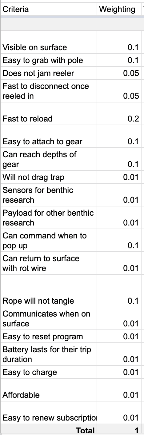
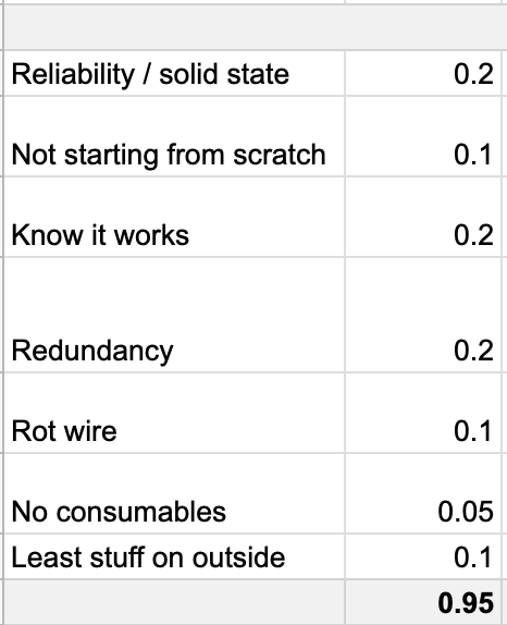
The biggest question for design at the start was if we are going with the same release mechanism. I created a design decision matrix to try to figure this out…….. and it has a lot of criteria! Here’s a preview:
User
Release Mechanism
Buoy
Project
*
* There was a mistake where the buoy category was modified and did not completely add up to 1
Each of these categories were then also placed into a weighted decision matrix. For example, User is weighted the most at 0.4.
Making the final call was tricky, as these numbers are only one data point. After bouncing ideas back and forth with the team and @Giovanni , the final call is to stick with our same release mechanism. We’ll be improving it to make it even better.
The other progress that was made this week here was tidying up a bit for my desk (sounds simple, but it was kind of an undertaking 😳 - there’s a clean surface now to draw on!).
Next log for design will cover some sketches illustrating some of the changes.
-
Buoy B New version 2.0 - From development boards to custom implementations
07/10/2021 at 15:16 • 0 commentsWe are happy to announce that we are working on newer versions for our designs!
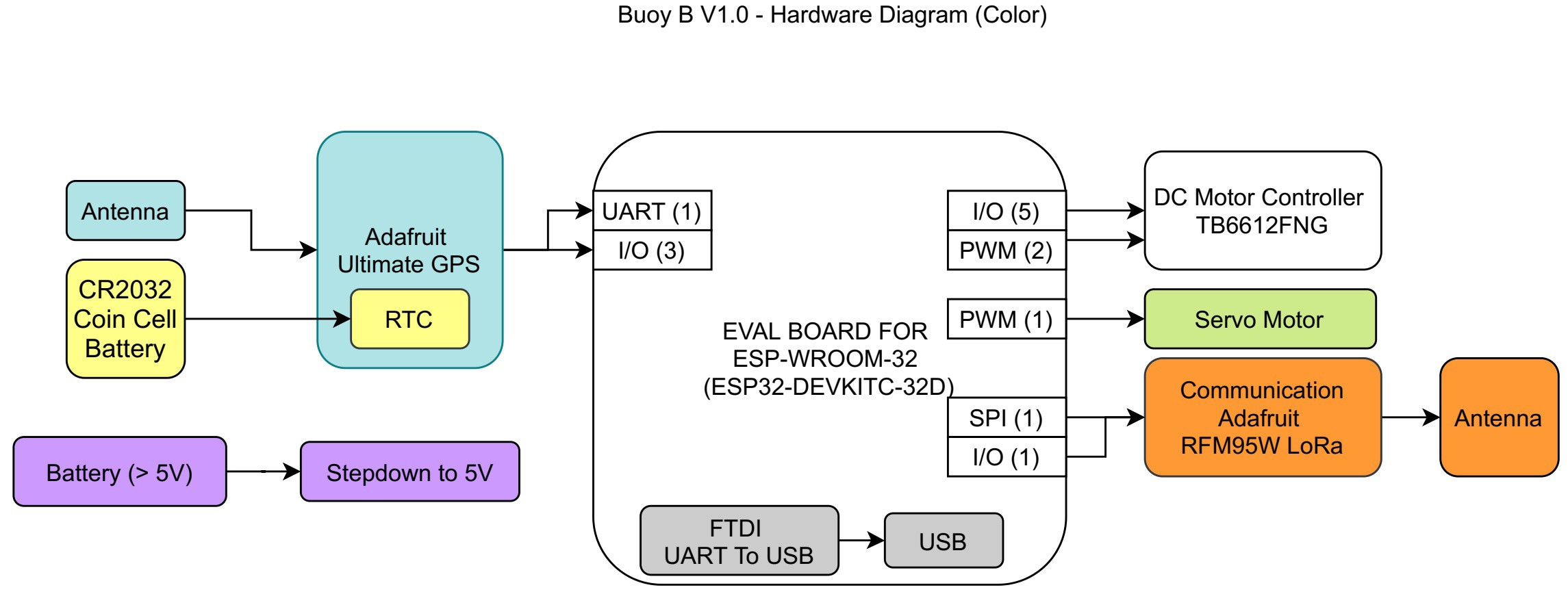
In previous posts we presented the complete Bill Of Materials and the Schematic for the Buoy B v1.0, to create a better representation of the changes that we are going to make and how they align to our goals we created a Hardware Block Diagram for the Buoy B v1.0. The different colors are used to group different elements on the design, and facilitate the comparison between different diagrams.
![]()
Design components:
- Microcontroller (ESP32)
- GPS with RTC
- LoRa Radio
- Power Supply (Battery + DC-DC Buck Converter)
- Servo Motor
- DC Motor Driver
The previous design incorporates different self-contained development boards to reduce the development time.
For the new version of the device we have the goal to reduce the price as much as possible, to achieve that goal we decided to replace the development boards with the main component in them and create the adapting circuit in our PCB. Usually a change like the one mentioned reduces the overall price, but not always, it is always important to have the reference price of the development board.
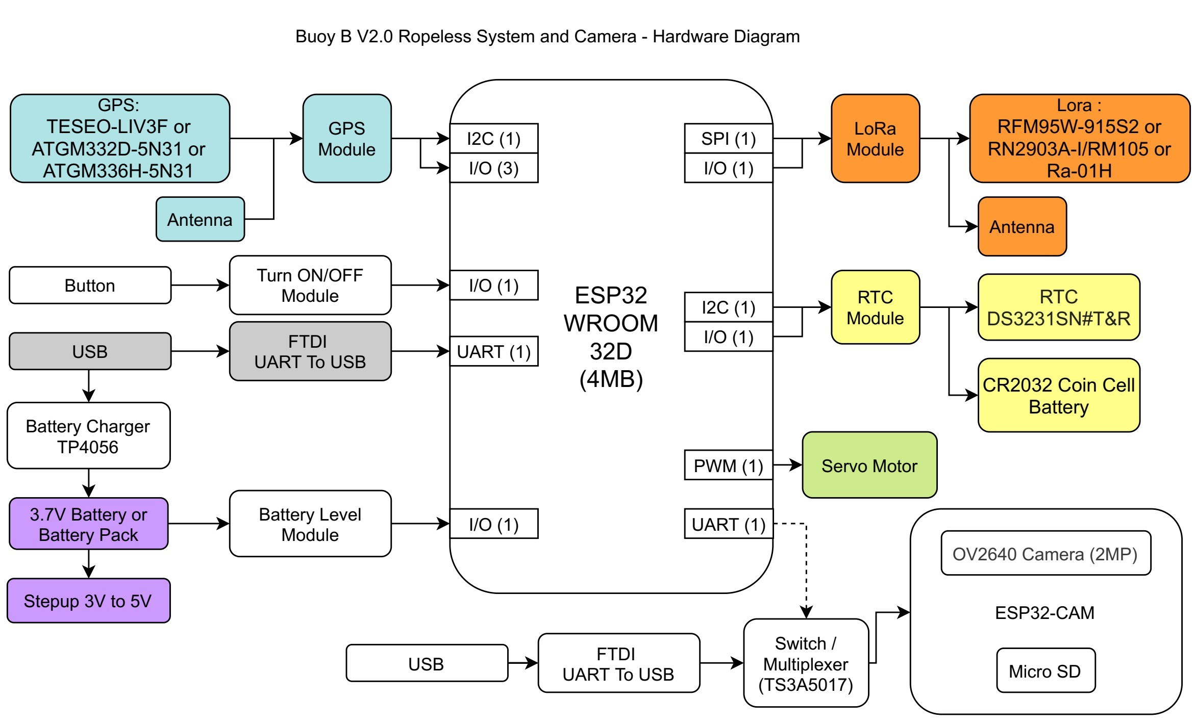
The following image contains the Hardware Diagram for the new Buoy B v2.0, it contains mostly the same basic elements (and therefore features), but there are a few additions like the battery charger and a circuit to measure the battery level.
![]()
The hardware diagram also includes some ideas that we have for future improvements. The ESP32-CAM can add additional features to our ropeless device, like a camera and data logging capabilities. Even though it is not a priority right now, we will have it as an idea to explore in the future after we meet our main goals.
2021 HDP Dream Team: EJA
Learn more about Team EJA's intelligent buoy, and how their solution will help the global fight against ghost gear.