-
1Airframe - Step 1
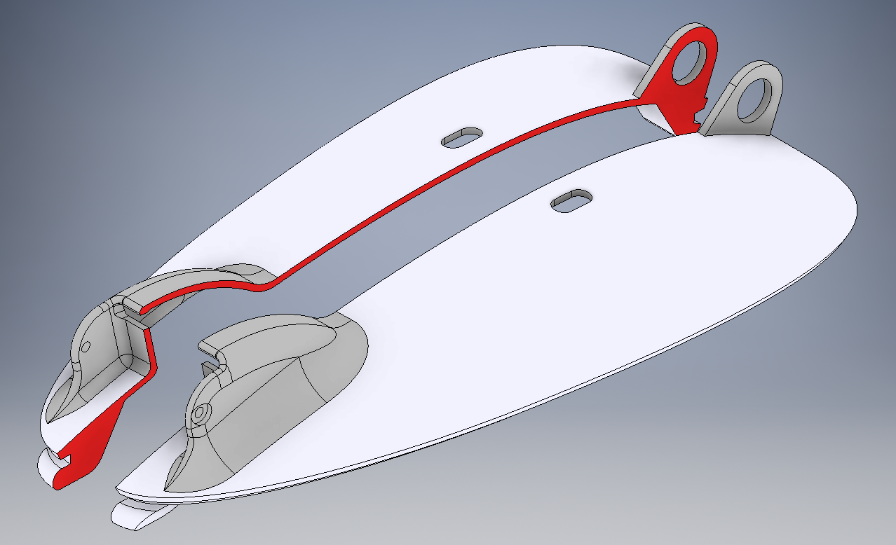
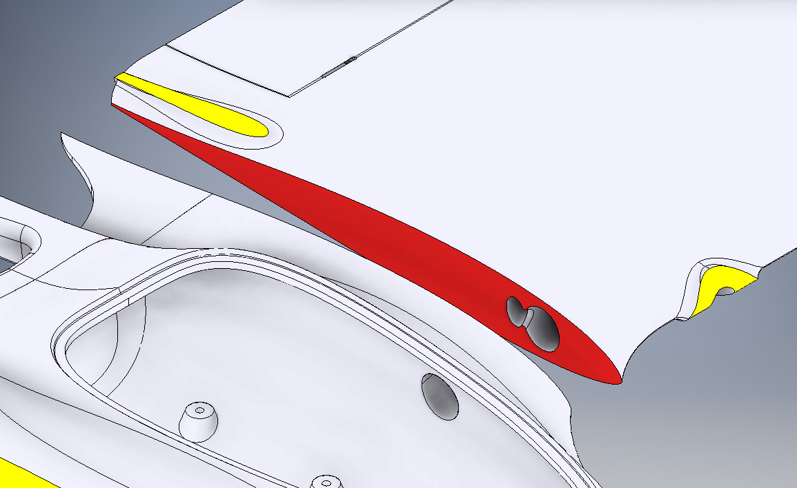
Clean all 3D-Printed parts, remove all brim/support material. For each wing, carefully carve away any stringing or over-extrusion in the hinge reinforcement wells such that the hinge pin will fit.
![Figure 1 Figure 1]()
Hinge Pin Clearance Carefully cut the elevons free if needed (WARNING! Only cut slots on either end to allow for surface deflection, DO NOT cut the entire elevon out), and gently exercise each surface up and down until the living hinge is established.
![Figure 2 Figure 2]()
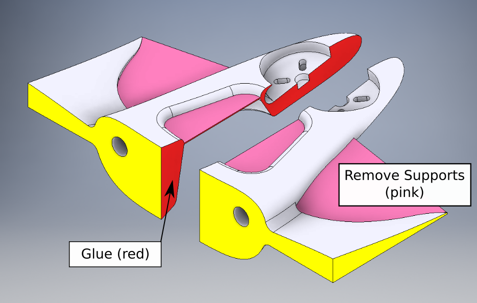
Elevon Movement Cuts Bond the Canopy/Hatch-Lid pieces together using Thin/Medium Cyanoacrylate or Epoxy, and set aside to cure.
![Figure 3 Figure 3]()
Hatch/Lid Bonding -
2Airframe - Step 2
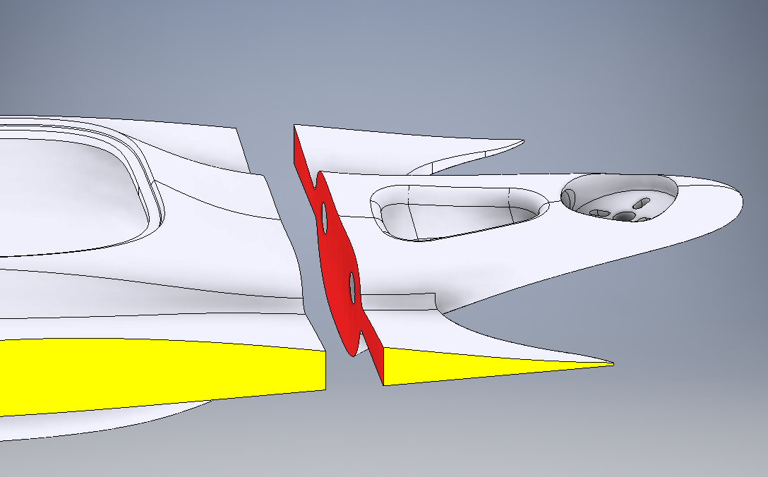
Bond the Empennage Halves together. Thin or Medium Cyanoacrylate, or Epoxy, are acceptable. Set aside to cure.
![Figure 4 Figure 4]()
Empennage Halves Bonding -
3Airframe - Step 3
Bond the Control Horn pieces (2) into each Elevon (Left Wing and Right Wing). Thin or Medium Cyanoacrylate, or Epoxy, are acceptable. The Control Horn should be fairly flush on the Elevon Top Surface, approximately 0.5mm extending above the surface. Fit should be tight; carefully carve away any burrs or over-extrusion from the slot in the elevon if needed.
![Figure 5 Figure 5]()
Elevon Control Horn Install -
4Airframe - Step 4
Glue the Du-Bro Nylon Mini-Hinge pieces (3 per wing, Du-Bro SKU#118) into the recesses along each elevon hinge. Hot-Melt-Adhesive, CA, or Epoxy should work.
Reference: https://www.dubro.com/collections/hinges/products/nylon-hinges?variant=27880366855
-
5Airframe - Step 5
Lightly sand the bonded empennage/tail interface surface until smooth and planar/flush. Test-fit to the Fuselage/Nose to confirm a proper flush joint, and then bond to the Fuselage/Nose using Thin or Medium Cyanoacrylate, or Epoxy. Set aside to cure.
![Figure 6 Figure 6]()
Empennage/Tail Attachment -
6Airframe - Step 6
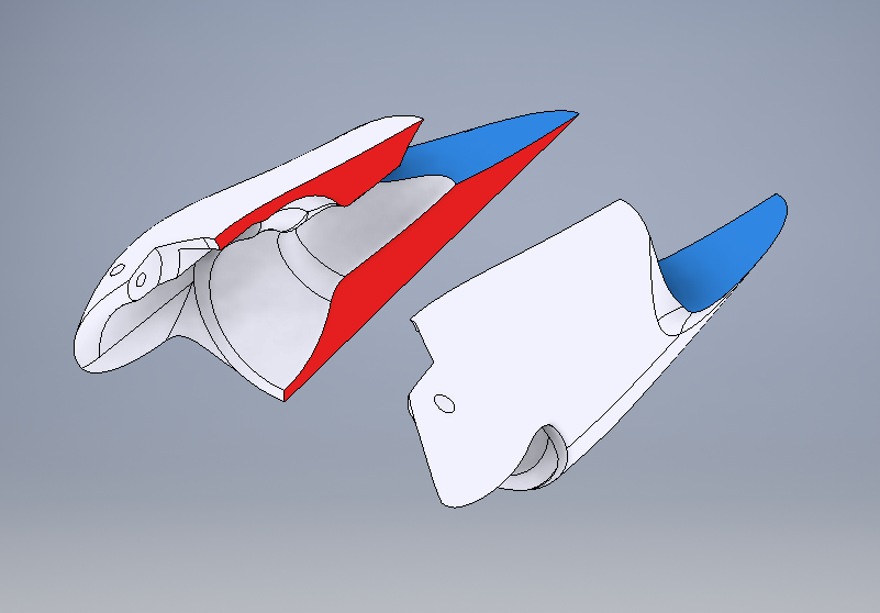
Bond the Nacelle Pair Halves together. Thin or Medium Cyanoacrylate, or Epoxy, are acceptable. Proper alignment is critical, be careful and precise. Set aside to cure.
![Figure 7 Figure 7]()
Nacelle Halves Bonding -
7Airframe - Step 7
Lightly sand both wing root interface surfaces on the completed fuselage/body until flush and smooth. Test-fit both wings to each respective surface to confirm a proper flush joint. Bond either the left or right wing to the fuselage (not recommended to attach both at once) using Epoxy. (Cyanoacrylate may not have the strength needed.) Set aside to cure. When the first wing is cured, bond the second wing and set aside to cure.
![Figure 8 Figure 8]()
Wing Attachment -
8Airframe - Step 8
Test-fit each Motor Mount (Tilt Mount/Pod) with its respective completed nacelle. Sand or trim as needed such that the Motor Mount is able to tilt fully flush forward, and able to tilt up past 90 degrees of rotation.
![Figure 9 Figure 9]()
Nacelle Pocket Finishing -
9Airframe - Step 9
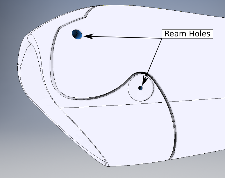
For each Nacelle with its respective Motor Mount aligned and present, Ream (Drill to size) using a 1.58mm (1/16 Inch, 62.5mil) drill bit. (Should be 85% to 90% of diameter of hinge rod to be fitted. Hinge Rod diameter is 1.84mm or 72mil for this case.) Keep the Motor Mount and Nacelle together. Adapt a section of hinge rod to be used as a final precision reaming tool by sharpening the tip using a grinder or emery wheel. Use this improvised reaming tool to ream the hole in each nacelle-mount pair to the final diameter of 1.84mm (72mil).
![Figure 10 Figure 10]()
Shaft and Bolt Hole Reaming -
10Airframe - Step 10
Remove each Motor Mount from its respective Nacelle and ream only the Motor Mount hole to the next higher drill bit size, not to exceed 107% of diameter of the the hinge rod. Too large will allow for excessive play and possible rattling; too small will result in binding. 1.95mm (77mil, 5/64 Inch) is acceptable for hinge rod diameter of 1.84mm.
MiniHawk VTOL
A fully 3D-Printable VTOL aircraft, designed as a hybrid fixed-wing plank + tricopter planform. For FPV and UAV experimentation.
 Steve Carlson



Discussions
Become a Hackaday.io Member
Create an account to leave a comment. Already have an account? Log In.