-
11Airframe - Step 11
Cut the hinge rod pieces, not to exceed 24mm length. Roughen/knurl one or both ends if desired. Press-fit each hinge rod to each Nacelle through the respective Motor Mount. Verify that each Motor Mount can rotate freely and with minimal play in the hinge.
-
12Airframe - Step 12
For each Motor Mount, ream the Motor Mount linkage mount hole to 1.19mm (3/64 Inch, 47mil). This should be about 80% of the major diameter of the threaded ball link to be mounted. (Great Planes Threaded Ball Link Set 1/16", GPMQ3843; ball-link is 1.50mm major diameter.) Mount the threaded ball-link to the linkage mount hole. The Motor Mount can sustain up to 3.3mm threaded bolt depth, verify that the bolt does not extend too far into the well, such that it will not make contact with the motor.
For Reference: https://www.towerhobbies.com/product/threaded-ball-link-set-116-6/GPMQ3843.html
-
13Airframe - Step 13
Bond each Nacelle to its respective wing; note that the ball-link should align with the respective servo linkage slot/well. Epoxy is recommended, as this is a significant load-bearing structure. Verify alignment and tweak/tune while the glue cures.
![Figure 11 Figure 11]()
Nacelle Attachment -
14Airframe - Step 14
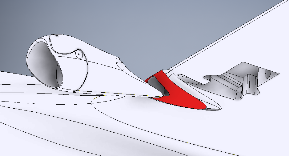
Bond both vertical fins to the wing(s).
![Figure 12 Figure 12]()
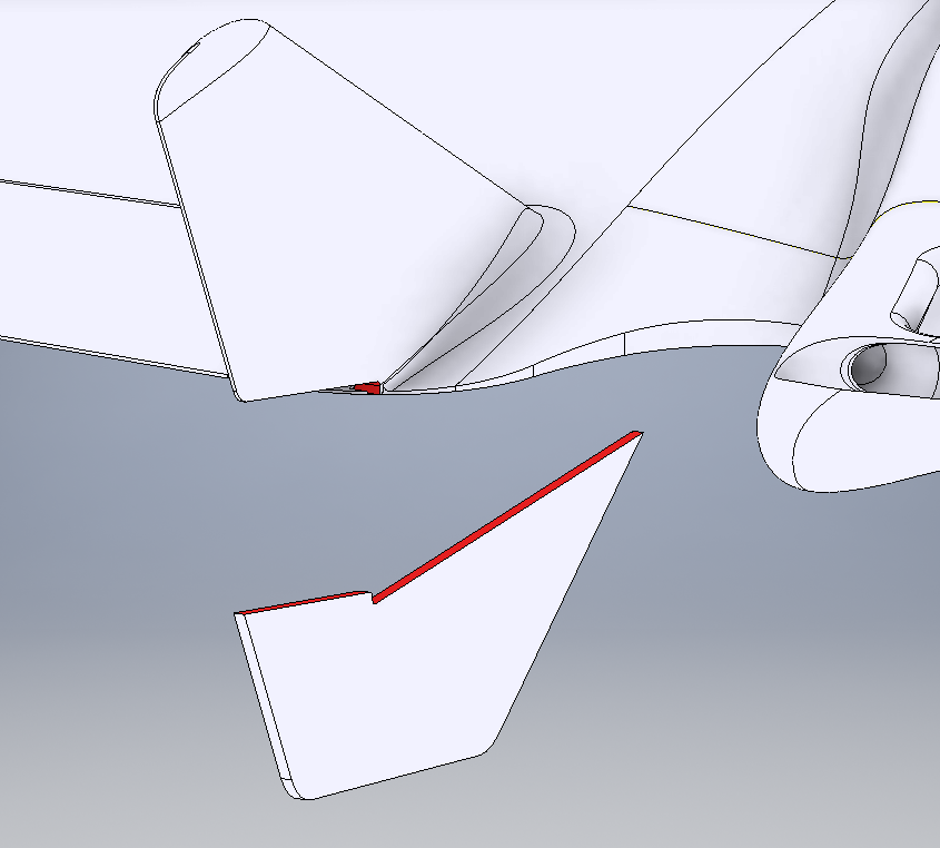
Vertical Stabilizer Attachment Medium Cyanoacrylate should be sufficient. Bond the Rear Strakes to the bottom of the wing(s) and bottom edge of the vertical fins.
![Figure 13 Figure 13]()
Strake Attachment -
15Linkages/Components - Step 1
Mount the front two motors in their respective Motor Mounts. The motor leads may have heatshrink that may interfere or bind the wires; rework this if needed. Mount the motors using the M2 threaded bolt kit that should be included with each motor. Be careful not to have any mounting bolt over-extend into the motor armature/stator. Verify that each motor turns freely and is well secured. Route the wires through the wing and into the main bay, and test the extension-retraction behavior of the wires as the motor mount pitches between forward and hover tilt positions. For each motor, attach the propeller hub hardware kit that should be included with each, such that it can drive a standard 5-Inch propeller.
-
16Linkages/Components - Step 2
The Rear motor should mount to the tail using M3 threaded bolts that were included with the motor. Route the motors wires through either wire duct channel to the main bay as desired. Verify that the motor rotates freely and is well secured. Attach the propeller hub hardware kit that should be included with the motor, such that it can drive a standard 5-Inch propeller.
-
17Linkages/Components - Step 3
The Motor Mount Tilt servos should be tested and centered on a standard RC PWM signal, visiting 1000us, 1500us, and 2000us pulse-widths. Attach a servo arm with a 19.3mm (0.76 Inch) hole-to-center spacing. This value is critical, as the linkage behavior of the tilting front motor mounts cannot be easily modified and any length short of this will result in the motor tilt not reaching the needed angle for hover and anti-torque (yaw) control. An arm any longer than this will not fit in the linkage well/slot. With whatever arm fitted as similar to 19.3mm as possible, test fit the servo into the servo well and verify that between 1000us and 2000us pulse widths, the arm comfortably retracts into the well/slot, and fully sweeps about 90 to 95 degrees from that point. Verify the best servo arm spline position and bolt/secure the arm in place.
![Figure 14 Figure 14]()
Linkages and Movements -
18Linkages/Components - Step 4
For each of the Elevon servos, repeat the same procedure as above, but with a servo arm approximately 9.5mm hole-to-center (3/8 Inch). This length can be a bit longer or shorter, the effect is increasing or decreasing elevon control throw. For servos that have an odd-number spline tooth count (such as the Hitec HS-65HB's B1 spline with 25 teeth), to get the most well-centered and symmetric solution, center the servo on a 1500us pulse width and alternate attaching a 4-arm output horn between each 90-degree position to find the most orthogonal/centered position, and then cut off the 3 unneeded arms.
-
19Linkages/Components - Step 5
Verify that the Link Clevises that attach to the servo arms are able to couple and rotate freely. Reaming each servo arm may be necessary, a value of 1.59mm (1/16 Inch, 62mil) is common.
-
20Linkages/Components - Step 6
Route the servo wires through the conduit tunnels in the wing to the main bay. Be advised that this is somewhat irreversible, depending on the quality of the 3D print, any glue protrusions in the tunnel, and weaving/tangling of the pigtails after routing. The pins in the 3-pin header on the pigtail can be carefully removed to allow the wires to pass back out if needed later. Assuming all servos have a 6-inch (~150mm) pigtail, the Elevon servos will have some slack, but the Tilt servos will arrive just barely at the main bay. Servo Extensions can be added, or the servo pigtail can be extended with a section of 3-wire servo lead/cable, or the 3-pin servo connectors can be discarded in favor of direct soldering later if desired.
MiniHawk VTOL
A fully 3D-Printable VTOL aircraft, designed as a hybrid fixed-wing plank + tricopter planform. For FPV and UAV experimentation.
 Steve Carlson


Discussions
Become a Hackaday.io Member
Create an account to leave a comment. Already have an account? Log In.