 Ken Yap
This is a clock board designed to mate with the 6-segment or 7-segment display boards that I previously published. It interfaces to a DS3231 module for accurate timekeeping. The design is conventional. As there is plenty of room on the board, it supports options, annotated in the schematic. That's why it's not fully populated. The firmware is at Github, see the links.
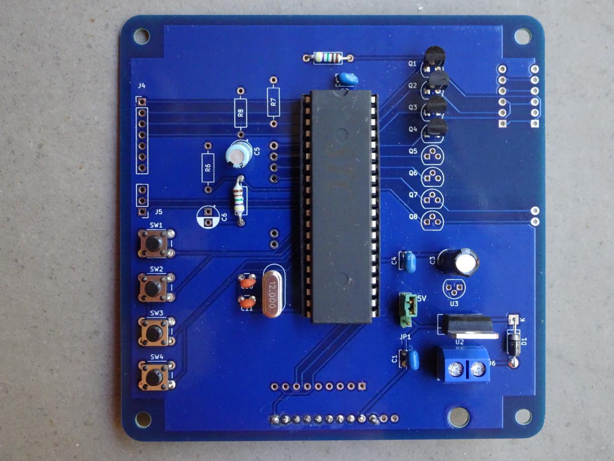
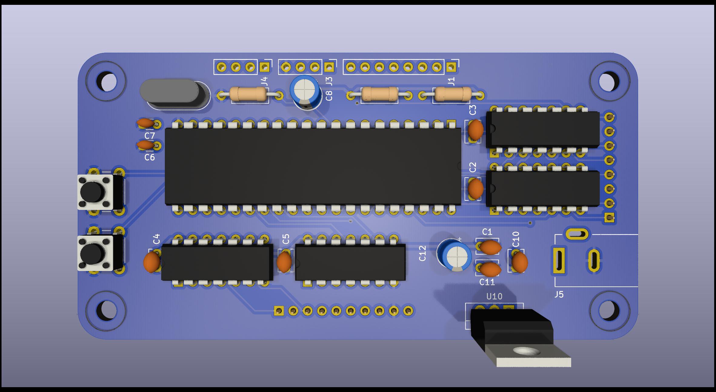
I managed to get a professional STC89C52 MCU to pose for this picture instead of the WFH model shown in the virtual 3D rendering. Also the PCB insisted on coming dressed in blue soldermask so I had to indulge it a bit. 🤣
Time passes. I was forced to take a many-month break due to renovations on my home. Finally I got around to installing the missing connector and plugging in a test 4 digit display board. You can see the result in the gallery. Sorry for the fisheye distortion, I used my phone camera. I really need to set up a proper photographing environment for my projects. You can see the RTC in one photo. The firmware was tweaked a little, you can see the details in the Github repo but no substantial changes as testing had already been done with the QX-mini51 development board. Now I can finally mark this project completed. I'll probably couple it to the 6-segment display that I built in #6 segments suffice and give it to a friend as a novel memento.
I've added a couple of photos to the gallery of the clock board piggybacked onto the 6-segment display. You may notice that the 0 is not the same as in my project #6 segments suffice . I'm experimenting with using the upper loop as a 0, but it's compromised by the gap in the middle most clearly exhibited by the 5.
Update, 2025-02-15: I still have a few unpopulated boards and looking at them I realised that I disliked many things about that design. Among them:
- It's designed to take 12V from a wall wart but I've used Bornier connectors. I could use a barrel socket and not have to cut off the barrel jack from the cord.
- Since all 12V barrel jacks that I know of are centre positive, I don't need the reverse polarity protection diode.
- I don't need to cater for both the TO-220 and the TO-92 package variants of the LM7805 linear regulator since I have a pile of the larger, but none of the smaller package now and don't intend to buy any.
- I don't need 4 tactile switches, I can get by with 2 with my now polished mode/increment UI button scheme.
- I can incorporate the cathode drivers on board. Unfortunately the STC89C52 doesn't have push-pull outputs, only the old weak pullup of the original 8051. By using cathode drivers, I don't need the pullup resistor network.
- Similarly I can substitute driver ICs for the high side anode digit driver transistors. All 8 bits of the port can be used instead of 6.
- The DS3231 RTC module, if used, can be connected by leads to other port pins. I2C is handled by bit banging, as the STC89C52 has no hardware I2C support.
- I don't need to cater for both polarities of the reset line since I only have one AT90S8515 AVR MCU.
- I don't need to make the board in 100x100 mm form factor if I give up the anode drive connectors. These can be flying leads anyway, only one is needed per digit which doesn't warrant daisy-chained connections.
So I designed a second version of the board which is 100 mm wide but only half as tall with a more compact layout. I ordered 5 boards which should exhaust my old-fangled STC89C52 stock. It uses ancient-fangled TTL 7406 and 7407 open collector drivers. I make no apology for them as they are what I have on hand.

I doubt if anybody is interested in this design, but if you are because you have some 8051 descendant to use, there are probably better driver chips that can interface to the multiplexed LEDs. Or not multiplex the LEDs and use power shift registers. I'm eyeing LED filaments for large digits. They take quite a bit of current to drive.

 Michael O'Brien
 Enzo Lombardi
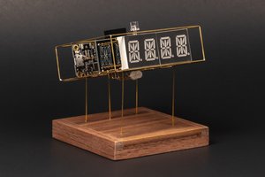
 romaindurocher
 kwan3217