Wissam Tedros
-
PCB
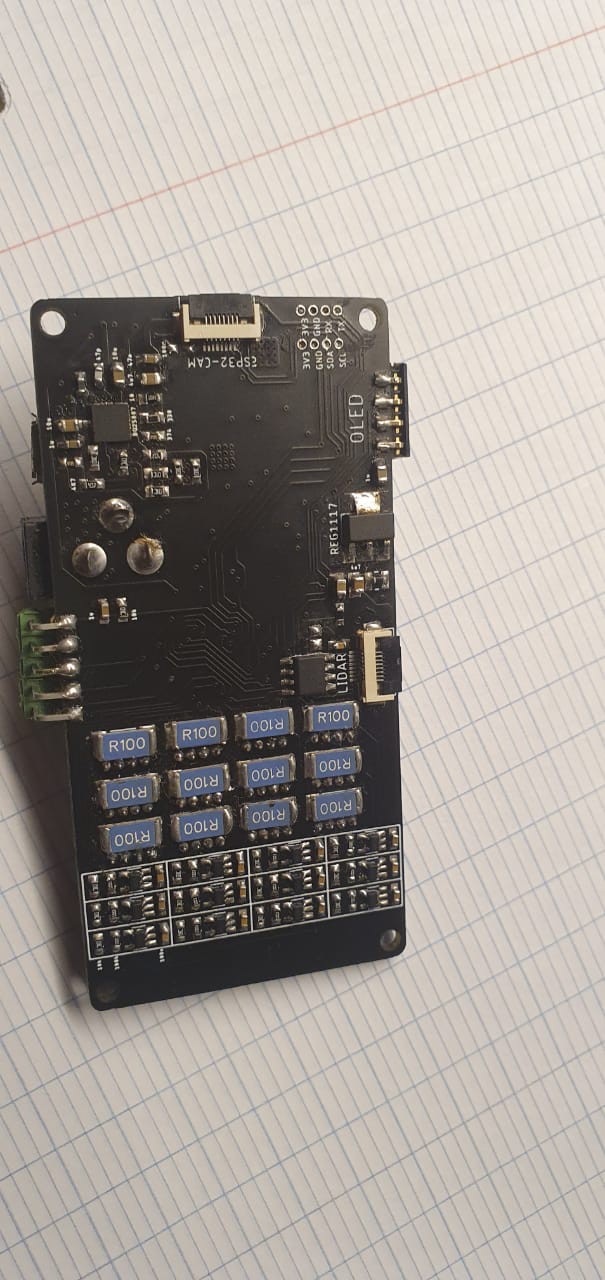
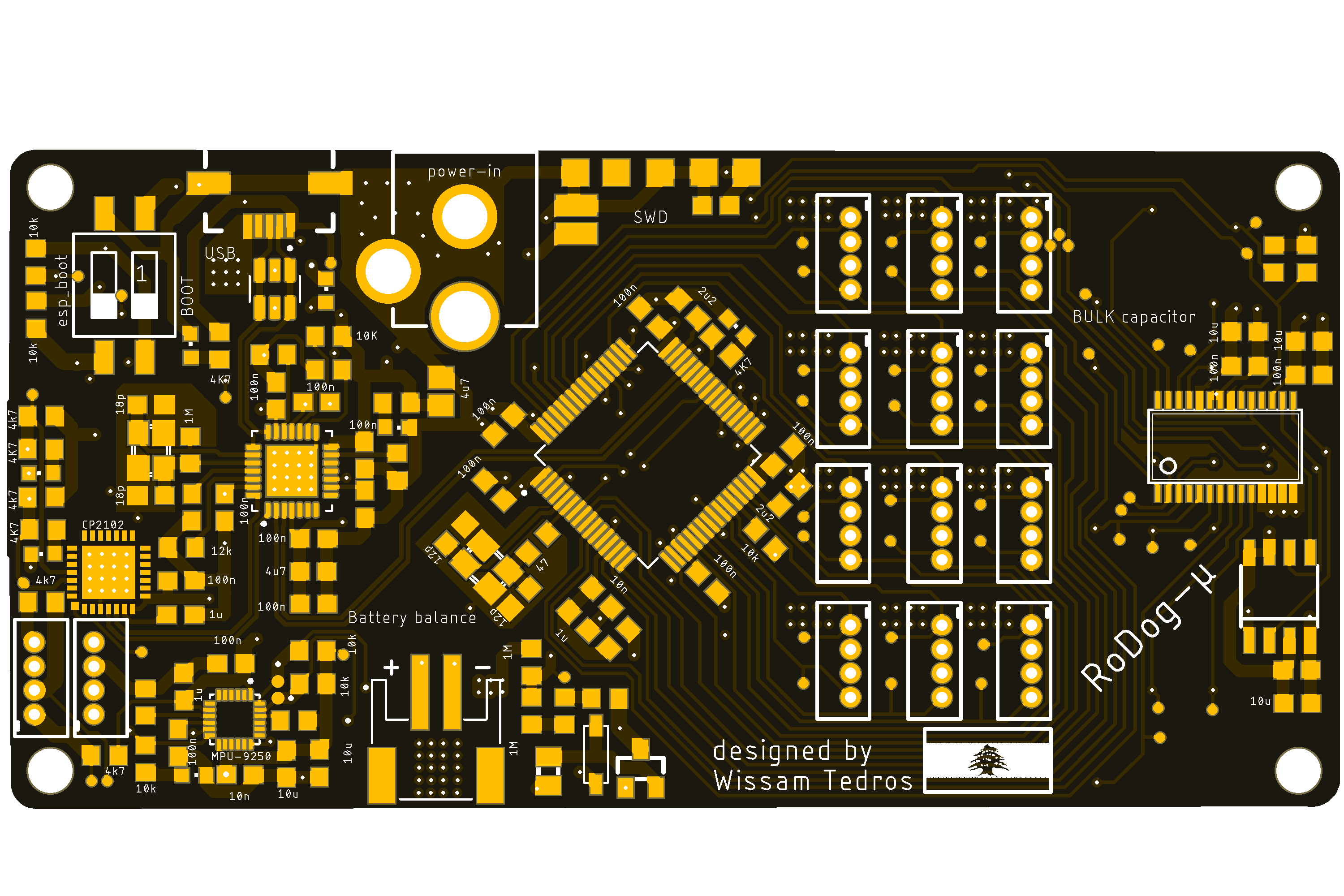
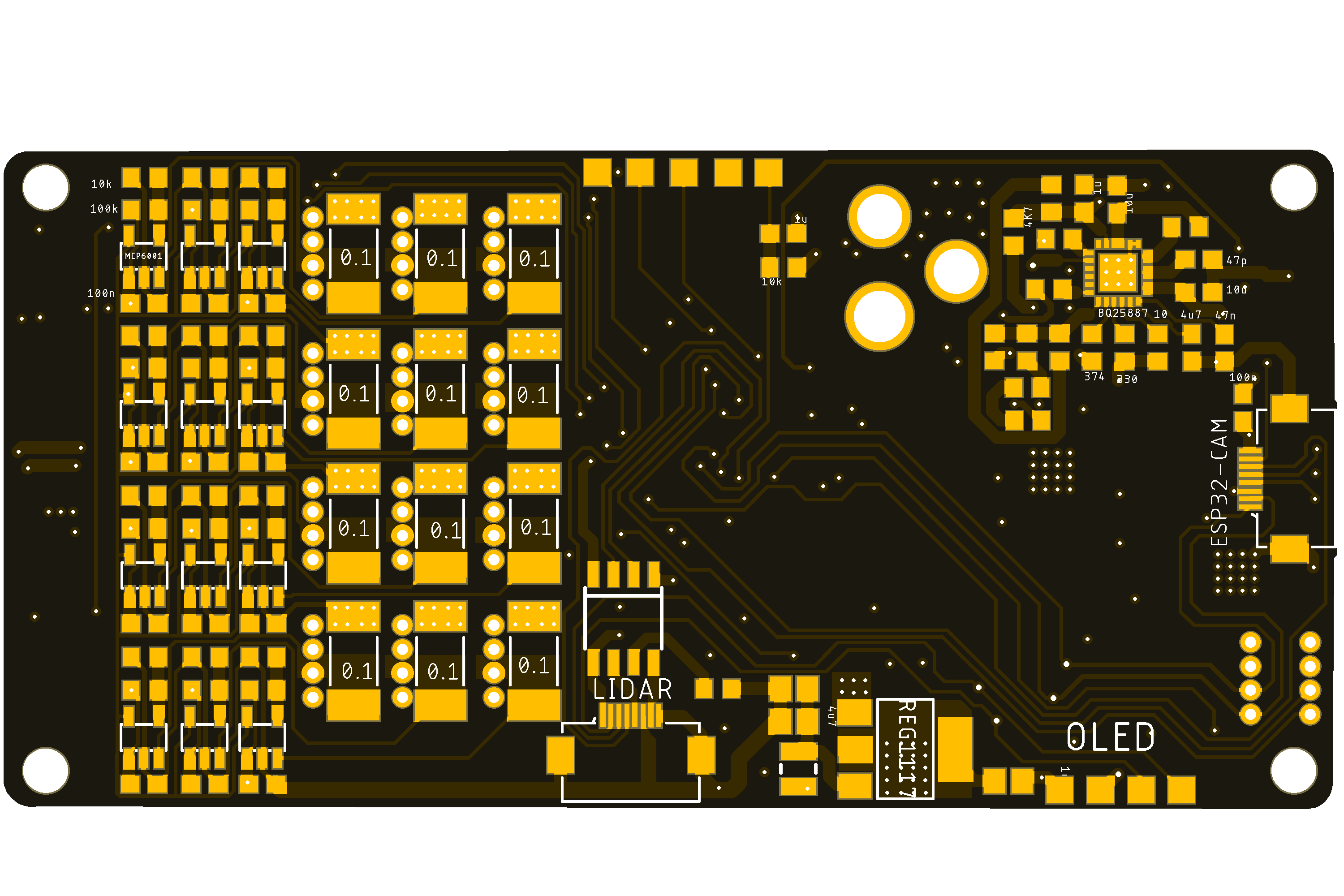
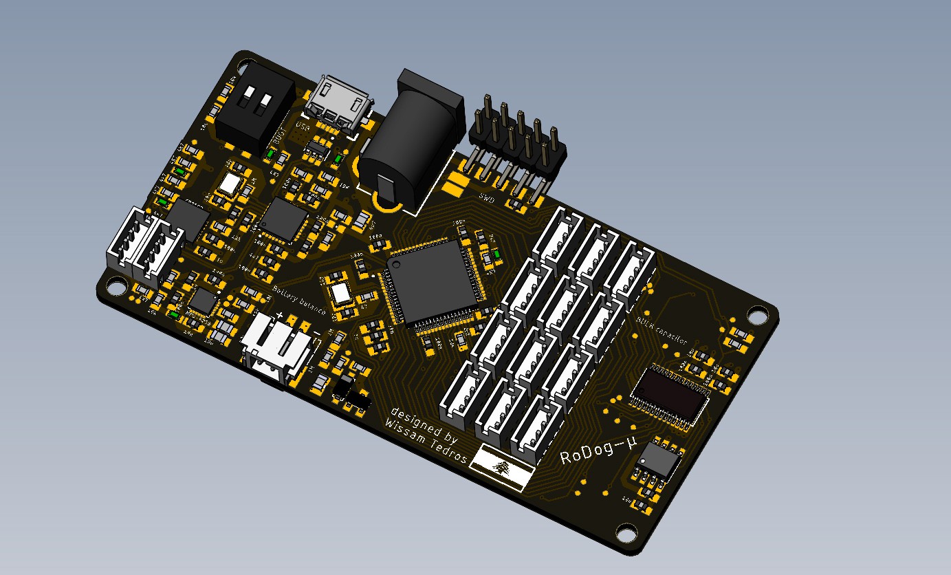
06/14/2021 at 22:56 • 0 commentsI finally Got time to assemble my PCB for the robot, 4 layers, controlled by an STM32f405RGT6,
it features:
- 12 PWM outputs for controlling RC servos
- 12 ADC position feedback, from the Servos' potentiometer
- 12 Shunt resistors of 0.1ohms, for current feedback, this signal is then amplified with a non-inverting op-amp circuit to a good readable range, 0~2.7V, an AD7490 handles the reading and is connected to the MCU by an SPI bus
- 9DOF (accelerometer , gyroscope , magnetometer) inertial measurement unit MPU9250 connected to the MCU by I2c
- small FPC connectors(for future plans), I have a plan to make a small 360 scanner, using a hard disk DC motor, so I also added an H-bridge for that, and some GPIOS.
- BQ5887 for 2S Li-ion/Li-Po batteries charging and balancing, to charge the robot from the USB port
- USB-Hub for STM32 output and cp2102 USB to UART bridge to program the ESP32-camera
- 4mb external flash memory
- additional UART/I2c breakouts and an optional port for a small OLED display
- USB B-micro for charging/ and differential pair connected to the MCU
- SWD interface for the STM32
![]()
![]()
![]()
![]()
![]()
I have turned on the board, computer sees it, and the ST-LINK recognizes it, we're looking Good!
![]()
-
earlier versions (v2)
03/20/2021 at 00:16 • 0 comments![]()
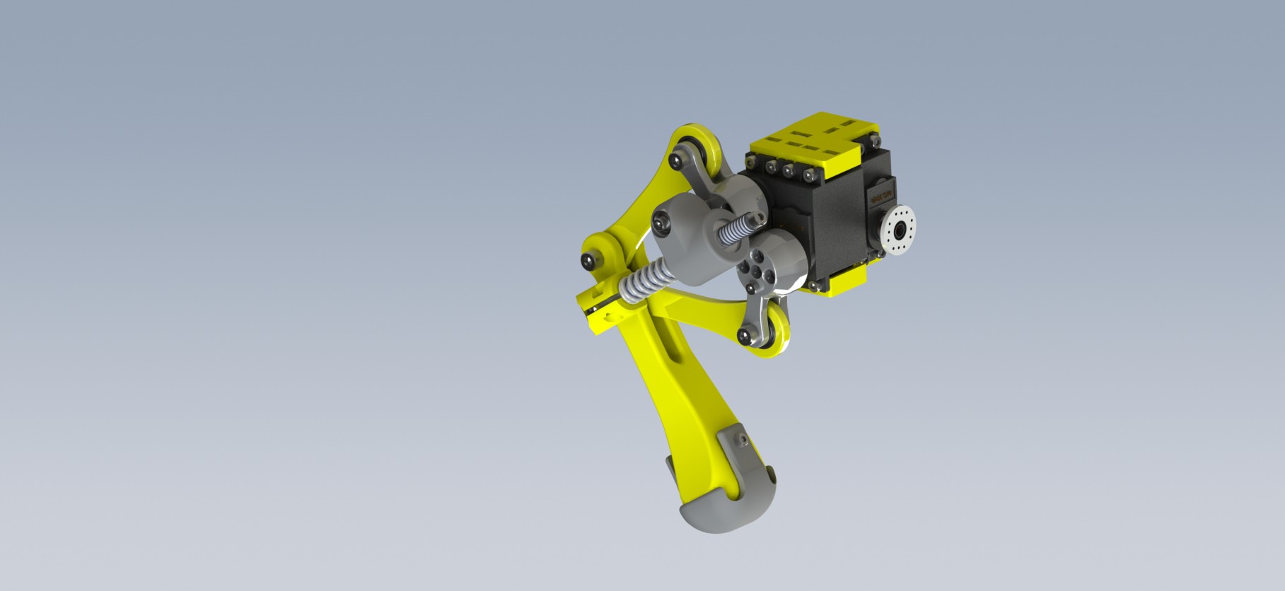
for version 2 , I used a teensy 3.5 and a raspberry Pi 3A+, connected together on a breakout PCB that I milled on a hobby CNC engraver, the teensy was a good deal between performance and accessibility, but I knew that I had to design my own board someday for a better performance. Version 2 was a really good example of CAD != reality, this project being my first major one, I just thought that by perfectly defining all my constraints in CAD and fully defining an assembly, I would achieve a perfect fit, a smooth as silk mechanism, and rigid bodies that absolutely won't twist, bend, or even crack under load, especially 3D printed parts, lets just say that I did not completely know what I was doing, just having fun in CAD. The design was not terrible, it just didn't match my expectations, it is important to note that I don't really have a lot of experience in CAD, I taught myself how to use SolidWorks.
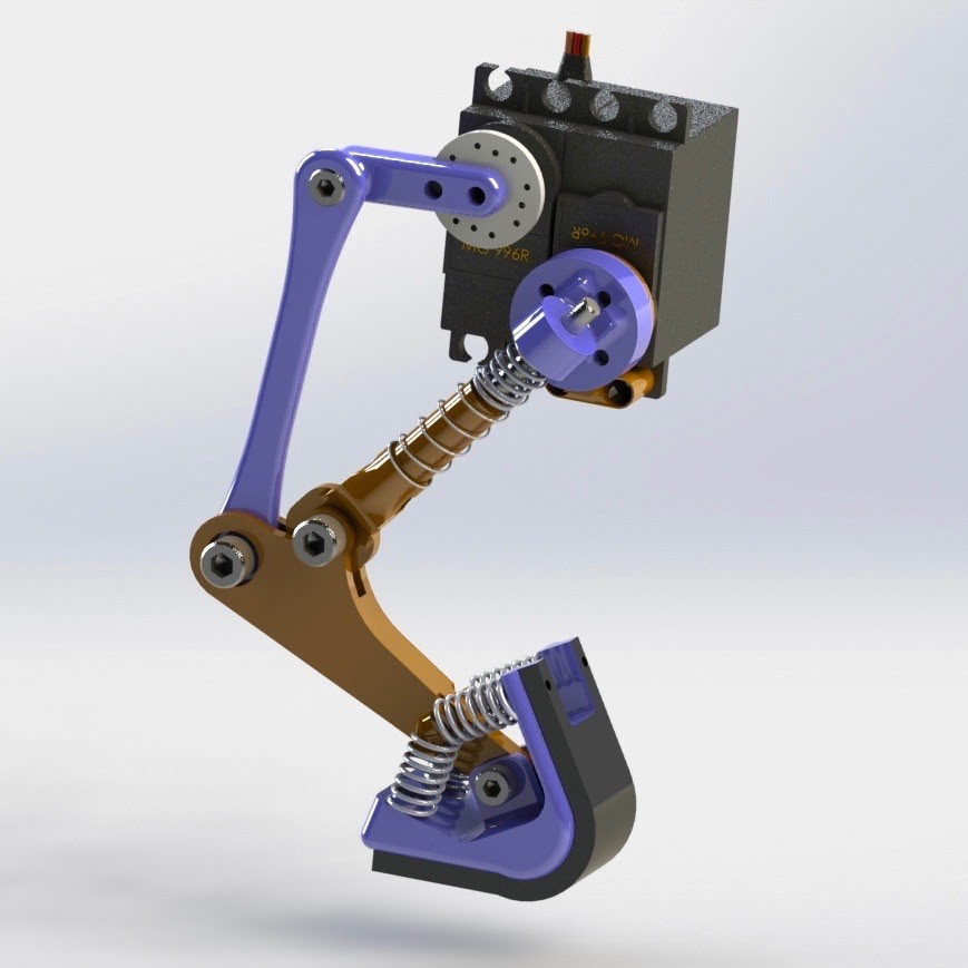
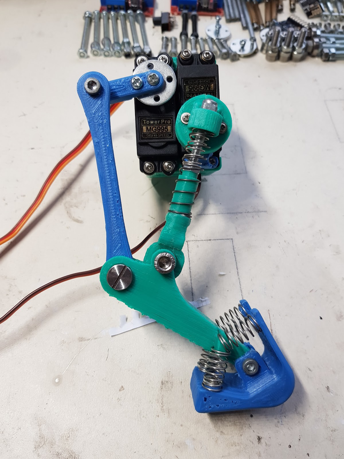
my Leg mechanism was a constrained 4 DOF manipulator, a very stiff spring sets a constraint length between the end effector leg link and one of the cranks attached to the motor, the idea was to let the spring absorb any sort of load on the robot. As stated in a previous log, I actually swapped replaced this weird mechanism, and replaced it with a normal leg mechanism, where the joint are just connected serially, each motor on a joint instead of parallel control, I achieved with that design my first static movements, (pitch roll yaw, and XYZ body translations) with an inverse kinematic model.
![]()
![]()
-
earlier versions
03/19/2021 at 23:13 • 0 comments![]()
![]()
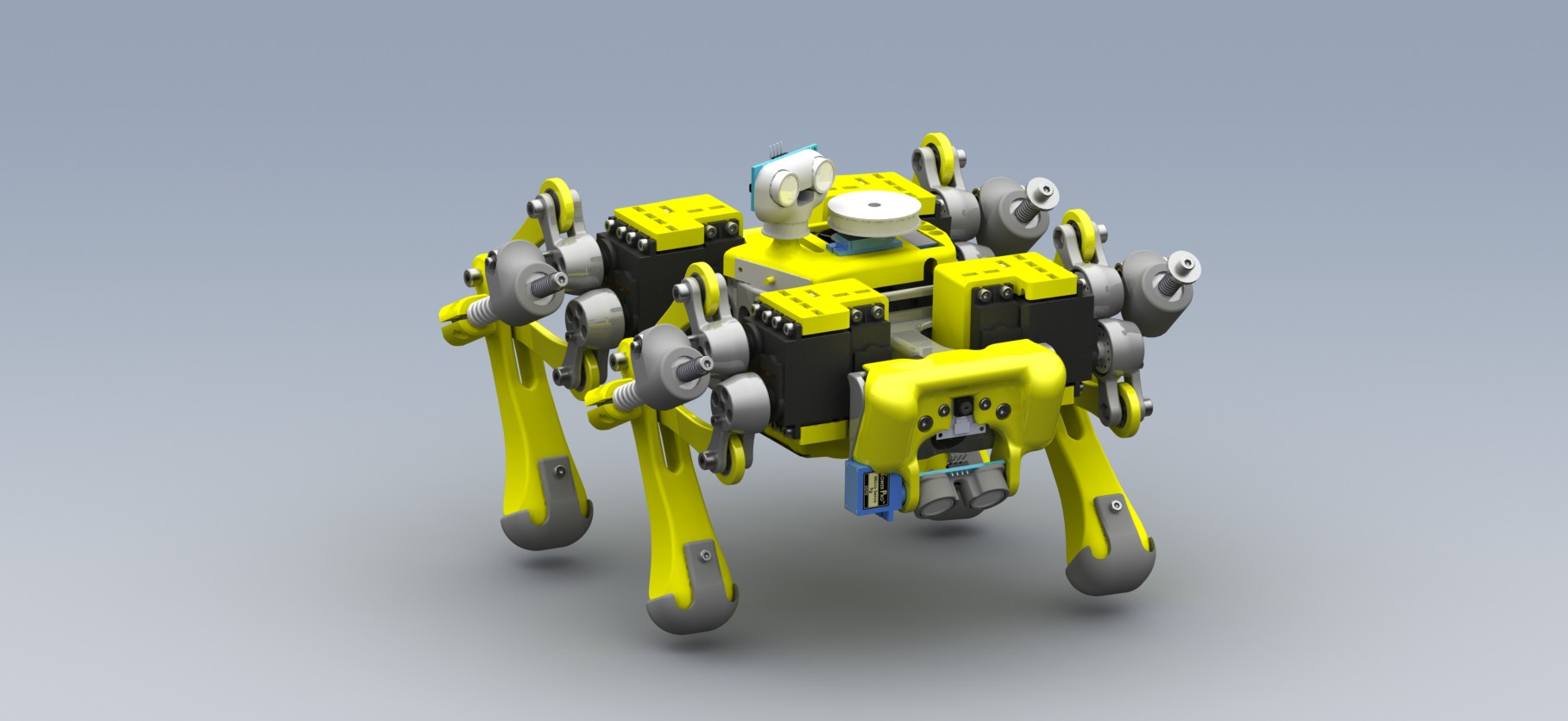
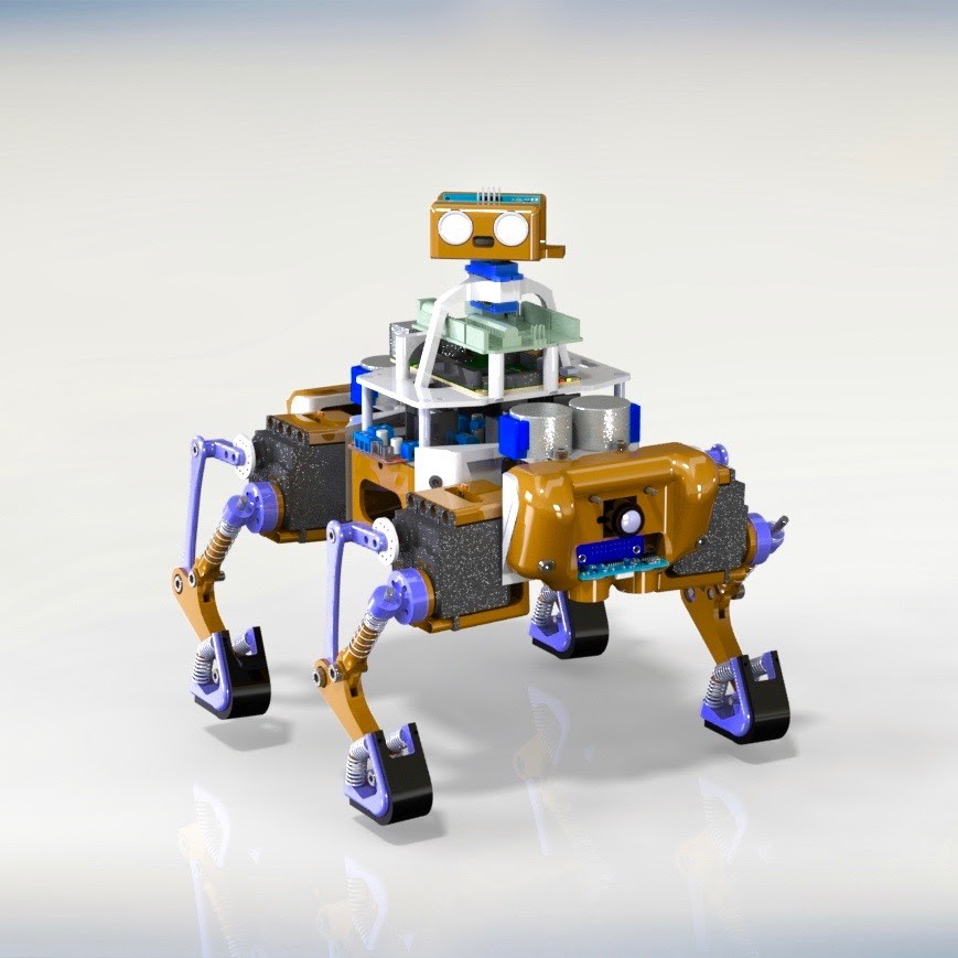
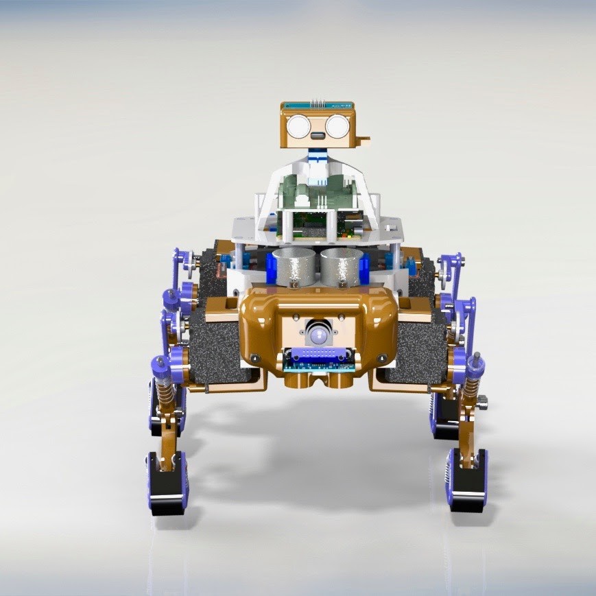
these first few project logs are going to describe the various iterations of this robot, before I decided to publish it on Hackaday, I first tried the approach of the 5 bars mechanism for the legs for versions one and 2, version one was not even assembled as I felt it was never going to work, after assembling version 2, I had some successful static motions, but the robot was consuming a lot of power, because the mechanism was just over-constrained, so I kept the same chassis and electronics and just went with a normal leg mechanism, where all the joints are actuated in a serial manner, I Got worlds of difference in performance, and the power consumption was exactly what you'd expect from 12 20kg.cm digital Servos, I just used an Arduino Uno and a raspberry Pi in my first prototype I knew it was just a test, so I ended up only printing the leg mechanism, to test it, and realized that it wasn't capable of actuating a robot. So I immediately started designing version 2
![]()
![]()