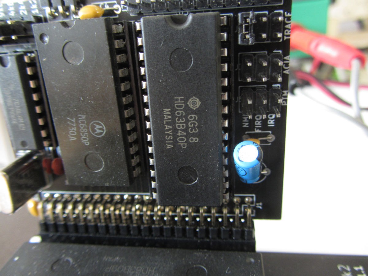
Finally I fixed the Trace function in ASSIST09. It appeared the only MC6840 I had was faulty. Replaced this with a HD63B40 and trace works as expected. Here a selective screendump (comment after the ;):
>D 0000 001F    ; Dump memory locations of the HelloWorld program

      0  1  2  3  4  5  6  7  8  9  A  B  C  D  E  F
0000 30 8D 00 06 3F 03 3F 06 3F 08 48 65 6C 6C 6F 20  0...?.?.?.Hello
0010 57 6F 72 6C 64 04 FF 00 FF D7 FF E2 BF 00 FF 00  World...........
>

>G 0000        ; Run the program.

Hello World

>R        ; Change the Program Counter to the start of the program
PC-000A A-2E B-94 X-000A Y-18B2 U-A400 S-181C CC-F4 DP-18
PC-0000

        ; Typing '.' at the cursor generates this output
>.OP-308D PC-0004 A-2E B-94 X-000A Y-18B2 U-A400 S-181C CC-F0 DP-18
>.OP-3F03 PC-FFE8 A-2E B-94 X-000A Y-18B2 U-A400 S-1810 CC-F0 DP-18
>.OP-6E9D PC-F895 A-2E B-94 X-000A Y-18B2 U-A400 S-1810 CC-F0 DP-18
>.
Hello WorldOP-0C90 PC-FA3B A-01 B-F0 X-0016 Y-18B2 U-A400 S-1810 CC-F4 DP-18
>.OP-3B04 PC-0006 A-2E B-94 X-000A Y-18B2 U-A400 S-181C CC-F0 DP-18
>.OP-3F06 PC-FFE8 A-2E B-94 X-000A Y-18B2 U-A400 S-1810 CC-F0 DP-18
>.OP-6E9D PC-F895 A-2E B-94 X-000A Y-18B2 U-A400 S-1810 CC-F0 DP-18
>.
OP-0C90 PC-FA3B A-01 B-F0 X-FA3D Y-18B2 U-A400 S-1810 CC-F4 DP-18
>.OP-3B04 PC-0008 A-2E B-94 X-000A Y-18B2 U-A400 S-181C CC-F0 DP-18
>
        ; Cool thing is that the trace works with both RAM and ROM based code.
Below the listing of the HelloWorld program
                      ; Source: https://www.youtube.com/watch?v=C_q_RNpLNHo&t=1522s

                      ;*************************************************************************
                      ;       HelloWorld.asm
                      ;
                      ;       A simple 'Hello World' characher output test.
                      ;       for ASSIST09 based system.
                      ;       Call with ASSIST09 'G' Go Subroutine command to Entry address.
                      ;
                      ;       Author: Greg
                      ;       Date:   15/02/2002
                      ;       Modified for SWI $08, fjkraan, 20250827
                      ;*************************************************************************
 0000                 Entry   EQU     $0000
 0003                 PDATA   EQU     $03
 0006                 PCRLF   EQU     $06
 0004                 EOT     EQU     $04
 0008                 MONITR  EQU     $08
                      ;
                              ORG     Entry
                      ;       LDX #Message is how we would normally load the index register pointer.
                      ;       ie. Simply loading X with an absolute address.
                      ;       But LEAX is the MC6809 Load Effective Address approach which generates
                      ;       preferable and more flexible "position independent code".
                      ;       ie. Load X with the Program Counter Relative address of the Message.
 0000 308D0006                LEAX    Message,PCR
                      ;       Call the PDATE service routine.
 0004 3F                      SWI
 0005 03                      FCB     PDATA
                      ;       Call the PCRLF service routine.
 0006 3F                      SWI
 0007 06                      FCB     PCRLF
                      ;       Return to Monitor.
 0008 3F                      SWI
 0009 08                      FCB     MONITR

 000A 48656C6C6F2057  Message FCC     "Hello World"
 0011 6F726C64
 0015 04                      FCB     EOT

                              END

SYMBOL TABLE
     ENTRY 00 0000       EOT 00 0004   MESSAGE 02 000A    MONITR 00 0008
     PCRLF 00 0006     PDATA 00 0003
6 SYMBOLS

0 error(s), 0 warning(s)
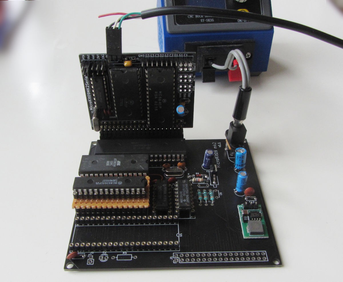
Finally I managed to find time to configure the Motorola monitor Assist09 to the MicroKit09. It is a very small monitor that uses an ACIA (6850) and optionally a PTM (6840) to work.
Short introduction into Assist09.
All commands and hex values should be uppercase. Commands and arguments
are separated by one or more spaces.
A complete description and assembly listing of Assist09 is in the
Motorola MC6809-MC6809E 8-Bit Microprocessor Programming Manual, Appendix B
Command Name Description Command Entry
Breakpoint Set,clear,display, ordelete breakpoints B
CallCall program as subroutine C
Display Display memoryblockinhexandASCII D
EncodeReturn indexed postbyte value E
GoStartorresume program execution G
LoadLoadmemoryfrom tape L
Memory Examine oraltermemory M
Memorychangeor examine lastreferenced /
Memorychangeor examine hex/
NullSetnewcharacterandnew line padding N
OffsetCompute branch offsets O
Punch Punch memoryon tape P
Registers Display oralter registers R
Stlevel Alter stack tracelevelvalue S
TraceTracenumberof instructions T
Trace one instruction -
VerifyVerify tape tomemoryload V
Window Set a window value W
Screendump of a Assist09 session
The monitor code range is F800-FFFF, RAM is expected at 1800, ACIA at A400 and the PTM at A800.
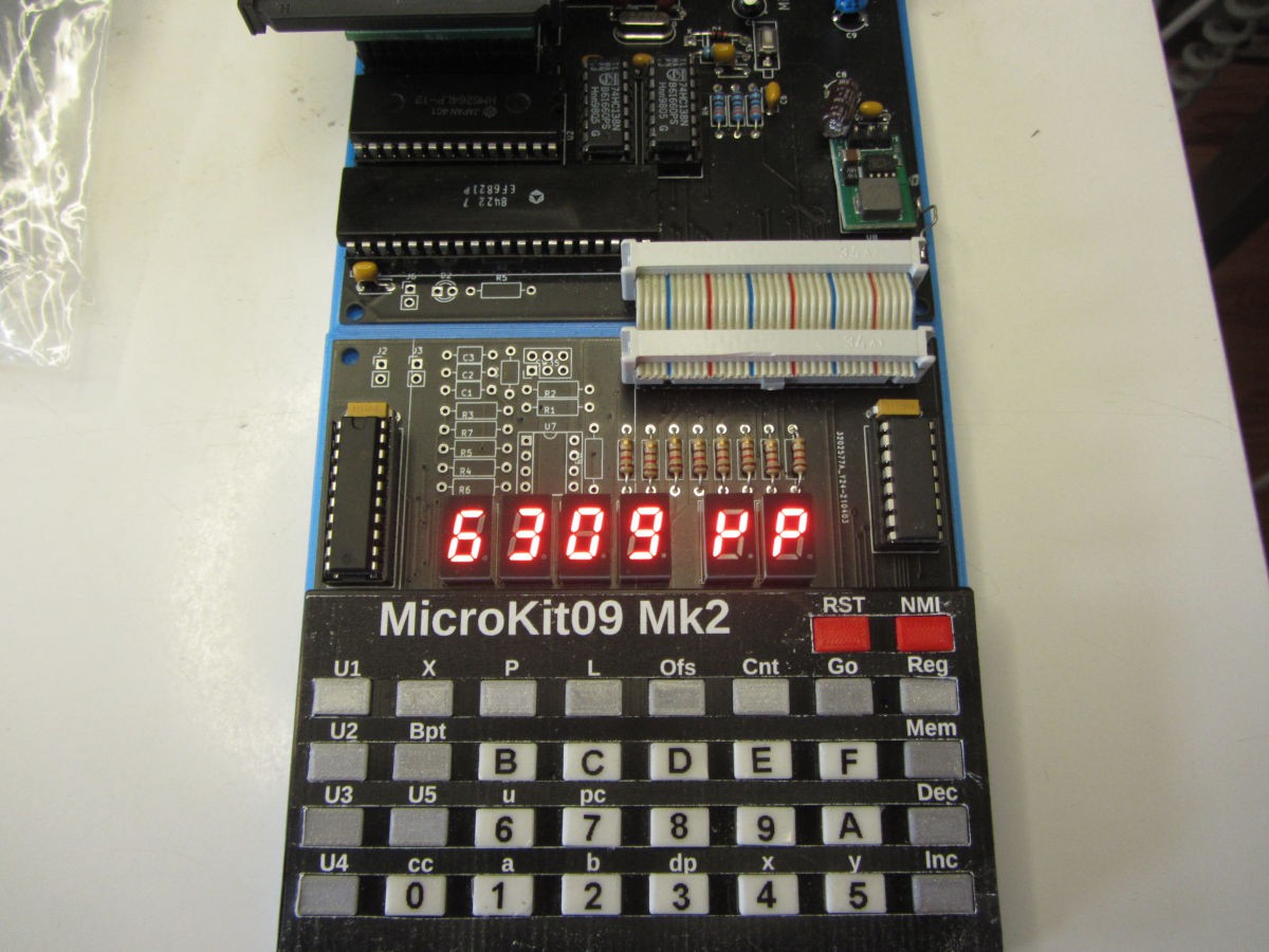
Minor update of the monitor, including a processor check at startup. Instead of the underwhelming '-' prompt, now it checks and displays the actual processor type. Any key will resume the startup process.
The MicroKit09 mk2 v1.1 CPU board has a serious shortage with address lines, so isn't really production ready. It is fixable however, with some wires (note this is a corrected version). - All repairs can be done on the solder side - Cut both traces to U2-2 - Add wire between U4-1 and U7-19 (this fixes A10) - Add wire between J3-3 and U2-2 (this fixes A12) - Add wire between J4-3 and J3-2 (this fixes A11) This solution has the disadvantage that the jumper J3 cannot be used anymore to select a 2k byte RAM.
The MicroKit09 mk2 v1.1 I/O board is ok and is tested with the low profile switches and keys. An image is added to the project gallery.
The monitor (1.8 and 1.9) has the annoying habit of not showing locations which have no memory. This can be fixed by nopping out two instructions in the EXMEMO call, just past the PREXIN label:
    CMPA ,S+     ; MEMOIRE ABSENTE OU MEMOIRE MORTE?
    LBNE RPOINT     ; OUI, ALLUMER PROMPT ET SCRUTER
Needs more testing however. (The latest version at the Github repo has a more elaborate fix, which uses the decimal points as indication there is no memory at this location.)
It it not sure I will create, test and publish newer versions of the boards.
Additionally, the EPROM can be replaced with an 8kx8 2764 or equivalent by inserting a 28-pin socket on top of the 24-socket. Note the U7 numbering is based on 28 pins. Here the extra wiring is:
- Add wire between J3-3 and U7-2
- Add wire between U7-26 and U7-27
- Add wire between U7-26 and U7-28
By using our website and services, you expressly agree to the placement of our performance, functionality, and advertising cookies.
Learn More
 fjkraan