What’s awesome about this tool is that it automatically assigns textures and even adds tin to the pads, making the PCB look like it’s actually soldered. I tried Blender a couple of years ago, and it has this weird way of handling textures by connecting blocks, kind of like programming - it’s interesting, but I didn’t like it (I’m not really into graphic design). With this tool, though, you don’t have to deal with any of that.
There are still a few things you’ll need to do manually in Blender, like adding light sources, setting up a background, and configuring the camera. However, I managed to figure it out in one evening, so it’s pretty easy.
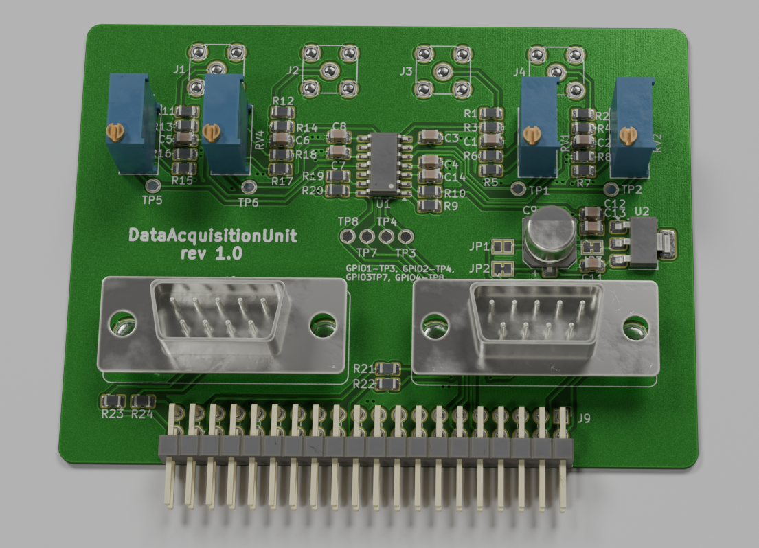
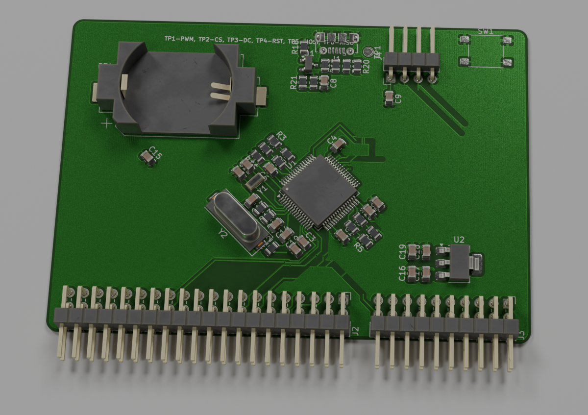
Below, you can see some of the renders I made. They’re not perfect since I’m new to Blender, plus I limited the rendering samples to speed up image generation, so the output’s a bit noisy.
Last week, I was working on cleaning up the CMake files and setting up Docker. It was quite difficult because I don't know either of them well, but in the end, it works pretty well.
Personally, I really like the idea of Docker because, in a file, you can configure your environment and - here’s where the magic is - this file is treated as configuration/code. Meaning, it’s parsed and checked by a machine. It’s not a README that’s never up to date, but something that gets “compiled,” and you get errors if something is wrong. Some DevOps guys would probably laugh at this description, but it’s true :)
I’ve also experimented a bit with hpp2plantuml, a tool to generate UML class diagrams based on existing code. I wasn’t happy with the results as it omitted a lot of connections that exist in the code, but the setup is easy, and what it generates is accurate (it’s just not complete). I even have a build for that!
Another tool I checked out is include-what-you-use. Setting it up isn’t trivial, at least on Linux, as it needs to be downloaded and compiled manually - the old-school way. It also requires, AFAIK, Clang as a compiler, meaning you need to have a build version using Clang. I haven’t yet paid much attention to what it generated, so I can’t say if it’s useful for embedded projects. BTW, it was developed at Google.
I also removed the build for Valgrind because I intentionally don't use either the standard library or dynamic allocation, so it was kind of silly to include that tool.
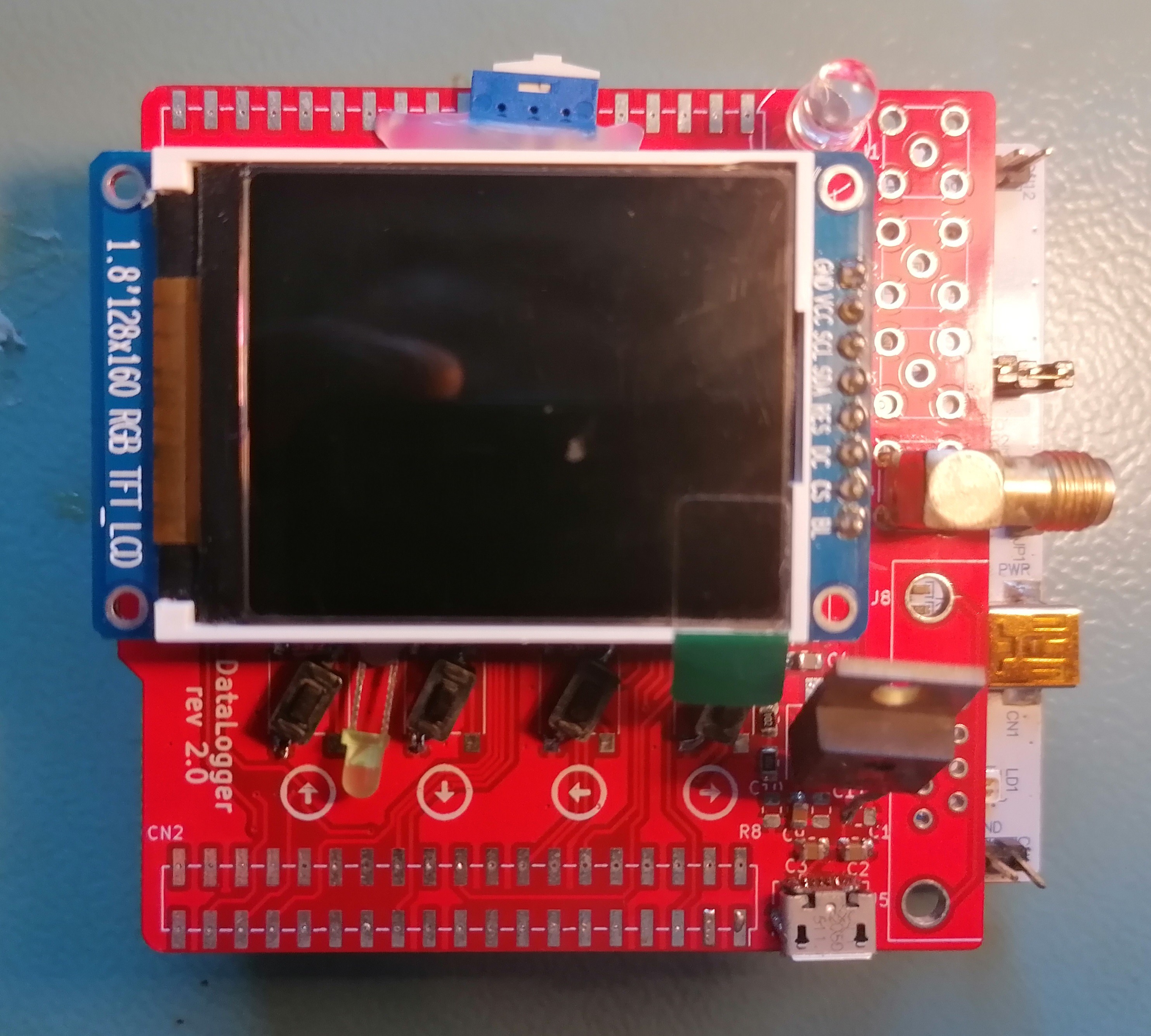
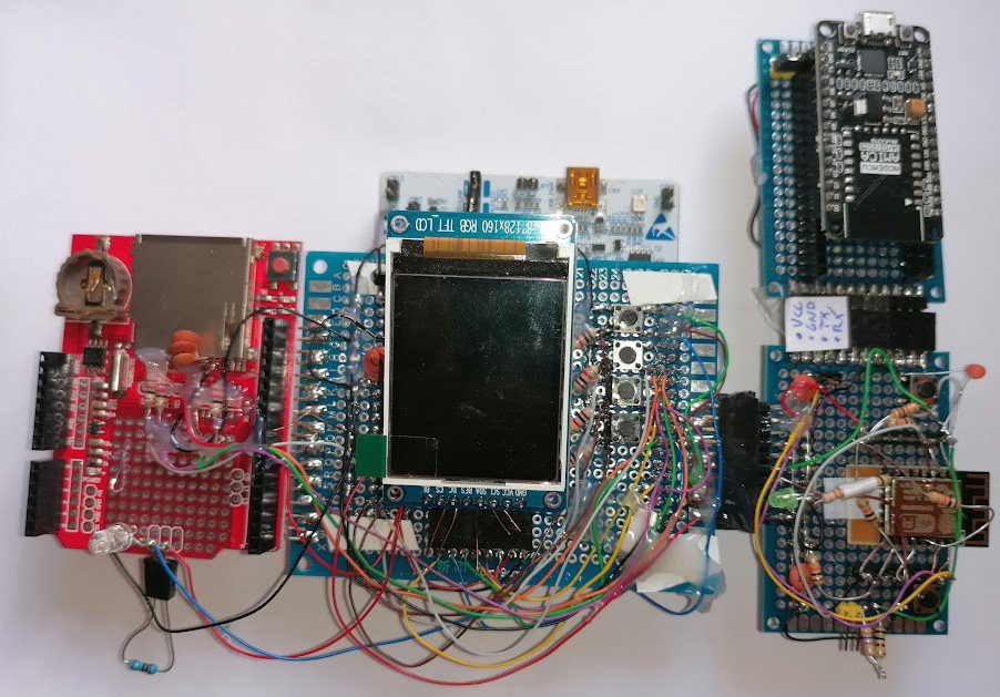
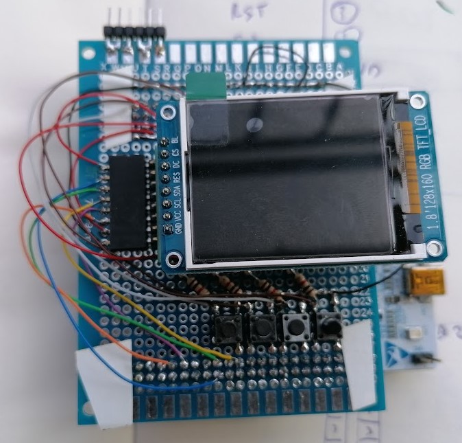
I have made a new version and it was working (well, not all of it was/is working but major parts yes). This is also the first time the project has its PCB so it looks much better than previous version.
What you see is NUCLEO board (white PCB at the bottom), my PCB (red one) and the LCD with its own blue PCB (LCD comes with this blue PCB but I think that maybe I will desolder it and solder it directly into my board, I don't know).
The NUCLEO and the logger PCB are connected via SMD pin headers that.. I forgot to buy. I've used standard troug-hole pin headers, but I didn't solder them quite well (it's a different footprint) and that make a lot of problems with missing connections. I've sped three hours at least on that.
ESP8266 and STM32 talsk to each other via UART, that's make me happy, that was my main goal for this version. I can dim the LCD, although the algorithm is rather primitive. Buttons works too. I will add debouncing in the software later.
The LCD doesn't work now, probably because some pins did unconnected again, but it was working so I know that HW design is good. Same with SD card.
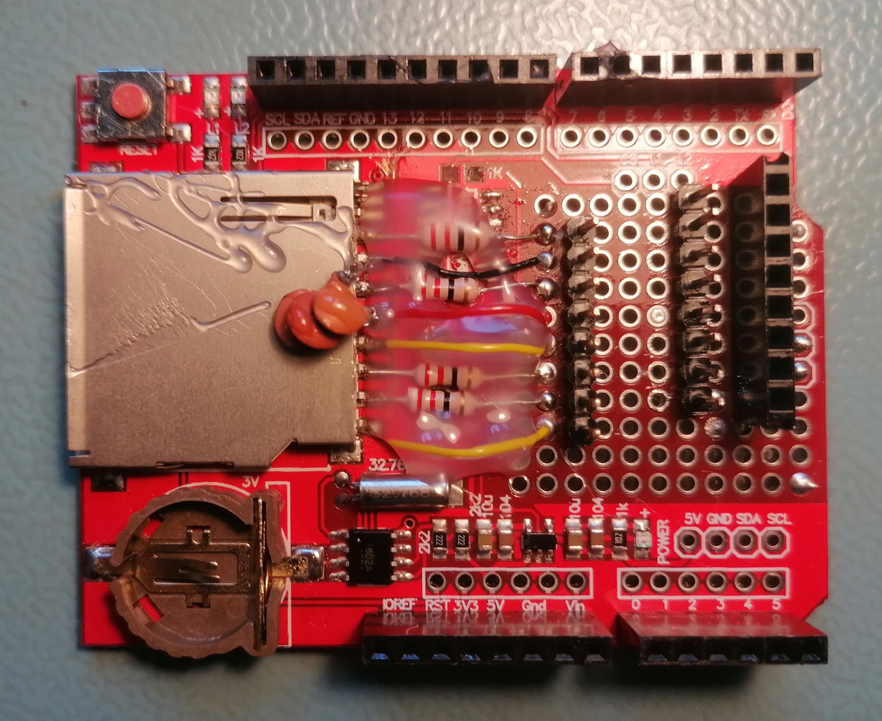
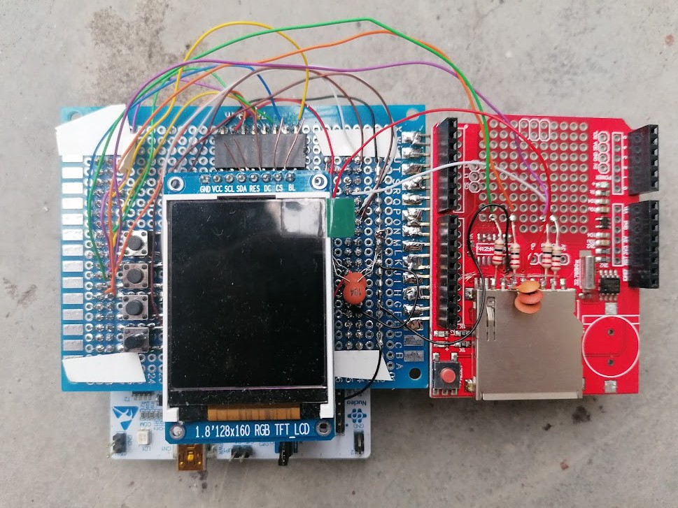
I won't have access to my tools, so I made a small PCB with an SD card and a connector for the LCD display to overcome the current problems with the PCB. It's based on the existing Arduino shield, fun fact it's red too.
I tried to use a lot of modern features in the code (which doesn’t compile, by the way). I have unit tests (Google Test, Google Mock), static analysis (Cppcheck), and dynamic analysis (Valgrind, though it doesn’t really make sense for this project, but the diagrams look cool). I’ve got test coverage, and I’ve also added docs and docs coverage. The downside is that CMake (yes, I’m using CMake now too!) looks like garbage. I’ll have to take a look at that.
I’ve switched to Visual Studio Code. It’s 2024, no more Eclipse-based garbage.
What do I plan?
I want to get rid of the NUCLEO board and use the STM32 chip directly on my board. This will solve the connector issues and make the device smaller and cheaper.
My second goal is to use Grafana for result visualization. It’s an awesome open-source tool for displaying measurements, with a web API, and it can run on a Raspberry Pi.
This is the latest hardware version (rev 2.0). The ESP module has been added, and it has been successfully flashed. Several hardware changes have also been made to the PCB design.
SD card works OK, here are interesting things that I've learned:
There are two protocols to communicate with SD card - SPI (slower, but easier) and SD bus, some cards will not work with SPI
The SD card can draw up to 100mA when writing data!
As usual, it's good to add small resistors in series to all pins that are accessible from external, user can insert or remove card, so all data ports can be considered to be accessible from external. This is to prevent ESD damages. For SD card those resistors are in range 40-50R.
It's good to add pull-up resistors to all data lines, otherwise some cards will not work. There are chips on the market with pull-ups and in-series resistors.
The prototype is now a bit bigger than before, because I've decided to cannibalize data logger board for Arduino - back when a shipment from China was for free (in Europe) I'v bought a couple of them - just in case. I don't really need therm since I don't do a lot of Arduino, and this saves me on buying SD card slot and RTC clock. I will add an RTC clock to the design.
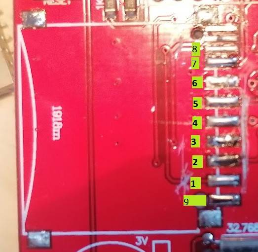
The SD slot was a bit problematic, finally I've de-soldered it to see bottom side and how the card is really connected. It's weird for me because they didn't ignore pin #9, it's accessible even when AFAIK it's unused. So the pinout is like this 9, 1, 2, ..., 8, extra pins for check write protection.
In the next step I plan to setup ESP32, it will involve probably soldering new breadboard to the prototype :)
I've got a small success in reduction of amount of components on the PCB, I tested it on the breadboard -presented before- and i works fine.
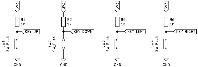
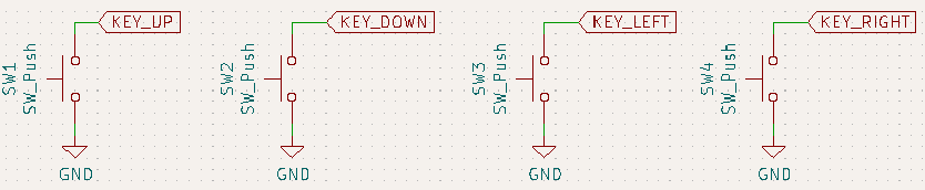
First, I tried to remove the pull-up resistors for switch buttons, below is the original diagram. BTW note that on this schematic there is no low pass RC filter, the filter is used for key de-bouncing, it's used in many open hardware projects, but this can be done in software too.
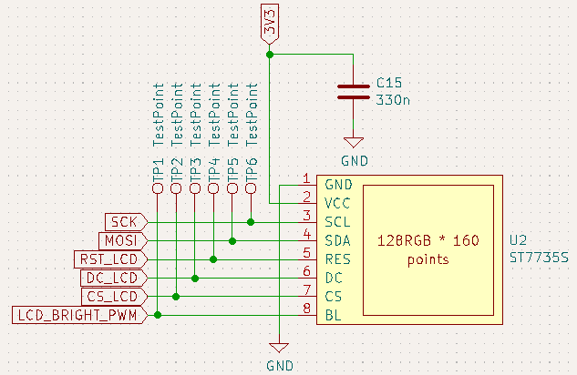
Below is actualized version.
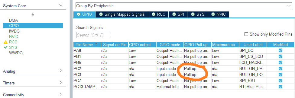
This is possible because STM32 has possibility to configure GPIO as having internal pull-up resistor (it can be an internal pull-down too), so this resistor is still on the schematic, but now I'm using the one build-in into the microcontroller.
Below you can see it on CubeMx.
Note: I still didn't decide to which GPIO connects the key-left and key-right, so those are not configured.
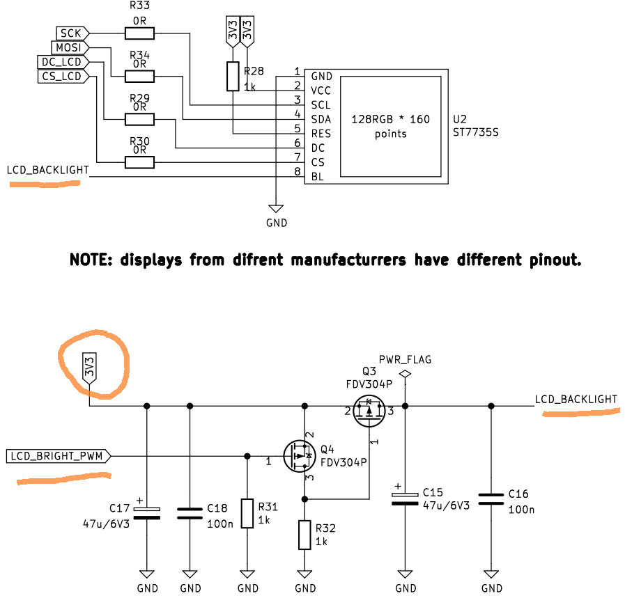
Another IMHO cool optimization is in setting the brightness of the LCD, originally I've planed to use discrete solution that would be driven by PWM. The ST7735S LCD module has a separate pin for LCD brightness, I was thinking that the actual current for backlighting is needed to be provided to this pin. This is not true, it's just a logic signal, that goes to the SOT-23 chip on ST7735S.
The previous version is presented below.
All the bottom part might be removed, because very little current is in real taken from GPIO port and there is no need for buffering transistors Q3, Q4. The buffering is done by small chip on the LCD module. Below is the current version.
I've also been able to communicate with the LCD. Fun fact is that initially I used this lib for ST7735S, but I didn't notice that it's for 80x160 displays. Mine is 128x60. Fortunately, I've found this lib for ST7735 - this one handles my LCD well. From the other side, invocations of HAL functions are a bit hardcoded with business logic, so in order to bring my PC variant for simulation of the device to live, I will have to do a bit of refactoring.
My next steps will be checking circuit for SD card.
I've created a draft of the device using bread-board to check if I correctly connected LCD to stm32 nucleo and to have something to do driver development before ordering PCB. In addition I've added to the board up/down/left/right keys.
Connections changes to original schematic:
LCD connection:
RST - PC7
DC - PA8
CS - PB2
Keys:
up - PC3
down - PC2
left - PC14 (TODO: move it somewhere else)
down PC15 (TODO: move it somewhere else)
I've also tried to solder the part responsible for dimming the LCD but having only MOSFETs in SOT-23 package, it seems to much to work.
 Robert Gawron