One of the things I’ve had to do a lot of recently is designing and building PCB’s, I had been looking for a way to make my PCB assembly process more efficient, and it wasn’t until I saw unexpected maker’s video on the pick and place turntable that he uses to populate his prototype PCB’s that it all came together, the concept of his design provided the bases for which I used to build the Pick-N-Place Wheel, so I’ll like to give a huge shout out to Sean from unexpected maker for sharing his idea and for inspiring the Pick-N-Place Wheel. Watch his video here.
Project Video.
What is it?
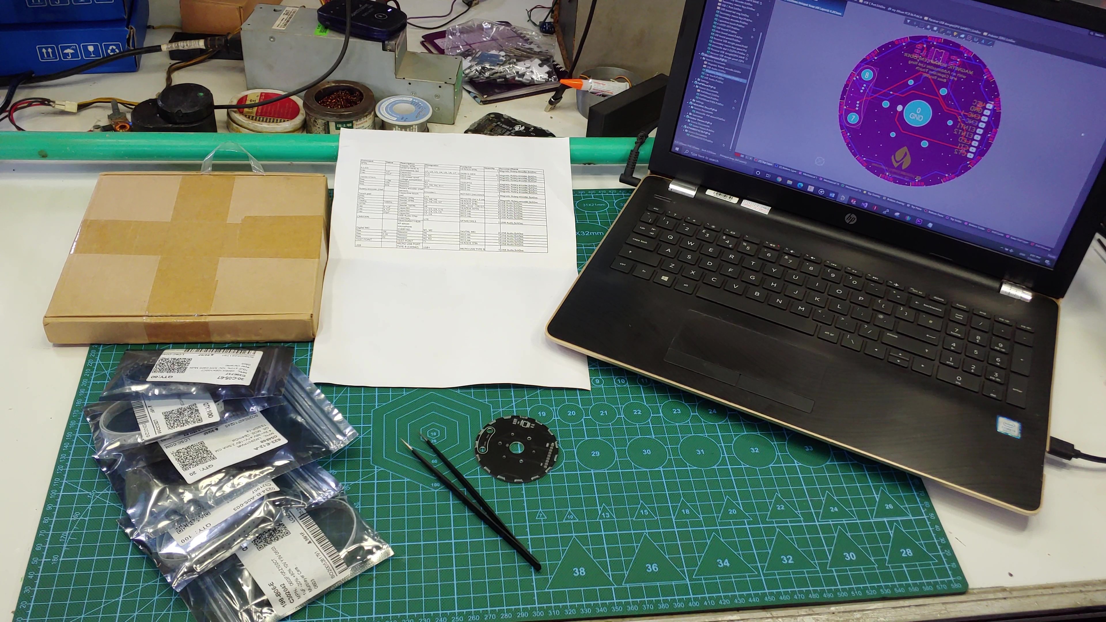
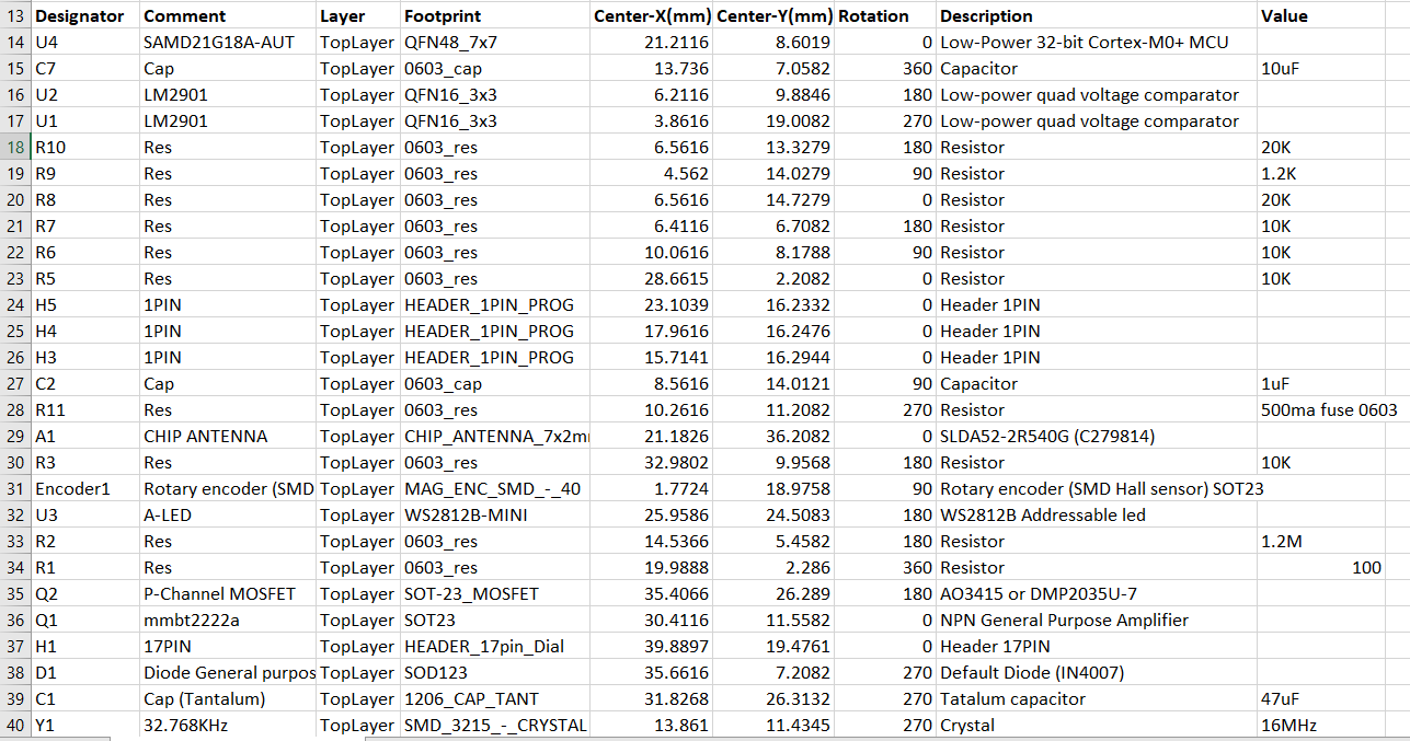
If you have ever hand assembled a PCB, the setup shown in the picture will look familiar to you, to populate a PCB, I would normally have all the components on the table, along with the pre-pasted PCB and a spreadsheet for the board I want to populate, this spreadsheet will usually contain important information like component value, footprint, designator and any other information that’ll enable me to accurately place the components. I would often also have my laptop close by so I can confirm the position on the board where specific components should be placed. With this process I usually avoid any placement errors, but the process can hardly be called efficient, especially if I have to assemble multiple PCB’s…so, my goal for the Pick-N-Place Wheel project is to combine all the elements associated with manual PCB assembly to form a system that is as seamless and as efficient as possible.
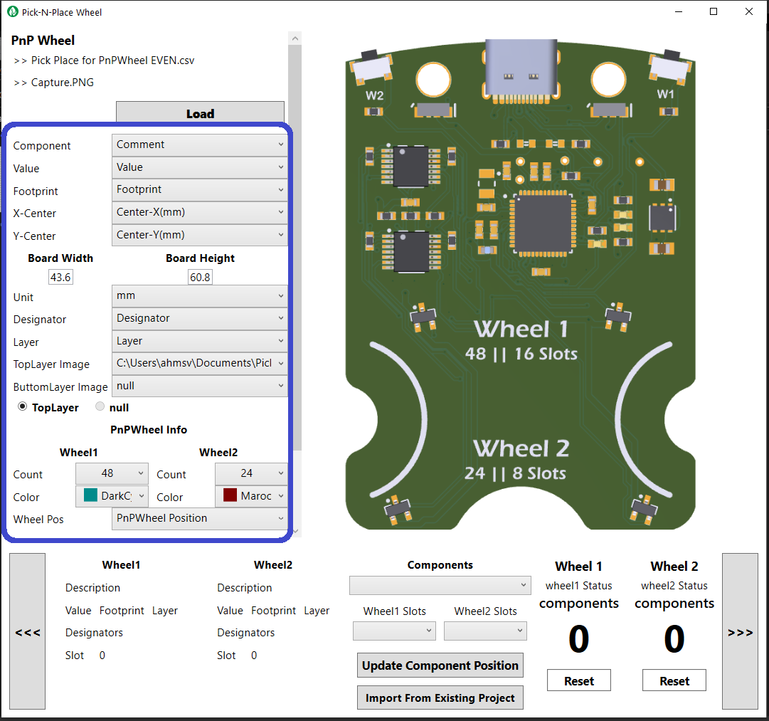
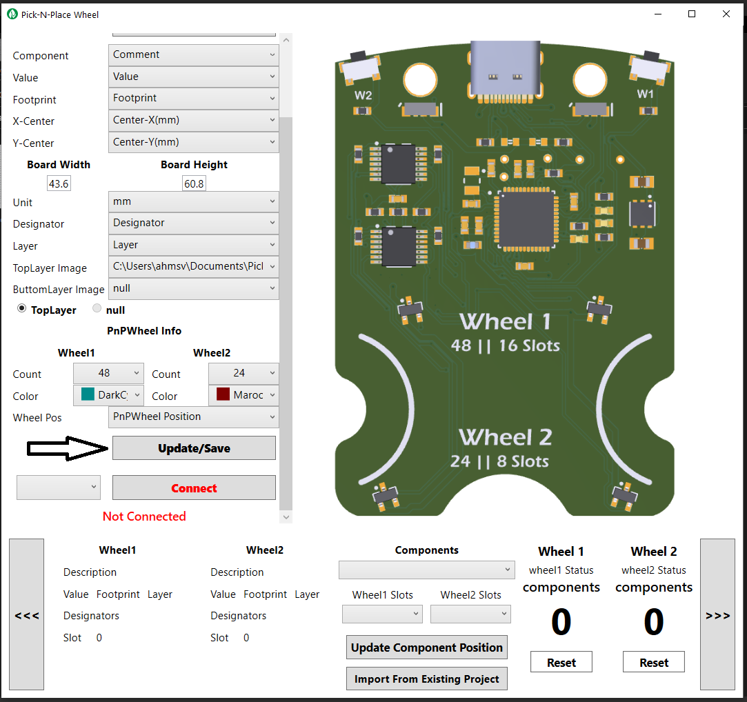
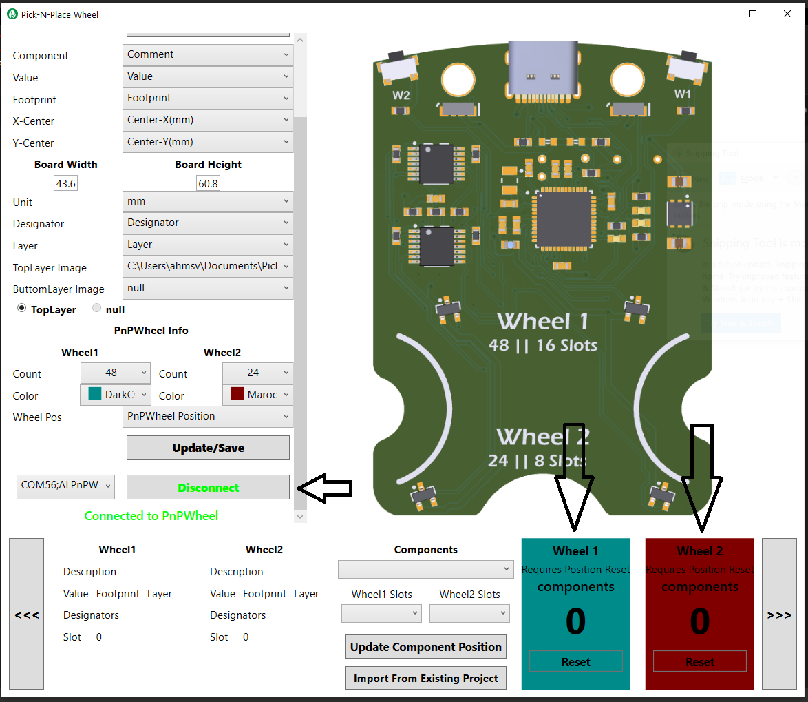
The Pick-N-Place Wheel is not just a 3D printed device, it’s a combination of three main elements: The 3D printed wheel itself which is the hardware, the rotary encoding and slot indexing; the electronics, and the control software in the form of a desktop application. The Pick-N-Place Wheel will not function as its intended without these three elements.
THE WHEEL
The wheel’s function is primarily to hold your components in indexed slots for when your populating a PCB, but it also doubles as the permanent storage for those components, thanks to the built in twist locking mechanism.
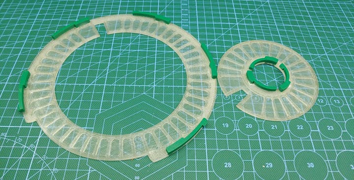
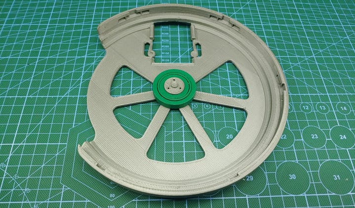
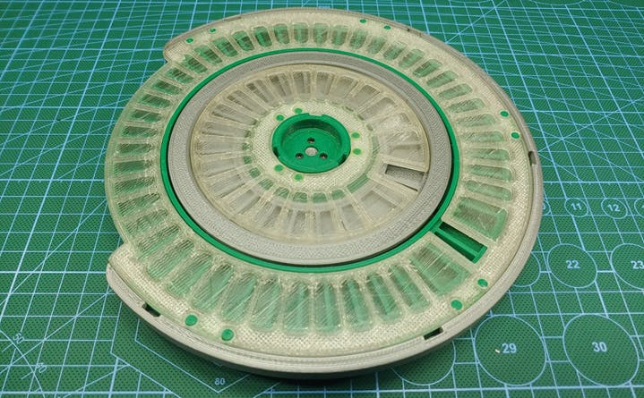
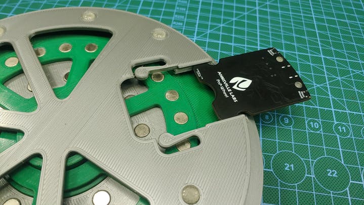
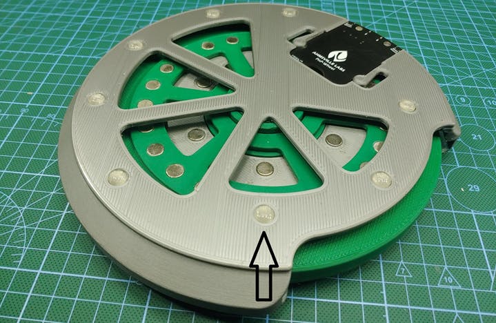
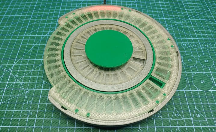
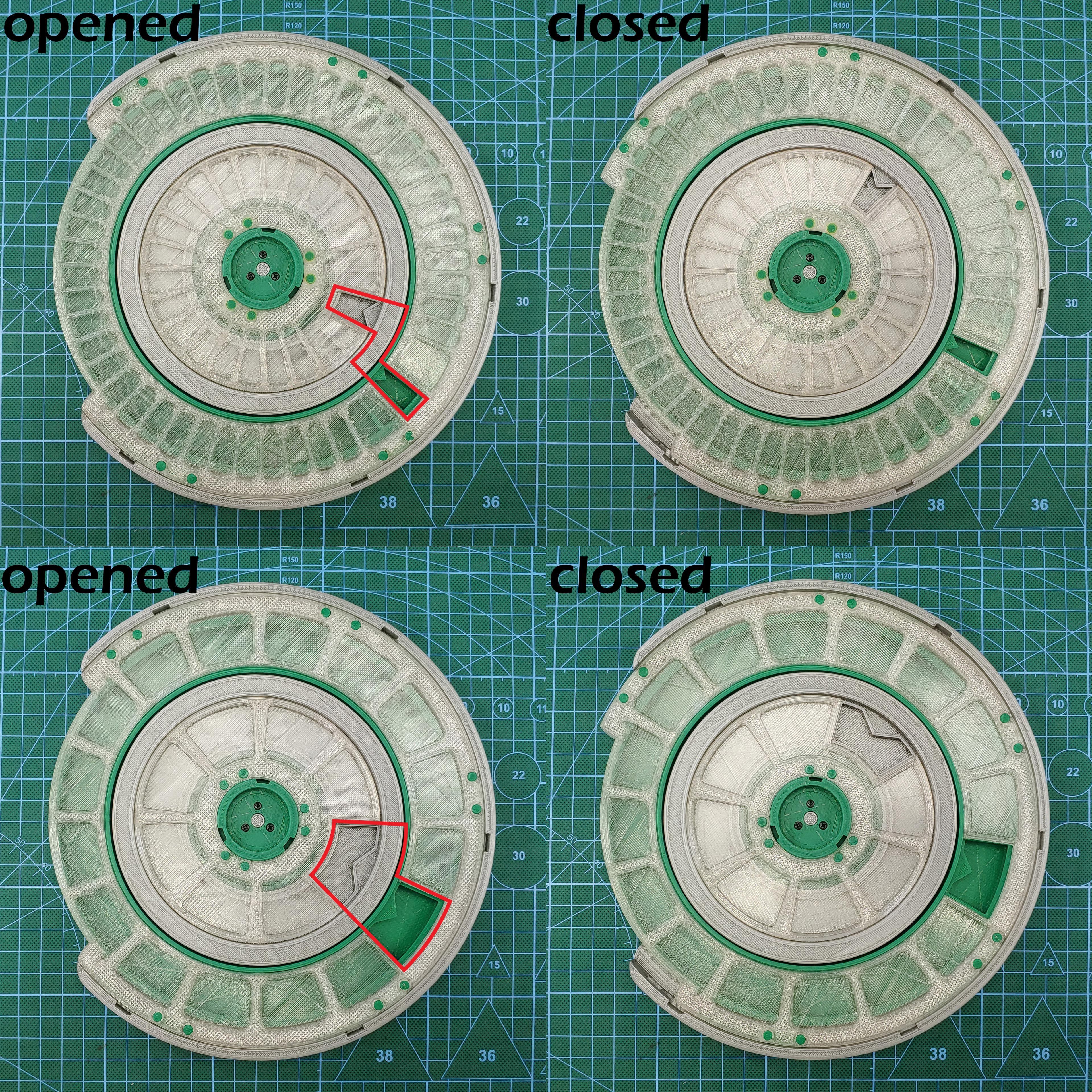
The wheel’s transparent top cover has a few flexible 3d printed tabs glued to it, this tabs fit into matching slots on the wheel, so that when you turn the top cover in one direction it creates a 1mm separation from the wheel (opened state), allowing the wheels to rotate freely during board population, and when the wheel needs to be stored away, the cover can be turned in the other direction which lowers it back down unto the wheel (closed state), sealing the components in their slots and preventing them from falling out or falling into another component’s slot. So instead of keeping components in the anti-static bags that they came in, the Pick-N-Place Wheel can be used to index and store them.
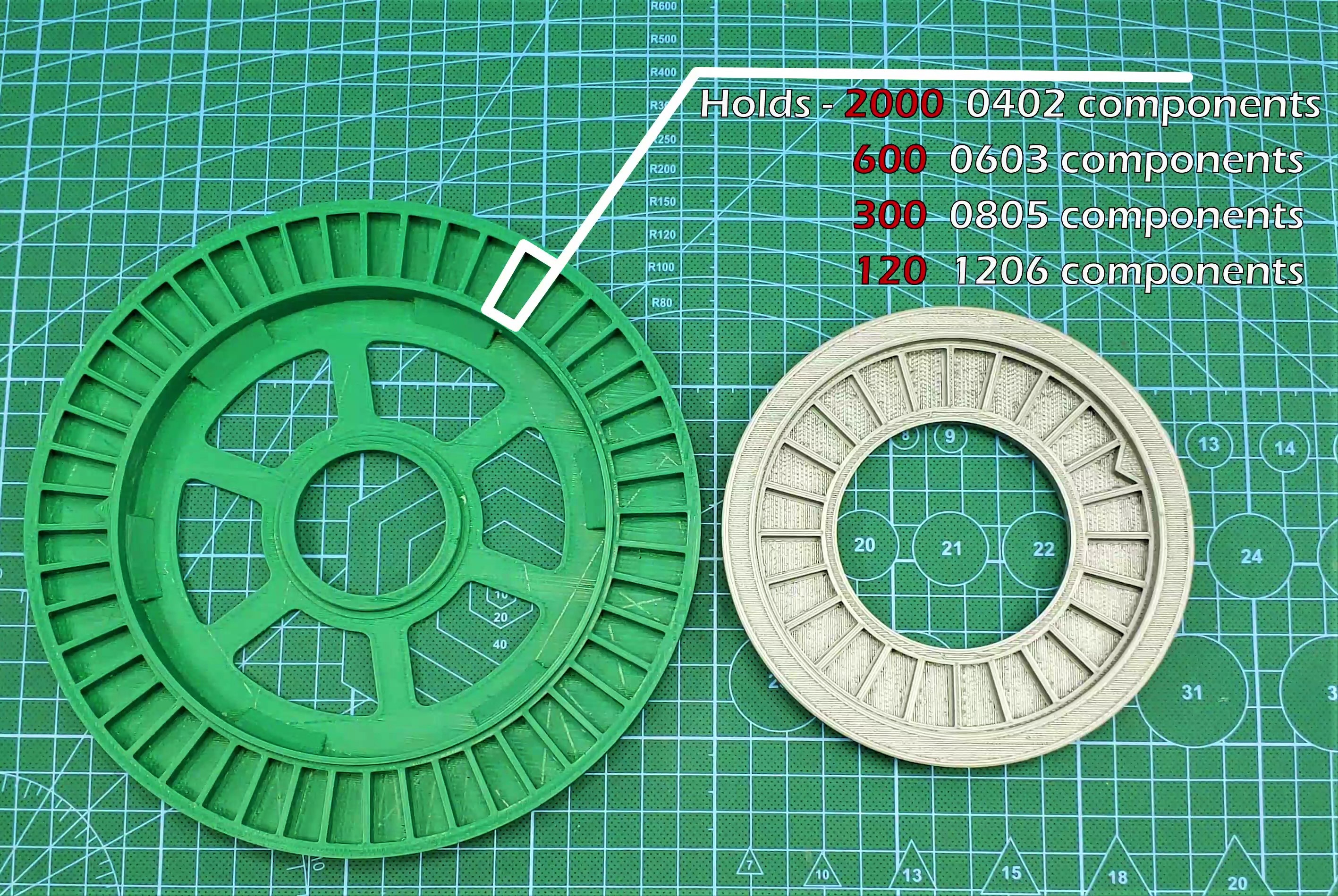
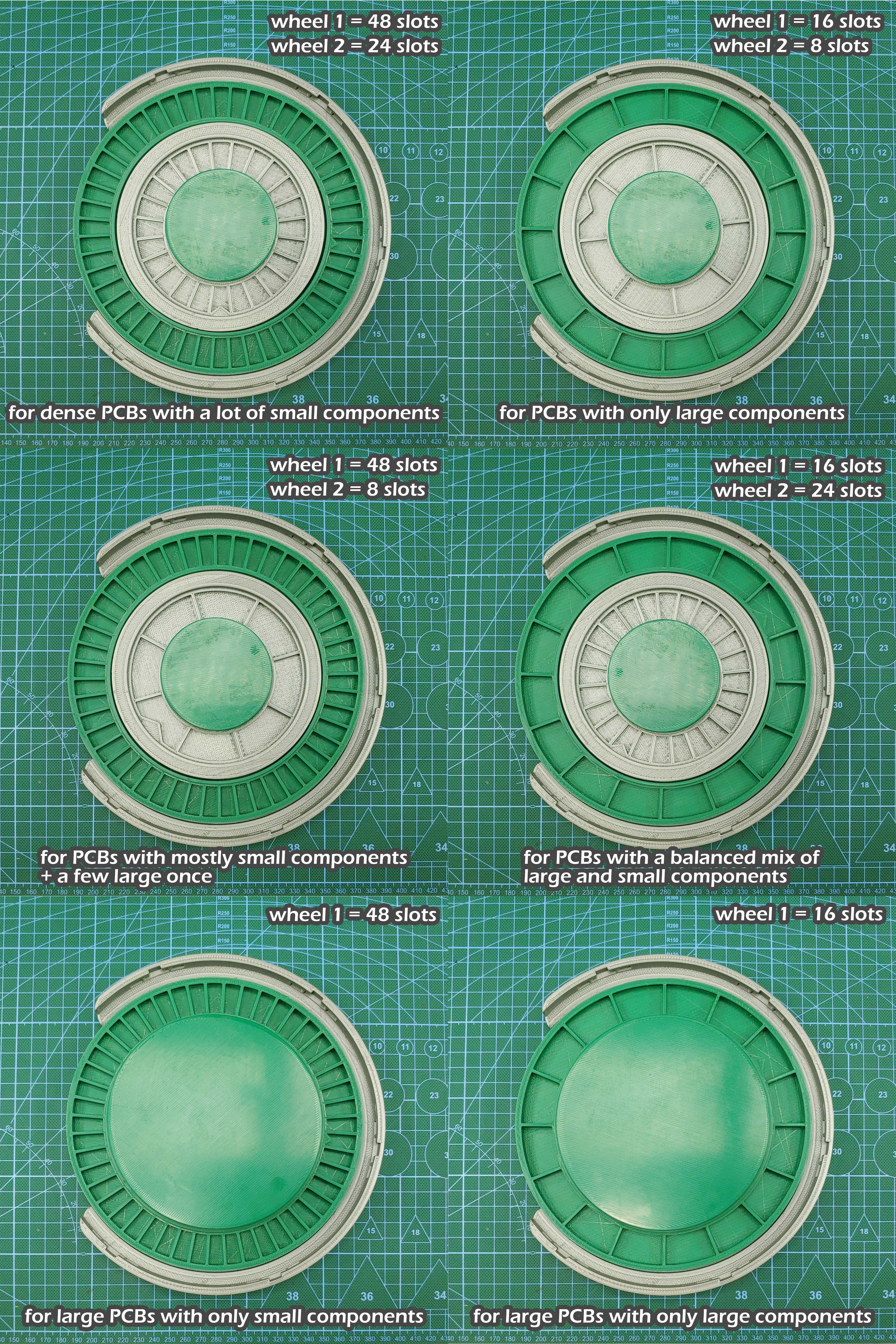
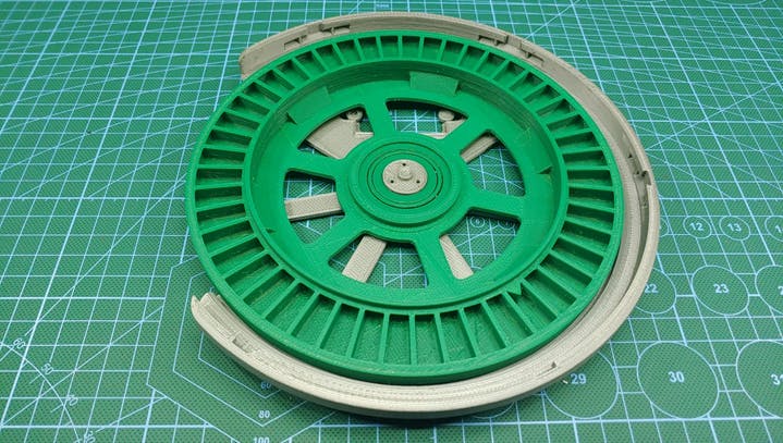
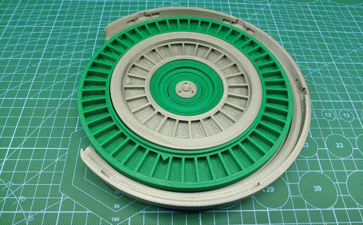
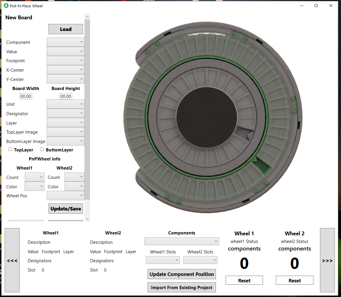
The Wheel is designed to hold two separately encoded wheels, one large outer wheel identified as wheel 1, and one smaller inner wheel identified as wheel 2. The image above shows the typical capacity of the wheel’s slots, each wheel has two versions, wheel 1 has a 48 and a 16 slot version, and wheel 2 has a 24 and a 8 slot version, this wheels can be combined in multiple ways to suit various types of PCB projects, the wheels with the higher slot counts are designed to hold a lot of small SMD components, while the wheels with the bigger slots are designed to hold bigger parts, like usb ports, leds, power inductors or connectors.
The placing surface where you’ll place the board you want to populate also has two versions to accommodate different board sizes. The image below shows all the possible configurations of the Pick-N-Place Wheel and their intended project types.
THE ELECTRONICS
The Pick-N-Place Wheel is built around wheel encoding and indexing which is facilitated by the electronics.
Each slot on the wheel has an index, this index is used to identify and place the...
 Ahmed Oyenuga







 Lukasz

 Henrik Alexandersson
 Arnov Sharma
 Jesse Farrell
@Marcin Świerczek and @Ahmed Oyenuga -when you printed this (specifically the tabs) did you use PLA or PETG (or ABS)? I'm about to assemble mine tomorrow, and I didn't know if I should change my PLA-printed tabs to PETG.