-
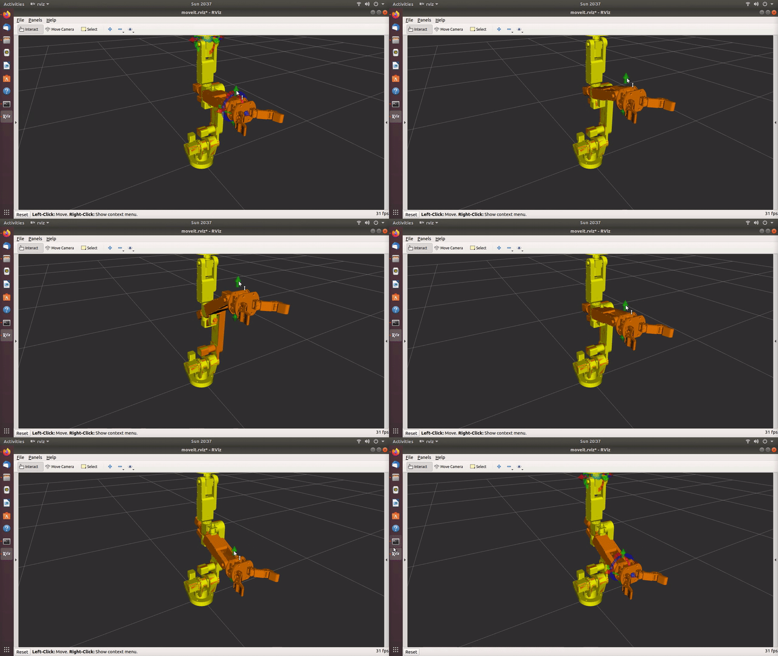
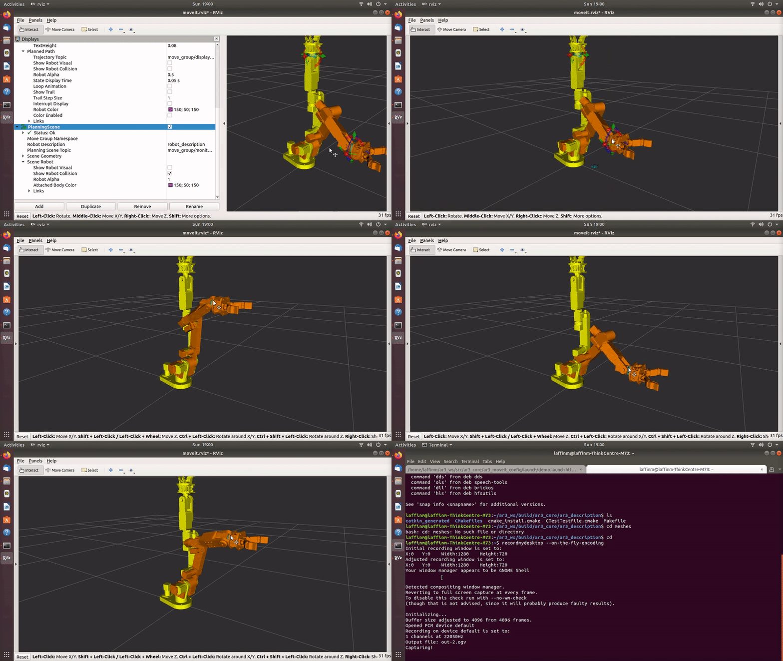
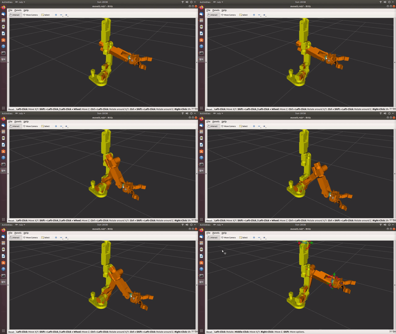
ROS functionality and simulation with ros_control and Moveit
04/04/2022 at 14:53 • 0 comments![]()
![]()
![]()
-
Two-Finger Gripper
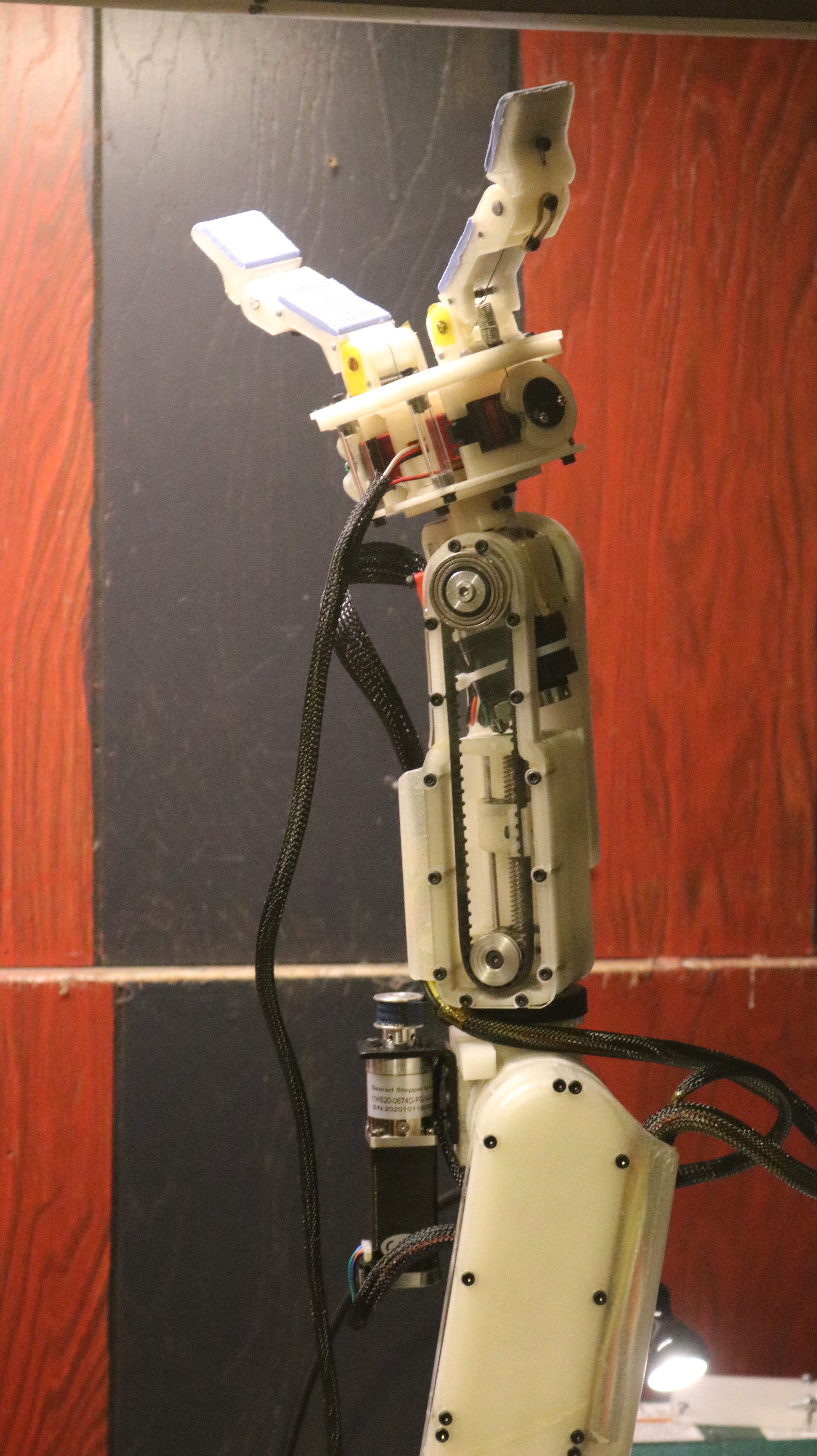
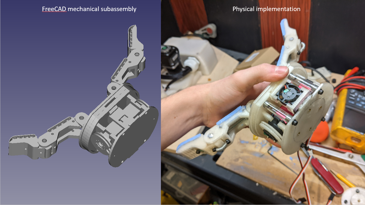
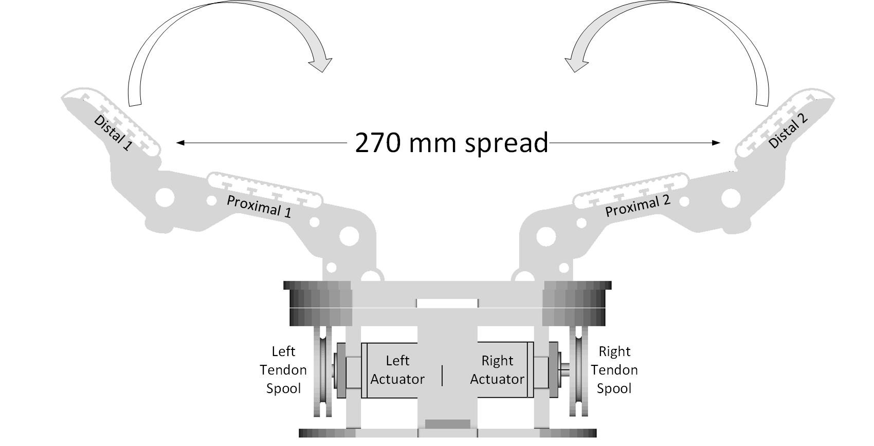
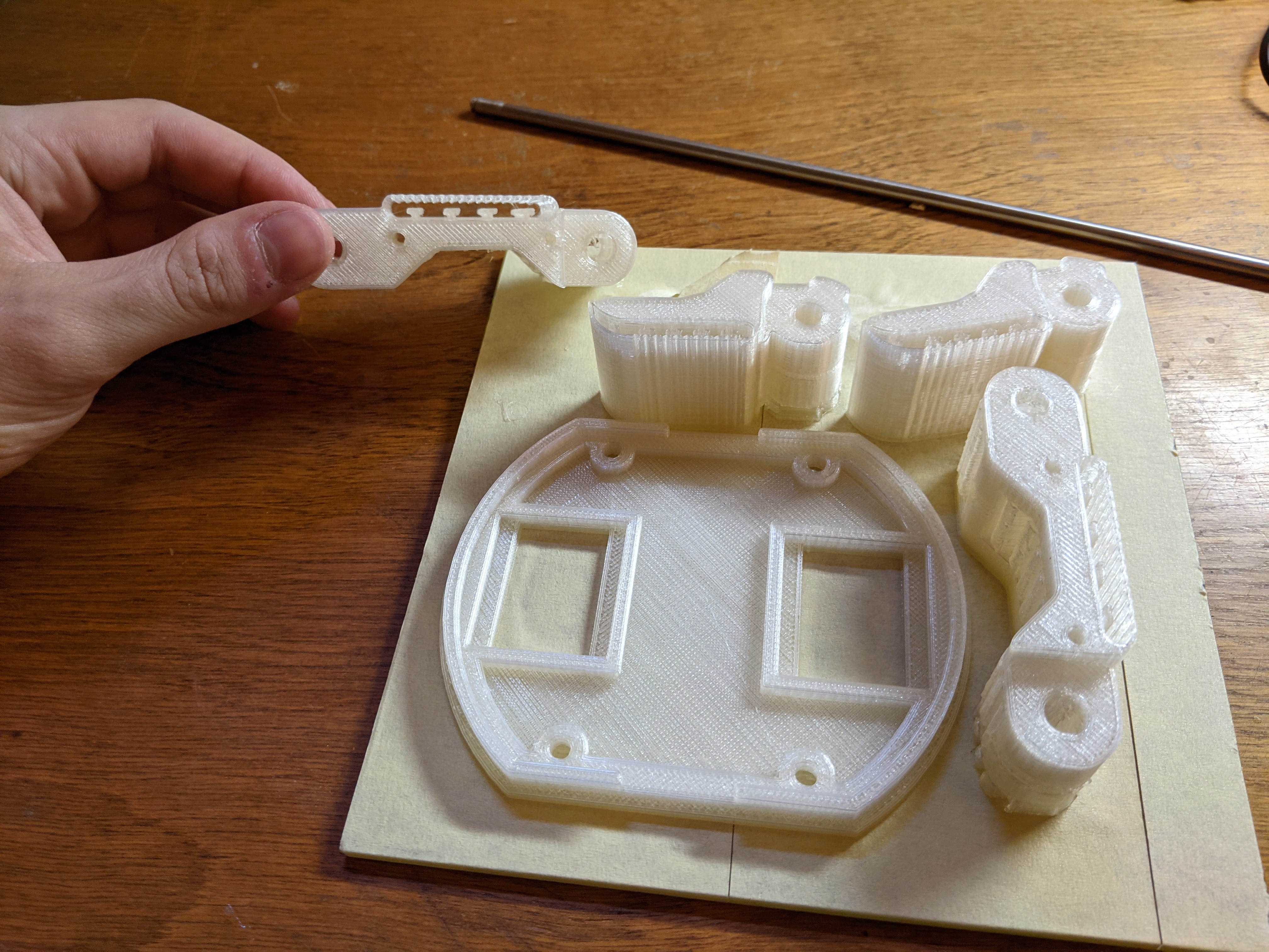
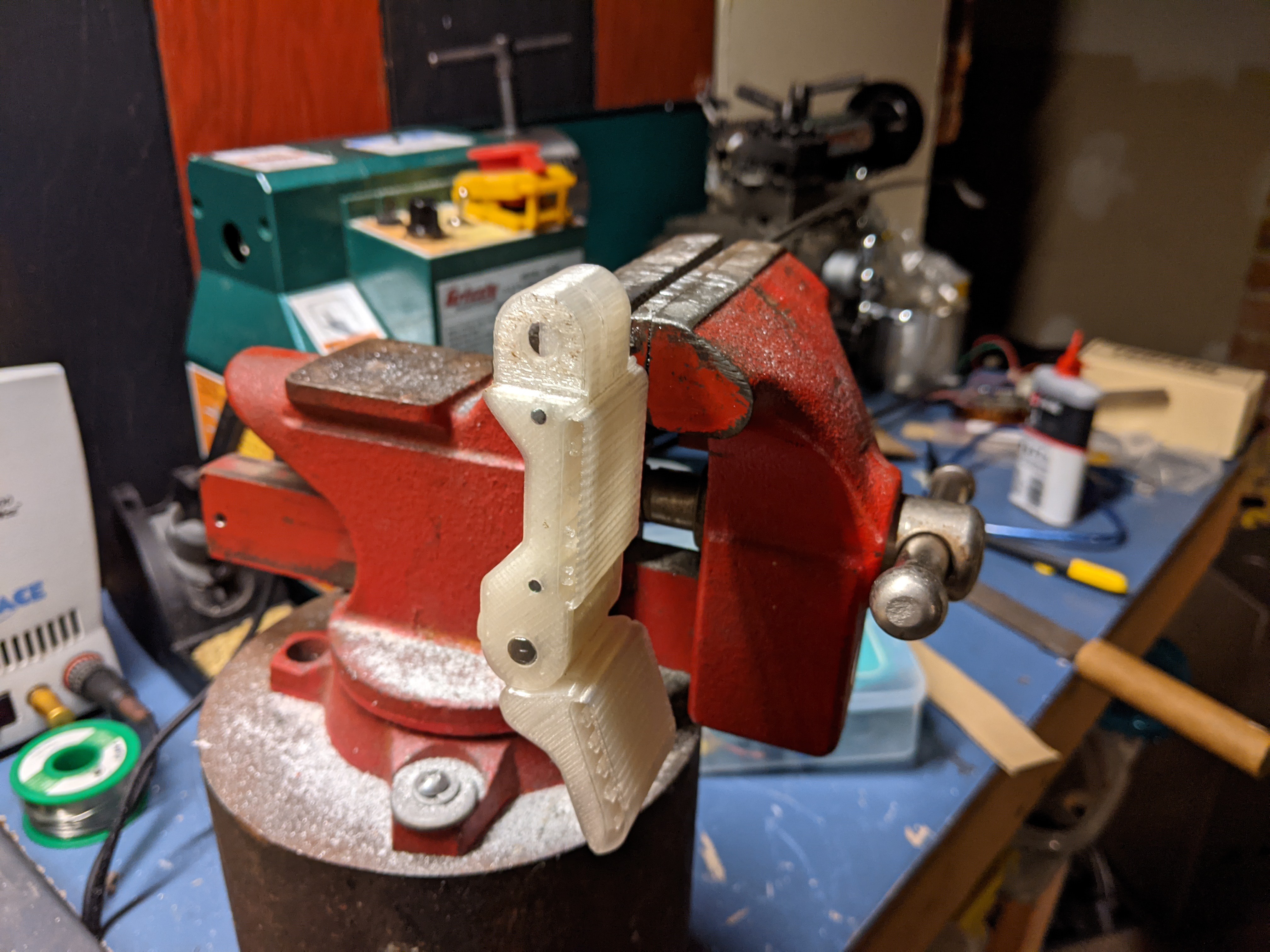
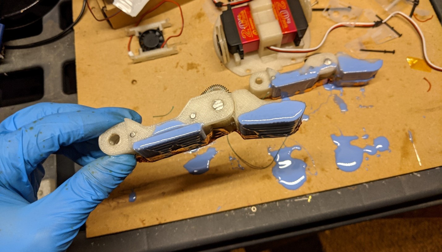
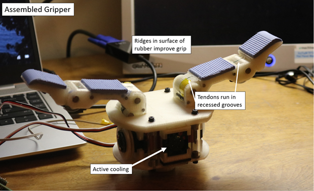
11/16/2021 at 19:23 • 0 commentsThis gripper is based on the Yale OpenHand research, and used a method of fabrication known as "hybrid deposition manufacturing" to produce a multi-material part which allows for superior grasping characteristics. The assembly consists of two fingers that are individually driven with 20kg servo motors. Each finger has two degrees of freedom, and is controlled by a single motor, making the device an underactuated system. Underactuated robotic hands show adaptive behavior that is allows for a wide range of objects to grasped.
![]()
![]()
![]()
![]()
![]()
-
Future Work
08/18/2021 at 16:35 • 0 commentsEnd Effector
-
Electronics enclosure
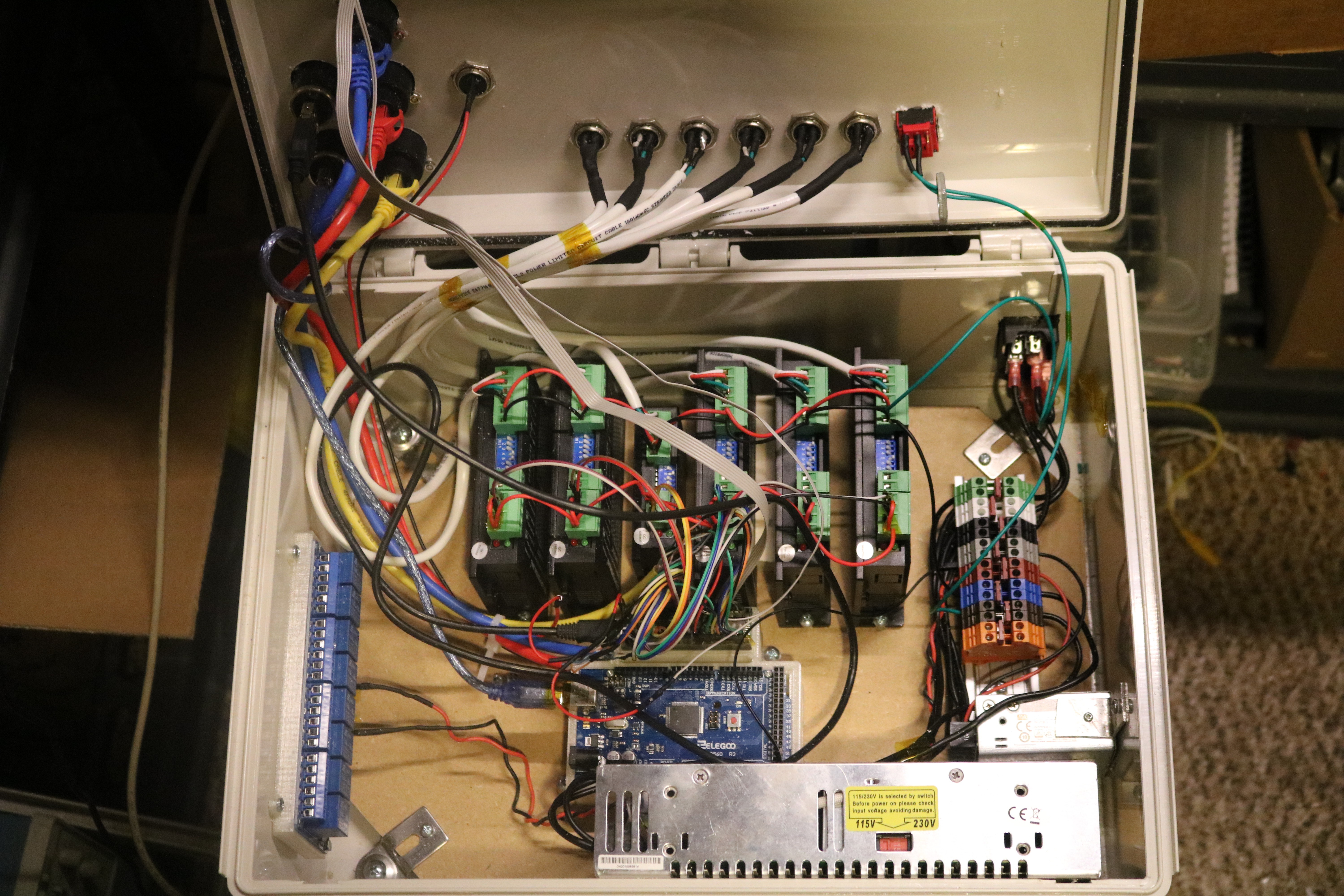
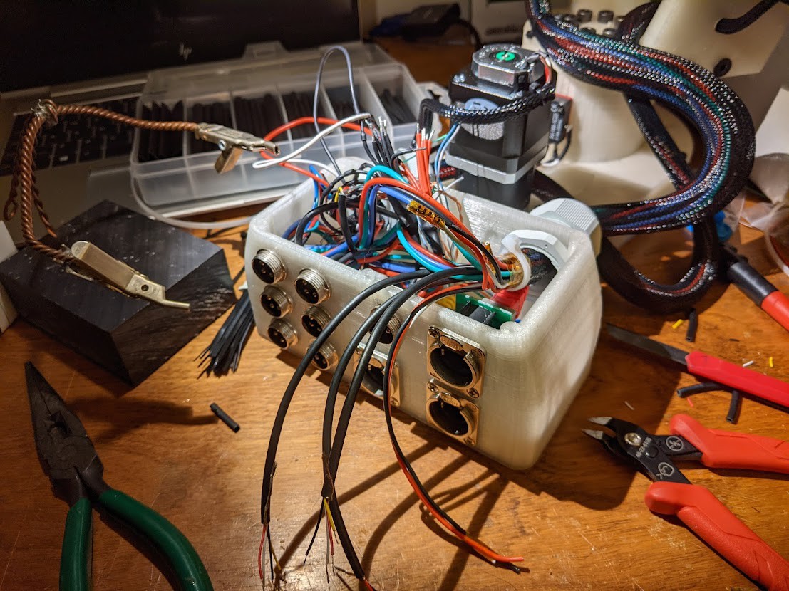
08/17/2021 at 19:04 • 0 commentsAn inside look at the controls enclosure. Mains voltage is fed in the right side inside the box and a DIN rail splits and connects two switched-mode power supplies. The larger supply on the bottom is 24V 10A for driving the stepper motors. The smaller power supply is located directly above and supplies 5V lines for the microcontrollers and accessories. The DM542T and DM320T drivers are mounted vertically (J6-left to J1-right).
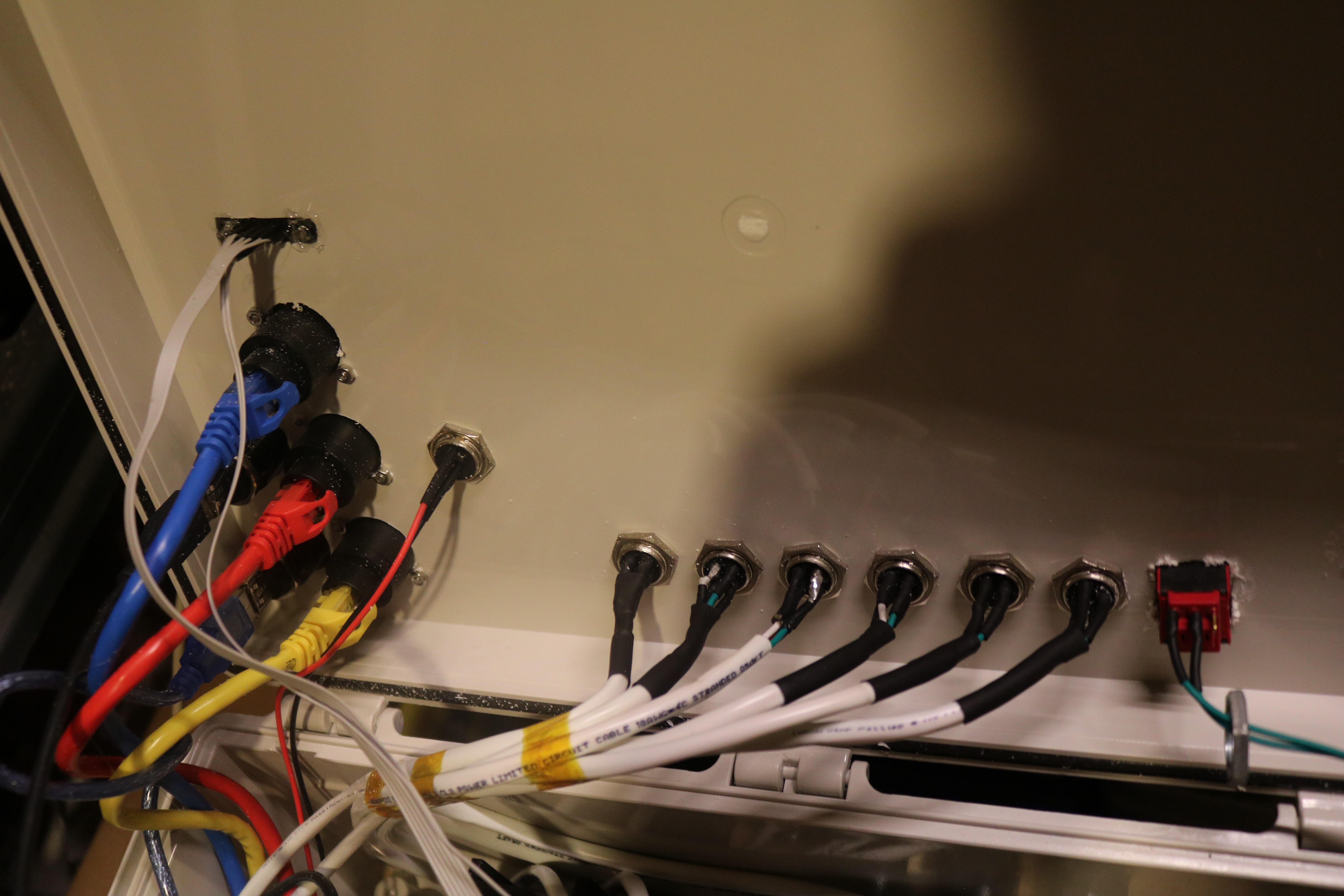
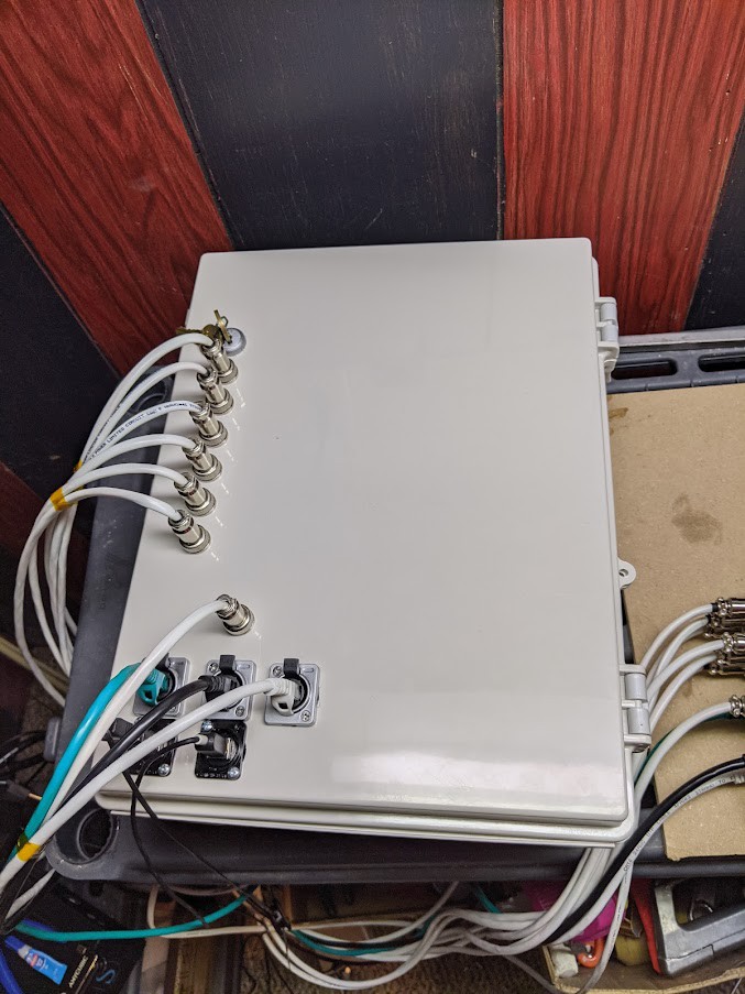
Close-up on the cable feedthroughs on the lid of the enclosure. The ribbon cable on the top left is for the controller arm, the CAT9 cables are used for high-speed encoder transmission, and the motor power cables are spaced horizontally on the bottom. On the far right there is an additional safety switch for the whole system.
An exterior view before the VGA port was added. I also ended up removing the key switch for a simpler rocker switch.
![]()
-
Software Development
08/15/2021 at 21:15 • 0 commentsTeensy Script
The current control scheme that I use to control the robot is very basic and uses the Arduino framework. I used the ubiquitous AccelStepper stepper control library which offers acceleration and deceleration functionality, as well as independent concurrent stepping with multiple motors (crucially important!). The pseudocode below explains the core process of stepping the motors concurrently.
loop()
{
     // Read analog value of each potentiometer
     targets = analogRead(SENSORS);

     // Assign a target value for the motors to step towards
     MOTORS.moveTo( targets * multipliers );

     // All motors perform a single step towards the target
     MOTORS.run();
}
Each loop iteration reads the position of all the sensors within the joystick, updates the target position for the steppers, and performs a single step towards it. Each of the stepper motor objects have different acceleration characteristics.
Additionally, the limit switches are configured as INPUT_PULLUP and prevent overextension on each joint.
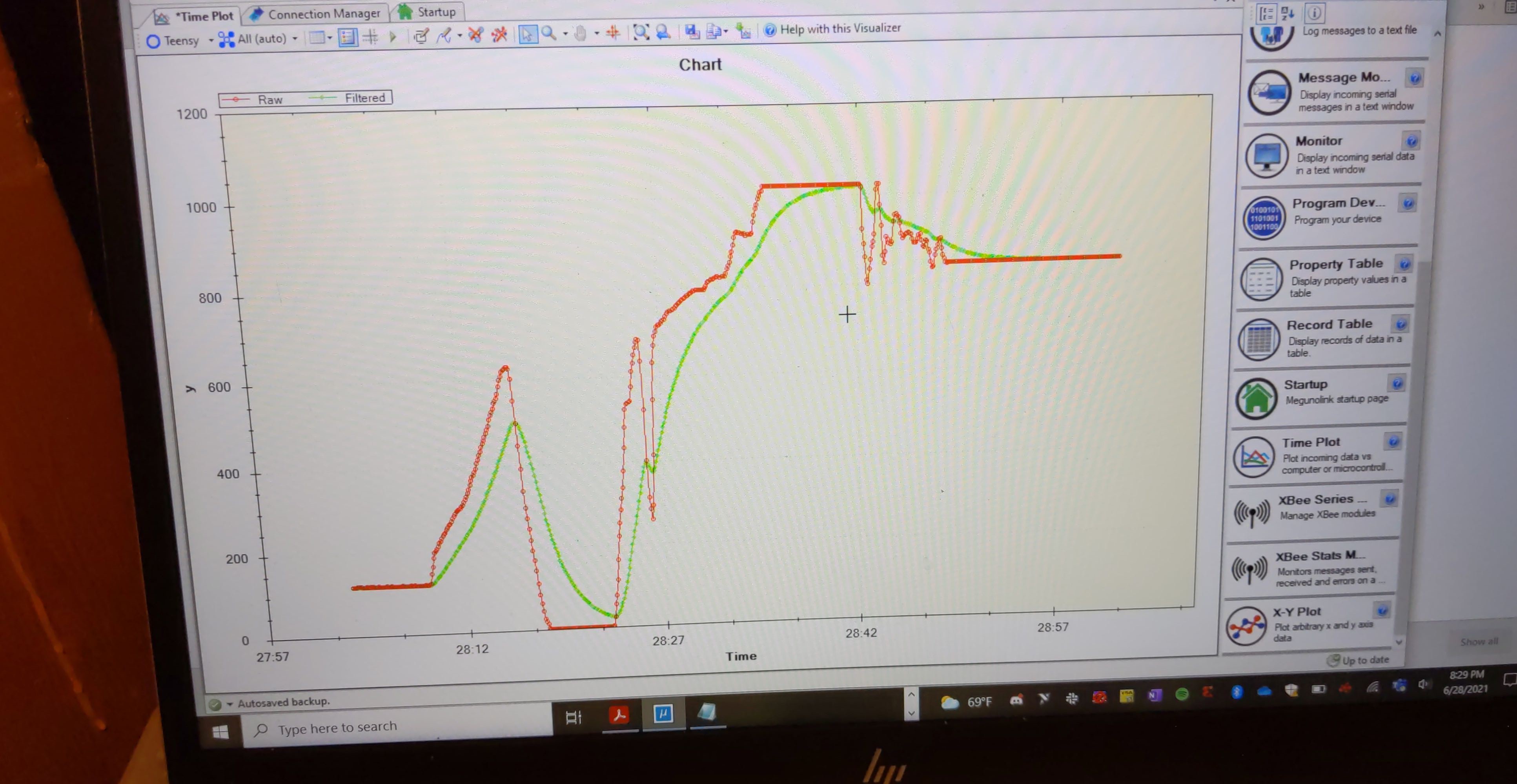
Filtering
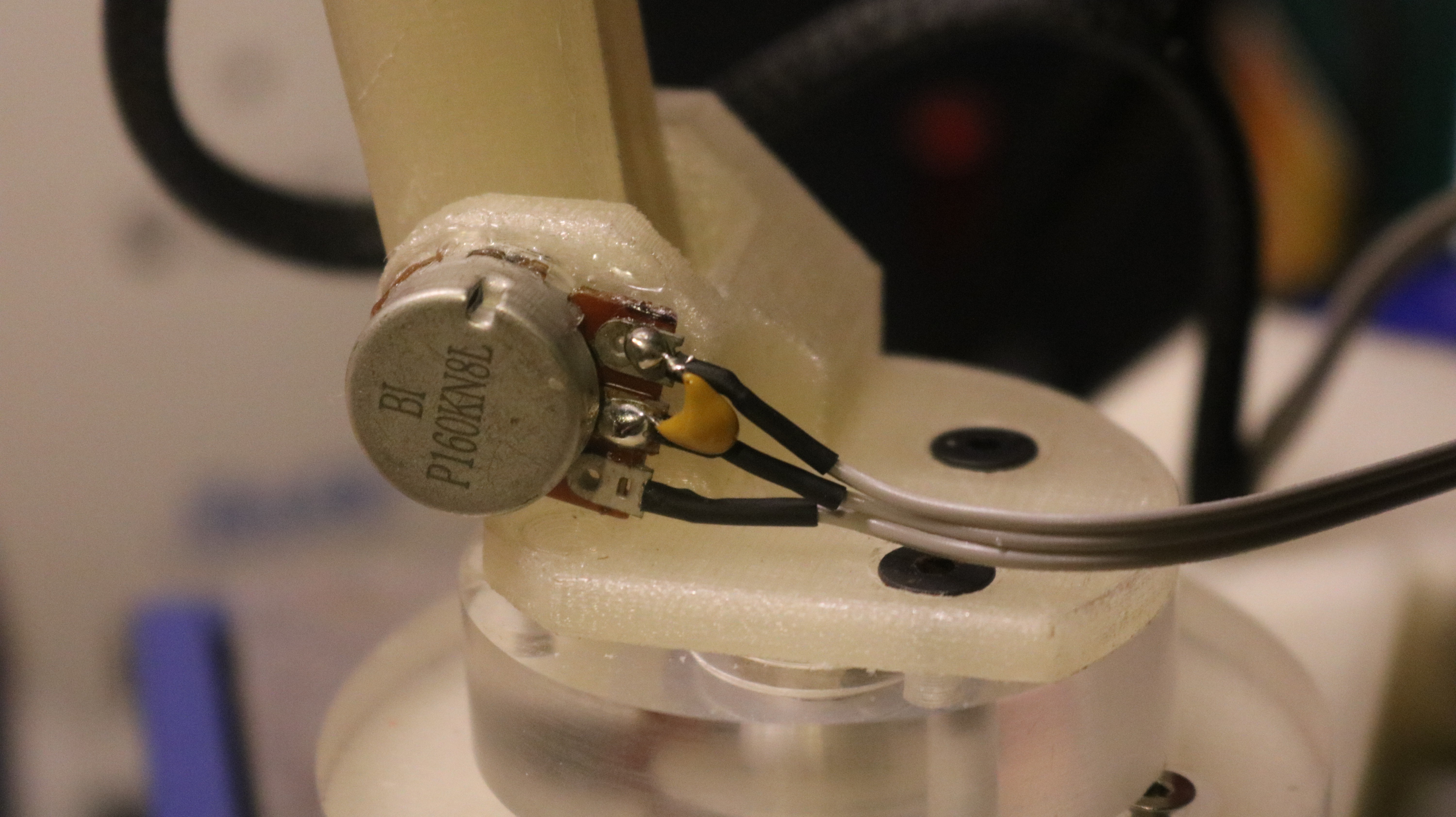
When using cheap components to drive large state changes within this system, it is important the the sensor readings are consistent and predictable. In this case, the analog voltage of the potentiometers in the controller arm are directly used to move joints quickly in an application involving close contact with people. The potentiometers I used are robust, but often noisy devices. To reduce jitter I added a 0.1 uF ceramic capacitor between the analog voltage and ground on each of the potentiometers in the controller arm. This creates a low-pass filter for the control signal.
Exponential smoothing in software
![]()
-
Designing controller arm
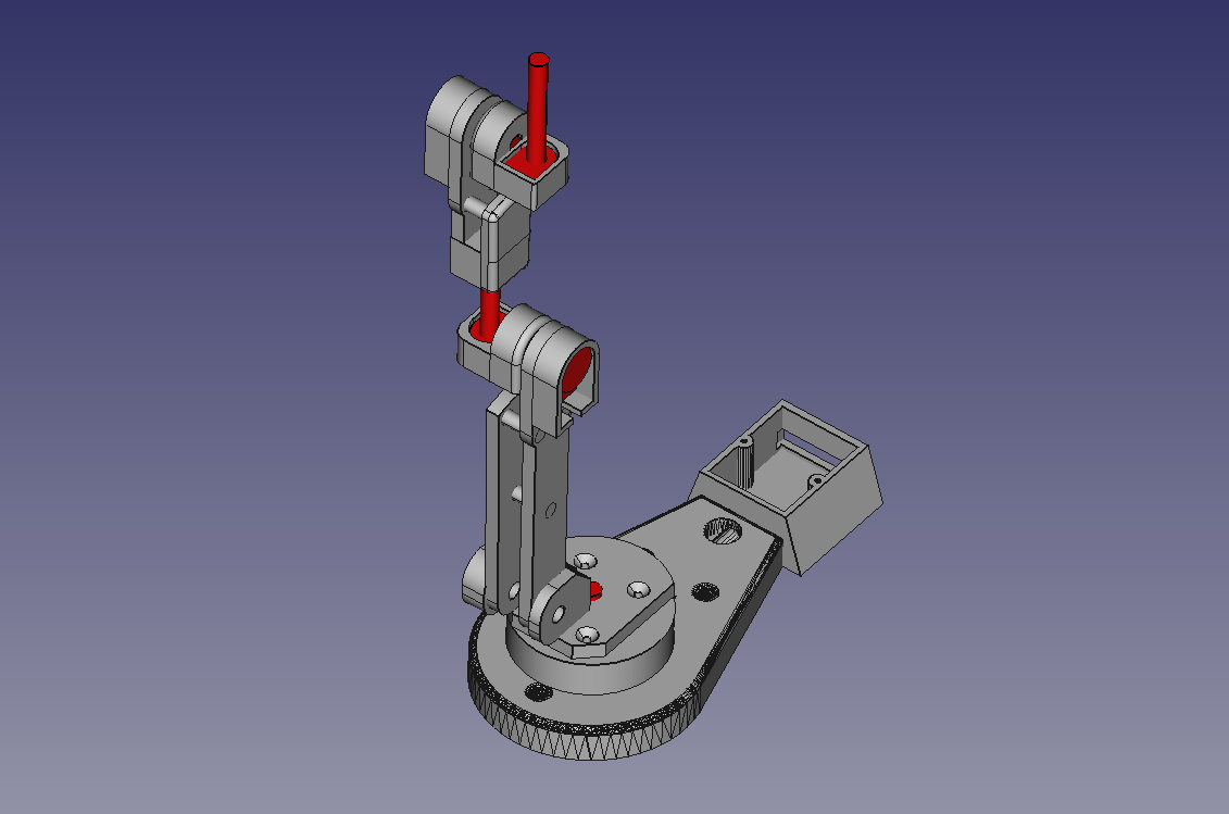
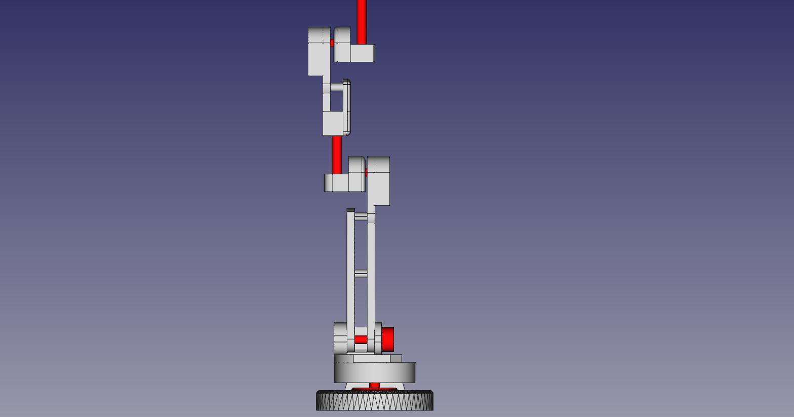
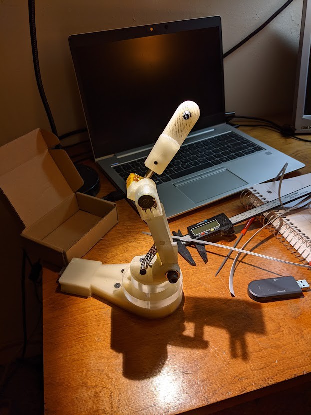
08/15/2021 at 21:00 • 0 commentsThe mechanical design of the controller arm assembly was done using the open source modeler FreeCAD. Although it may not appear similar, the structure is dimensionally congruent to the full robot arm. The potentiometers are shown in red to increase visibility, and printed components are shown in grey. Full CAD model is available here. To print individual components, simply select the part from the model list and export as an STL to be printed.
![]()
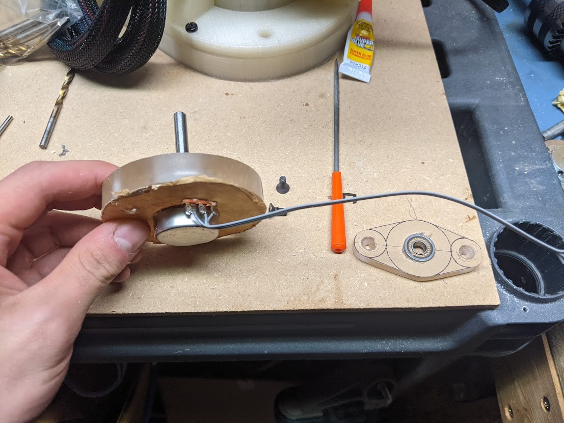
The spacer plate shown below was machined out of polycarbonate, however it could be printed in PLA just as effectively as the other parts. The J1 potentiometer shown below was eventually replaced with this component. Both of these are overkill electronics for this application, but when using the shaft directly in the joint I primarily want a mechanically robust part.
![]()
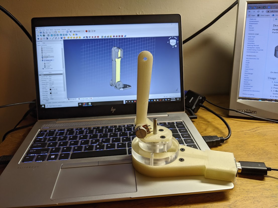
Beginning the design of the arm. The methodology that I used was to basically design the most minimal solution, and then immediately print and test the operation. After several iterations I could usually move on to the next joint within the arm with reasonable confidence. I still want to modify several parts of the design to control joint stiffness on J3 and J1.
![]()
Mechanical progress up to the J3 hinge. You can see how I threaded the wires for J1 through the base. A hole was later drilled into the base to allow wires from the other potentiometers into the rear of the wire housing.
![]()
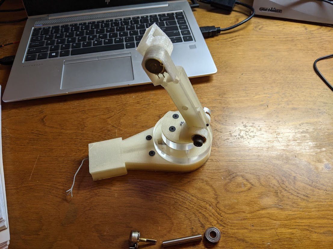
J4 hinge completed. I added a set screw to allow for vertical adjustment on the J4 link. For most joints the controller has a larger range of motion than the actual robot arm, but this can be compensated for in software.
![]()
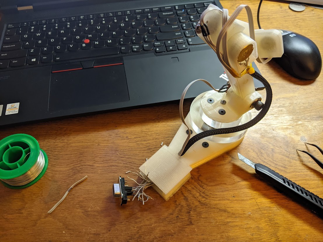
Soldering ribbon cable to the VGA connector in the base of the controller. I decided to use this connector simply because it contains a sufficient number of conductors, and I had several on hand already. Each conductor is marked with tics from a Sharpie, and heat shrink tubing is used to insulate.
![]()
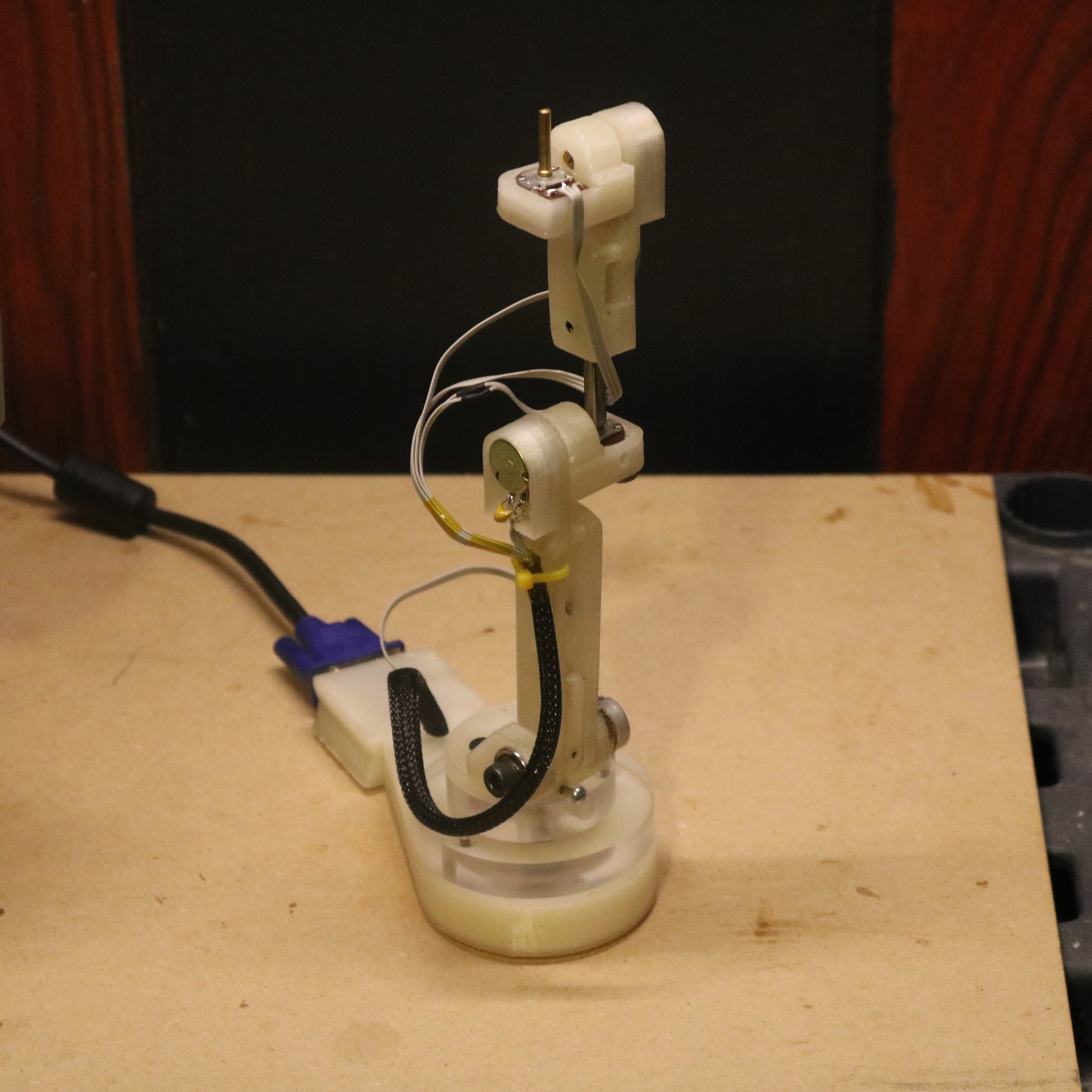
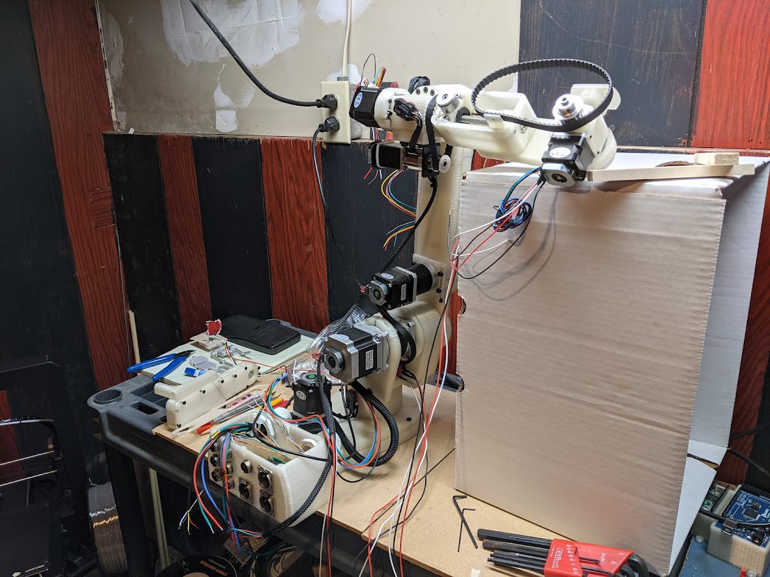
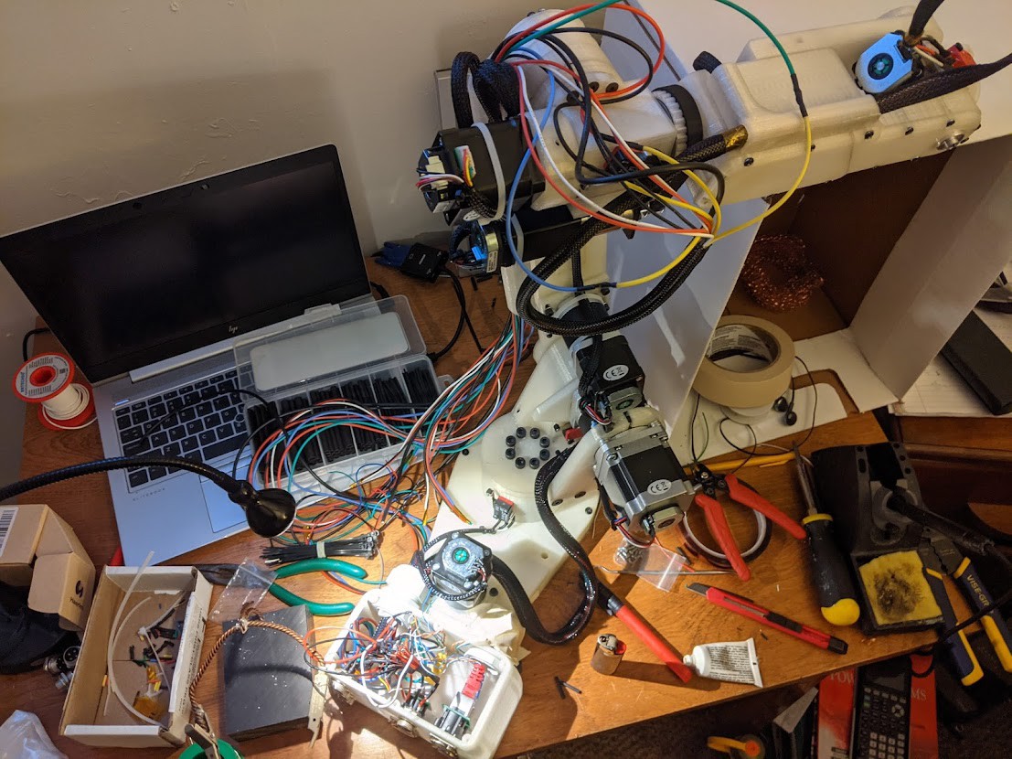
Functional arm shown below. The ribbon cables were grouped together using kapton tape and 1/4" plastic wiring harness. Ideally all of these cables could be harnessed within the body of the arm to reduce clutter in the final product.
![]()
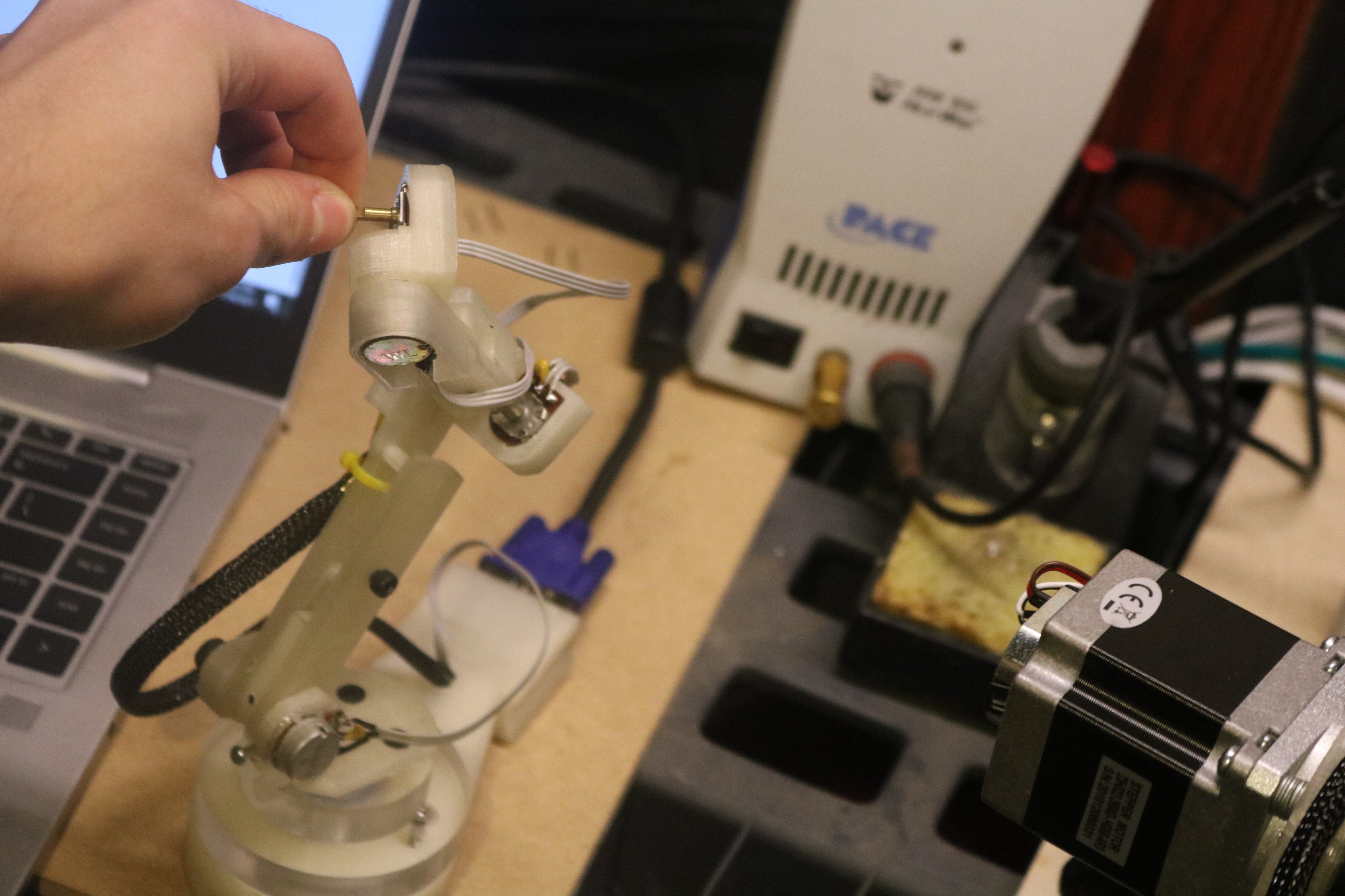
Initial testing of full controller arm. The J6 potentiometer shaft has six degrees of freedom and can move in any position within the range of the arm.
-
Prototyping the Robot Arm
08/15/2021 at 00:20 • 0 commentsPrinting Structural Components + Covers/Spacers
All printed components in this system are PLA, and are printed at 100% infill. Everything was printed on my old da Vinci Junior 1.0.
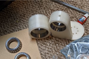
Setting tapered roller bearing seats into the J1 and J2 turret housings.
![]()
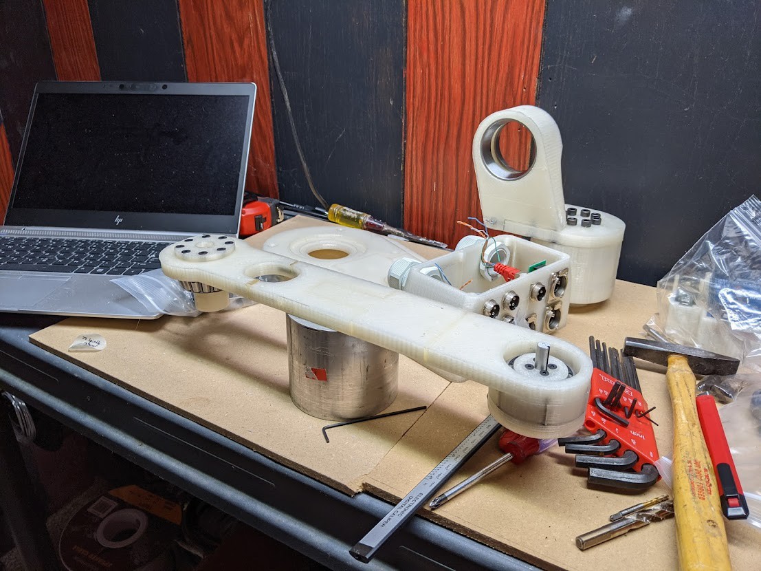
Initial progress on the first version of the J2 arm with spindle and roller bearing installed on the left side. On the right side the J3 bearing assembly is finished, with spindle and retainer installed. To note, I've tested printing the J3 bearing cup at a lower infill, to act as an intentional break-point in the event of a collision. Ultimately this entire arm is replaced with a solid polycarbonate plate, and the spindle retainer was eventually remade in aluminum.
![]()
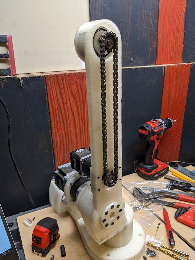
J3 chain installed and tensioned. This can be seen even with the cover on in the final design! All the extra work involved in adding a chain and sprocket drive is simply to lower the mass of the J3 motor towards the base of the arm. Even though it would be much simpler to manufacture, direct driving this joint would extend the mass of the arm and involve much larger forces on the lower joints when moving.
![]()
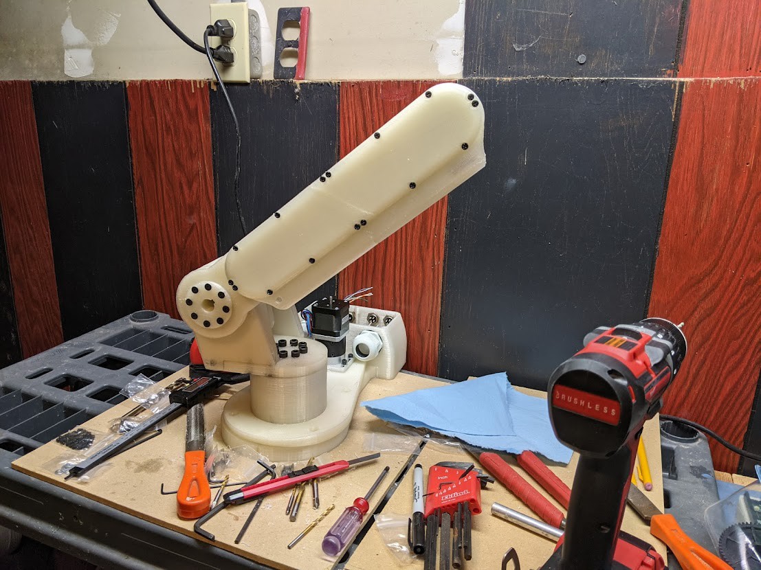
The chain and sprockets are lubricated with lithium grease. Below the cover for the J2 Arm installed. The rear side contains a rigid wire harness to contain slack from the additional motors.
![]()
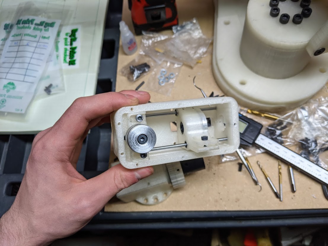
Initial work on the J5 lower assembly. The J5 motor shaft has a 200mm lead screw which drives the inner carriage back and forth on 3mm linear rods and bearings. Alignment of these components is critical, and took several attempts to get proper results.
![]()
Below the J4 turret housing is installed perpendicular to the J3 spindle. I had pressed a needle roller bearing inside and installed the J4 shaft. The J4 timing hub is also fixed to the shaft, along with the J5 motor mount and associated thrust bearings and washers. At this moment I was installing the J5 lower assembly.
![]()
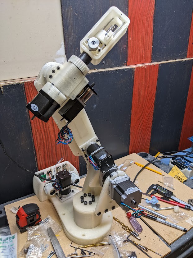
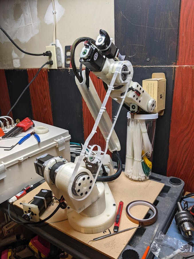
Another progress photo, now showing the J4 timing belt installed and tensioned. The J5 upper bearing arm is bolted to the J5 lower assembly. The J6 housing and spindle holds the 6th axis stepper motor, and is held captive to the J5 bearing arm via tapered roller bearing and cap with thrust needle-roller bearing and washers.
The 150XL timing belt used is fixed to the J5 carriage clamp, and tensioned between the 15XL pulley and idler post on the J5 lower assembly. The rotation of the J5 shaft shaft (lead screw) drives the carriage clamp back and forth within the assembly, driving
![]()
![]()
![]()
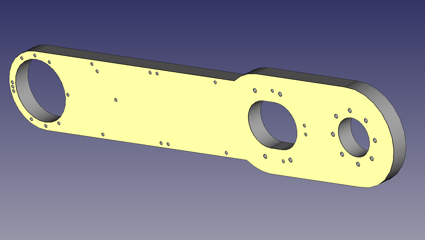
J2 Redesign (above) and fabricated part made from polycarbonate plate (below).
![]()
![]()
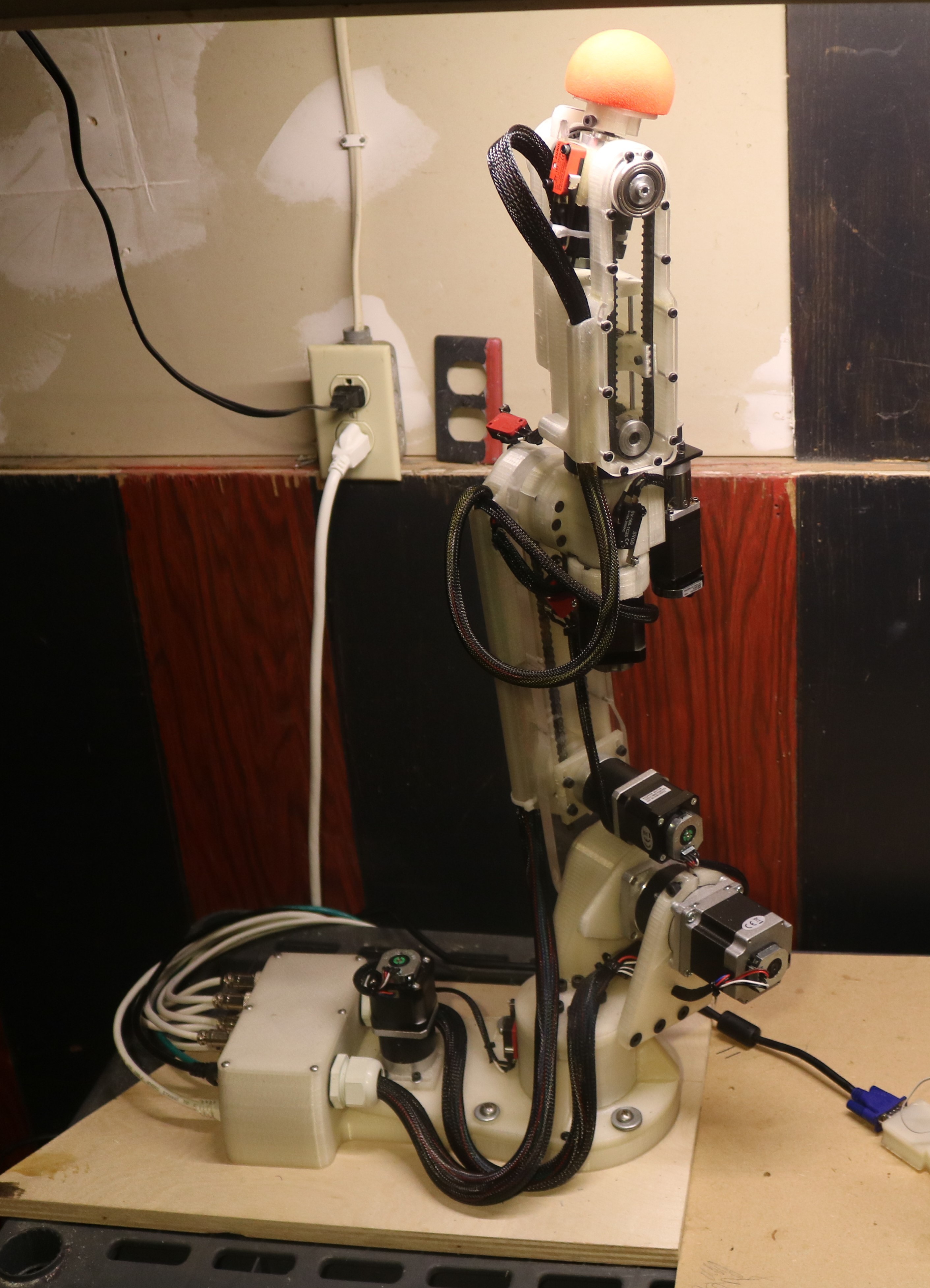
Assistive Robotic Manipulator and 6-DoF Controller
A low-cost, 3D printable assistive robotic arm prototype for individuals with limited upper limb mobility.
 Michael Laffin