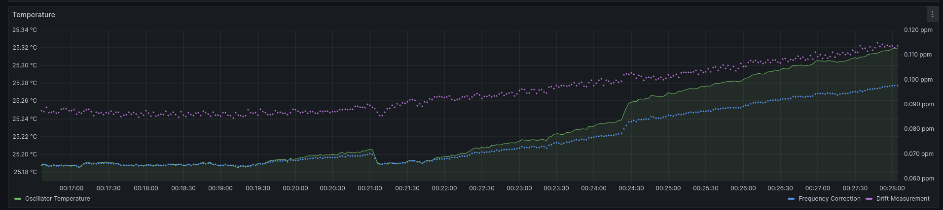
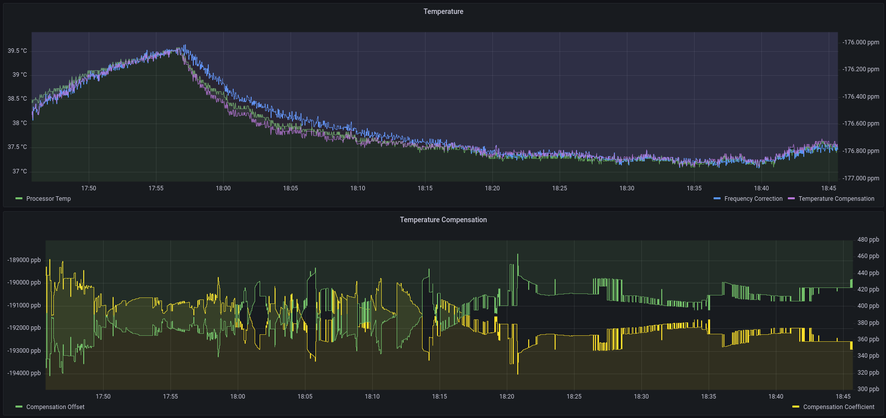
The MAX6577 temperature sensor appears to exhibit both Gaussian and burst noise. The Gaussian noise is desirable since it improves the temperature measurement precision with appropriate filtering, but the burst noise is slightly problematic. The burst noise produces abrupt 10 mC to 20 mC steps in the temperature measurement which result in 2 ppb to 5 ppb perturbations of the frequency correction. These perturbations produce bursts of minor offset drift.
These sudden shifts need to be mitigated to reduce tracking error in NTP and PTP clients.
I've replaced the internal crystal oscillator and temperature sensor with an external oscillator and analog temperature sensor. This provides both better precision for temperature measurements as well as tighter thermal coupling between the oscillator and the temperature sensor.
Oscillator: ASE-25.000MHZ-L-C-T
Temperature: MAX6577ZUT+T
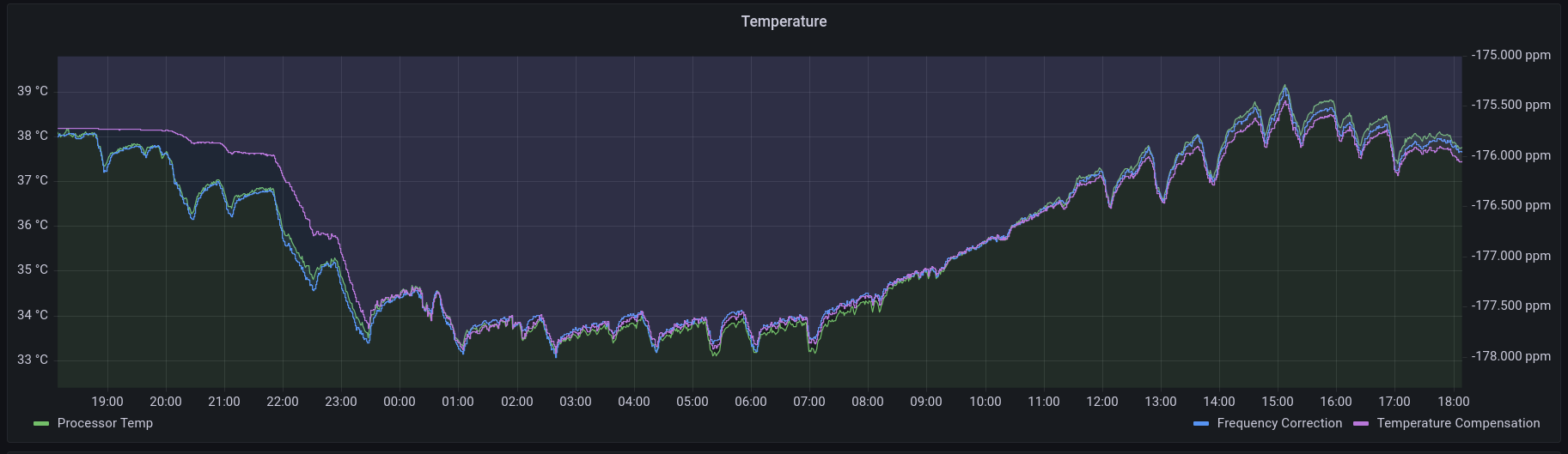
The frequency output of the MAX6577 provides better than 0.01 C precision when combined with 32-bit timer capture. This allows for a PPS RMS tracking error of less than 10 ns.
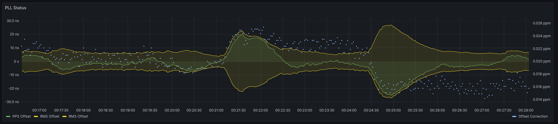
I've successfully synchronized an embedded PTP client with the GPS time server. I still need to verify that I'm correctly setting some of the protocol fields, but I've otherwise managed to get +/- 100ns tracking over a single switch hop using the IEEE 802.1AS gPTP profile. The gPTP profile uses raw ethernet frame encapsulation with the 0x88F7 ether type. I decided to use this particular profile since it provides a simple zeroconf style configuration.
On the client side, I've implemented the offset tracking as 1 Hz update process with three stages:
Collect the sync samples from all active sources in a single ring buffer.
Only retain the N most recent samples that fall within the current one second interval.
Perform a linear fit of the collected offset samples vs their arrival time after excluding 2-sigma outliers.
Supply the predicted current offset to the tracking PLL.
Update the frequency drift filter.
Update frequency correction using 2-sigma filtered mean.
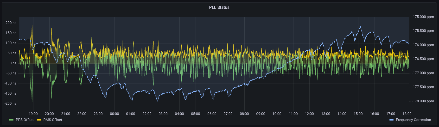
The result is a surprisingly clean and consistent offset tracking error.
Since I've now confirmed that this time keeping approach works, I plan to focus on completing the board layout so I can order prototypes and finalize the hardware design.
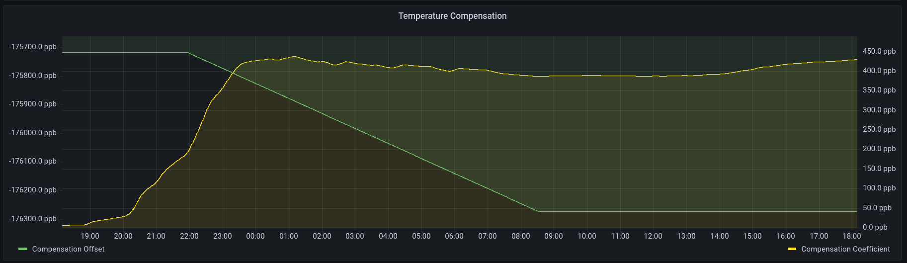
I've rewritten the frequency and offset correction code to be entirely digital and restructured the system clock to be a three layer structure with a free-running monotonic timescale, a frequency disciplined timescale, and an offset disciplined timescale. The three-layer clock allows for independent disciplining of frequency and timing offset and improves overall tracking accuracy. The system is now capable of frequency steering with a resolution of 0.232 ppb.
In addition, I've restructured the GPSDO and NTP code into a single unit to make GPS/NTP fail-over more seamless and improve code reuse. NTP source selection and health tests are still a WIP, but I've also implement support for select chronyc queries:
sources
sourcestats
ntpdata
tracking
This allows for viewing fairly detailed status information with the chronyc utilty.
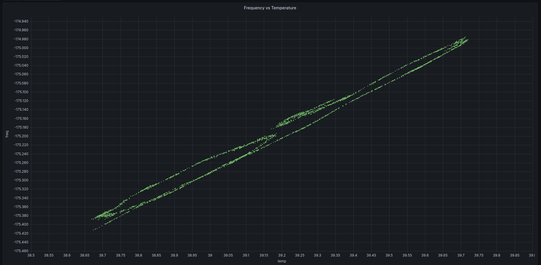
A large benefit of this massive rewrite is that the frequency error measurement is now both precise and accurate enough to expose the presence of hysteresis loops in the tracking error. Further analysis is needed to isolate the cause, but they still make some interesting patterns. The loop widths are less than 30ppb, and they were previously buried in the measurement noise.
After exhaustively comparing the datasheets and performing software tests on different eval boards, it's become clear to me that these two parts are functionally identical down to the pinout, register map, and address map. The only difference I've been able to find is the onboard ROM.
Thankfully, since I'm not using the ROM, I can use these parts interchangeably which makes sourcing them significantly easier.
I've implemented SNMP and the GPSDO logic. The software is currently using the frequency trimming support in the PTP hardware to under-clock the PPS and steer the edge alignment. Otherwise, the temperature compensation and PLL logic are working as expected. I still need to make a breakout board for the DXCO and I2C temperature sensor.
I've decided to modify the design to use the TM4C1294 series MCU. It has essentially the same feature as the MSP432, but with a higher clock speed and it is currently in-stock at multiple suppliers.
The CPU clock speed is nominally rated for 120MHz, but I have so far seen no issues overclocking it to 125 MHz to get a clean 8ns of timer resolution. The 32-bit timers also seem to have no issue operating at 125 MHz.
I've added an e-ink display to the design for debug and status purposes, and also implemented DHCP and NTP.
I've been using an EK-TM4C1294XL eval board for prototyping. I'm currently working on an eval board layout for the DCXO and temperature sensor. The GPS eval board should be arriving sometime next week.
 These sudden shifts need to be mitigated to reduce tracking error in NTP and PTP clients.
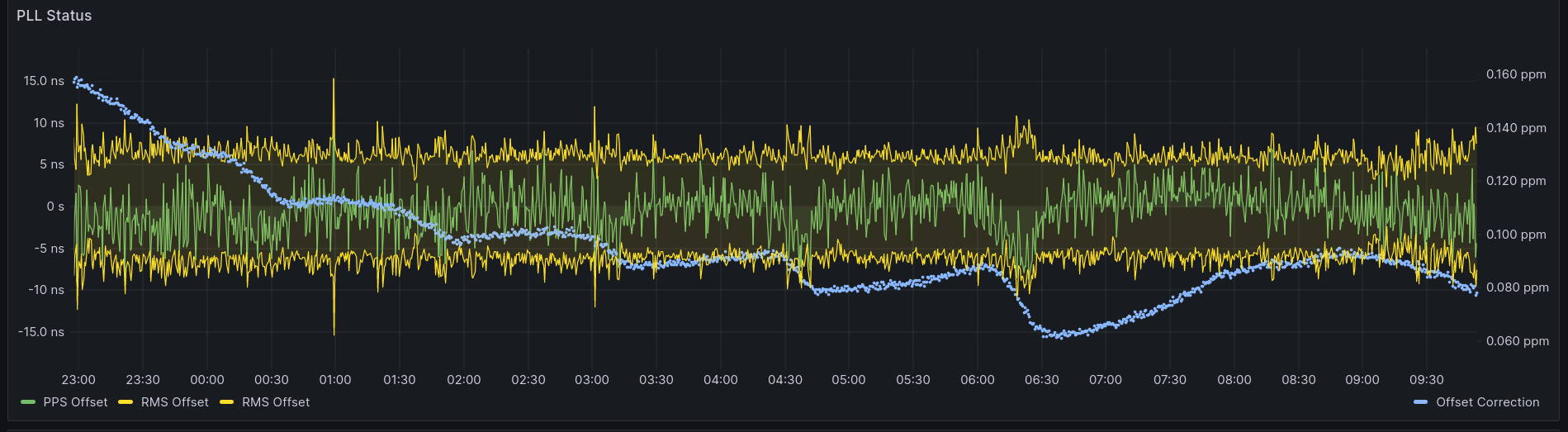
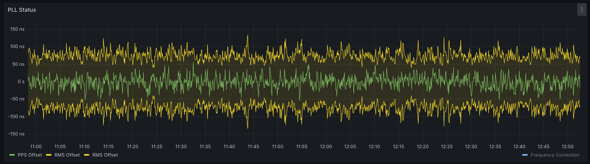
 PPS Tracking:
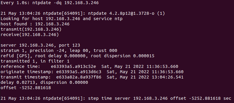
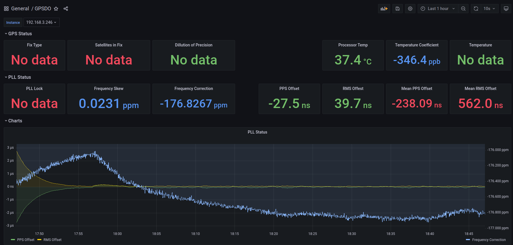 Comparison against GPS NTP server:
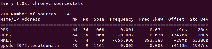
 I've been using an EK-TM4C1294XL eval board for prototyping. I'm currently working on an eval board layout for the DCXO and temperature sensor. The GPS eval board should be arriving sometime next week.