Firmware
The heart of this minimalist clock is the zero error Bresenham algorithm. It uses the Timer 0 to generate an interrupt at every 256 machine cycles. At every interrupt an accumulator is added by 256 up to the point where it overflows the amount of machine cycles in 1 second (Fclock/4 or 2000000). Every time the overflow occurs, the clock advances 1 second, and since such value is not divisible by 256, the difference is kept to be added to the next cycle. The side effect is that the 1 second interval have some jitter, but it is not even noticed, as the clock itself counts up every 60 seconds, or 1 minute.
static void irqHandler(void) __interrupt 0 {
    // gets here every TMR0 int (every 256 ticks)
    bres+=256;
    if (bres>=2000000) // 8MHz cpu = 2000000 cycles per second
    {
        bres=bres-2000000;
        advanceSeconds();
    }
...
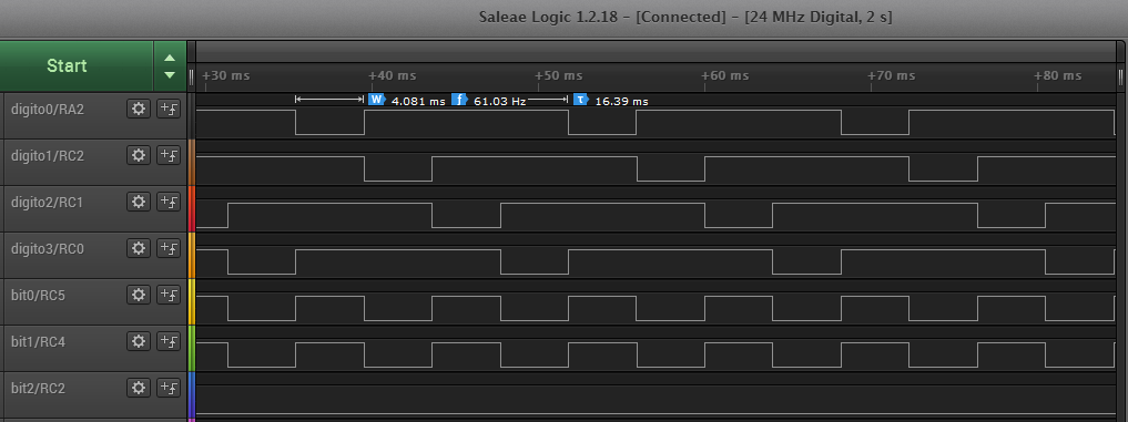
The interrupt routine also increments another counter which is rounded at every 32 counts to generate the timebase for the main function to run at approximately 4ms, which is also the maximum amount of time that every "digit" stays lit. The tickCounter is also used to form a rudimentary PWM, with 32 steps that is used to control the brightness of the LEDs
    tickCounter++;
    tickCounter &= 31;
    if (tickCounter == 0)
       go=1; // ~4ms per digit
    else if (tickCounter == tOFF ) {   // rudimentary PWM
       RA2=1;                          // Turns off all displays before
       RC2=1;                          // the next cycle
       RC1=1;
       RC0=1;
The firmware is developed in SDCC, and a makefile is provided.
Circuit
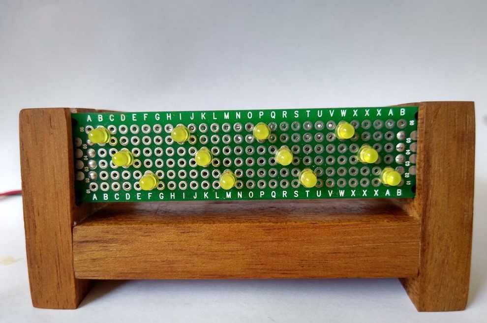
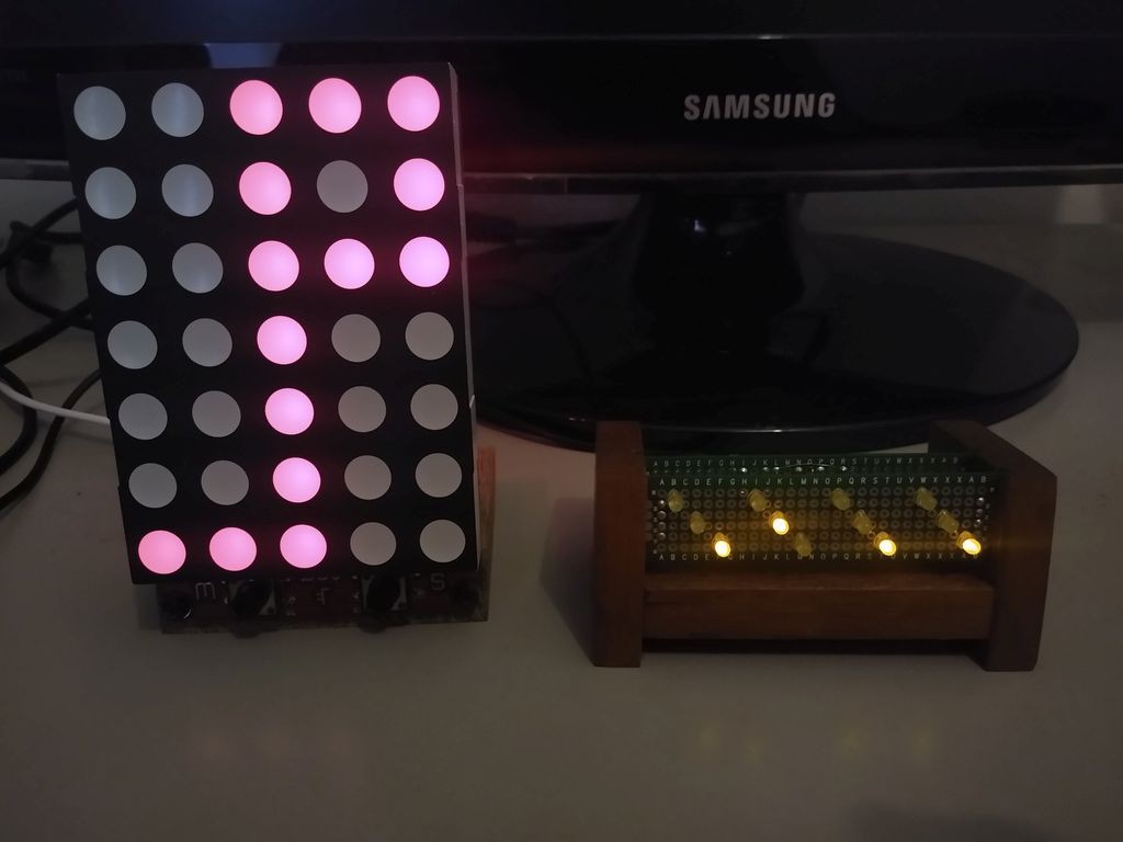
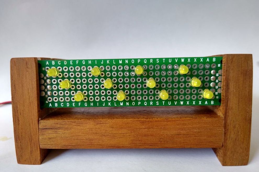
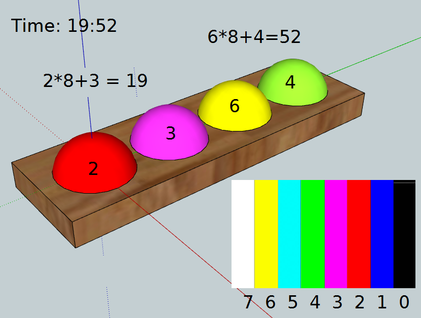
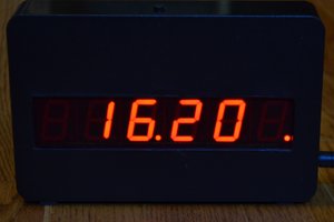
The Display consists of a matrix of four octal "digits" with 3 bits each.
Every time the main program run one of the digits is selected. As we have ~4ms for each LED the overall display rate for the whole display is around 16ms or ~60Hz.
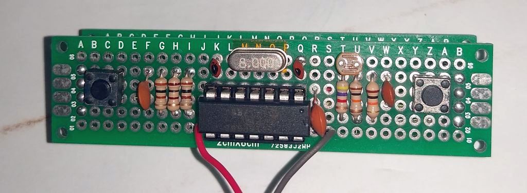
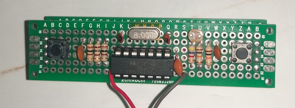
The circuit provides an LDR for sensing the ambient light. A couple of resistors is used along with the LDR to condition the signal on a range from approximately 85 counts in the dark to 150 counts with the lights on. Such value is used to calculate the variable tOFF which controls the duty cycle that every digit is kept active.
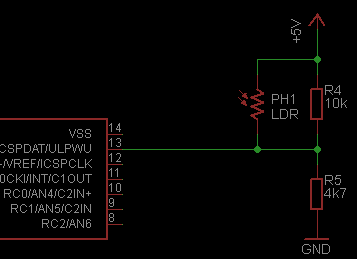
On Light ambient every digit stays lit for the whole 4ms (32 out of 32 counts).
And on dark ambient every display is lit at only 1 out of 32 counts

The circuit provides two tactile switches for adjusting the time. One advances the hours and another advances de minutes. The de-bouncing of the keys is performed mainly by software, but some tactile switches can be very noisy, thus a capacitor of 10nf was used to enhance the de-bouncing.
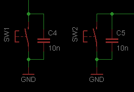
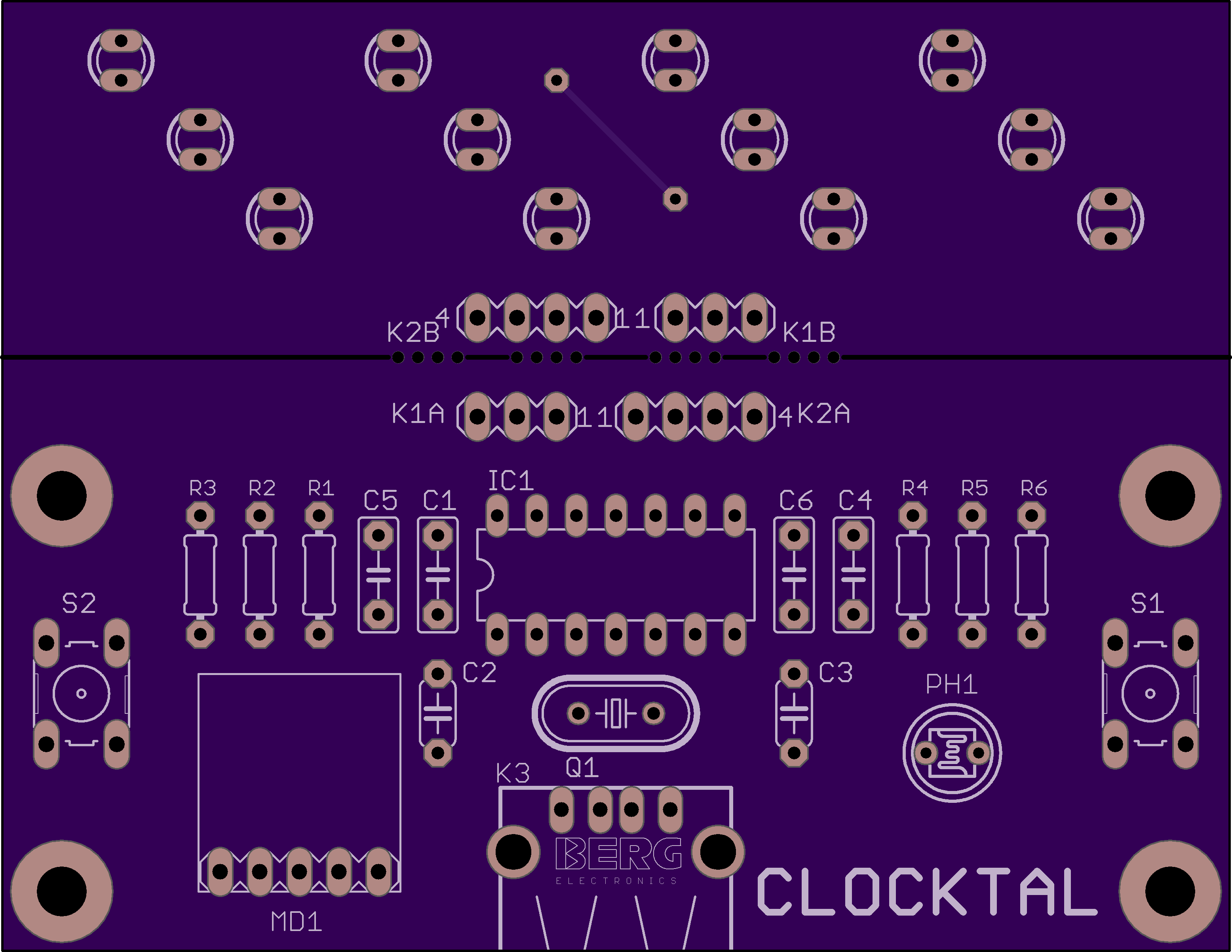
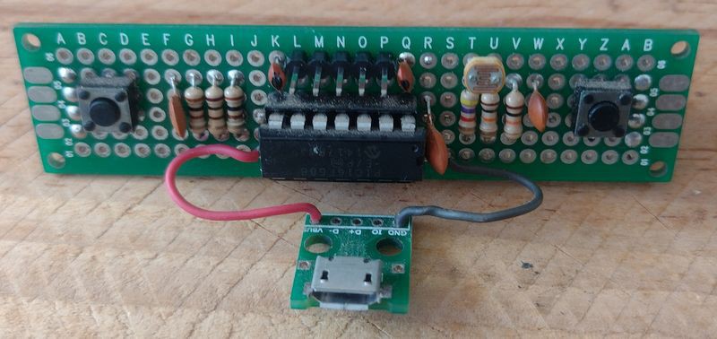
The whole circuit can be seen below.

Assembly
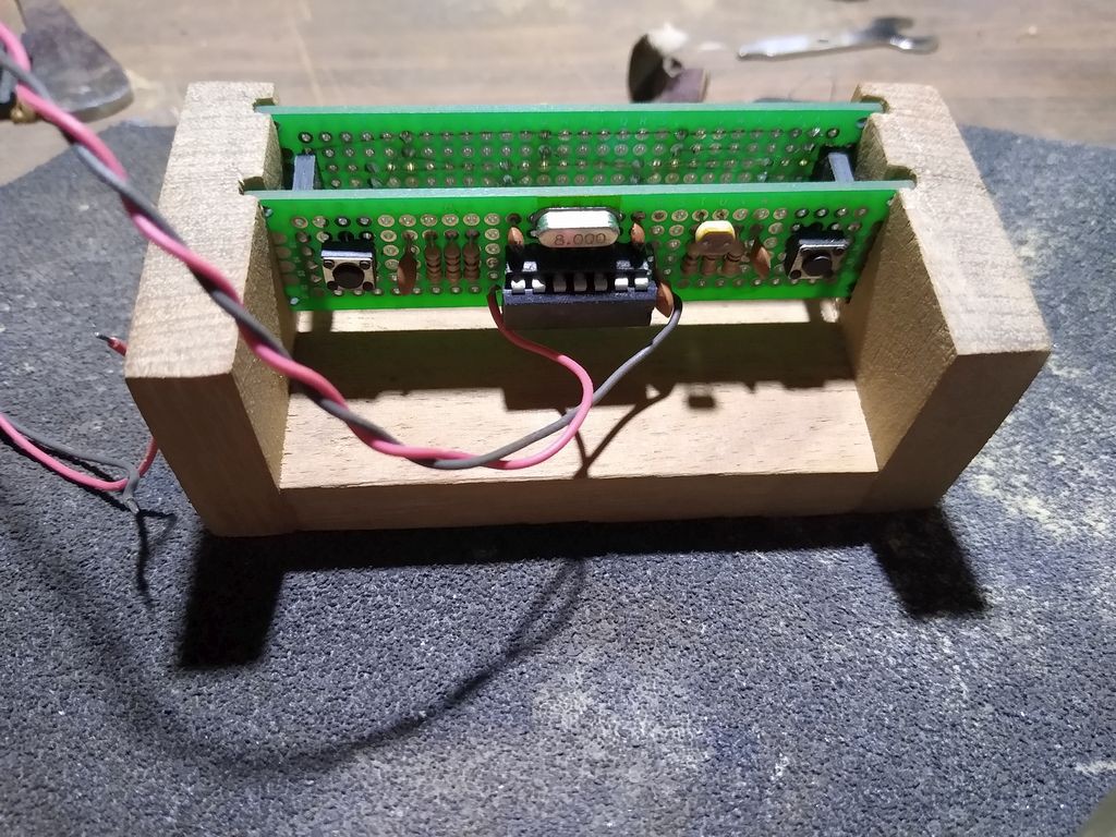
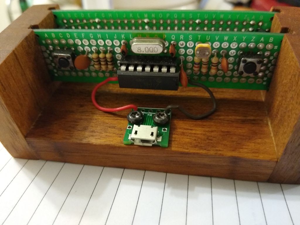
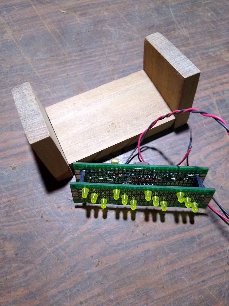
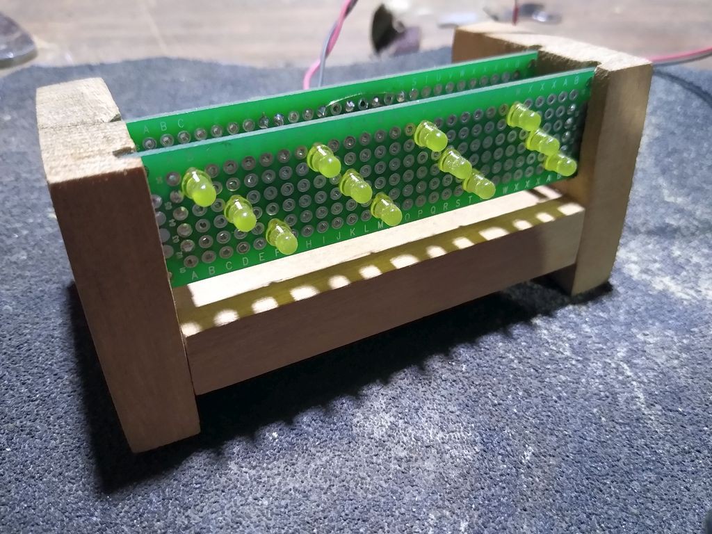
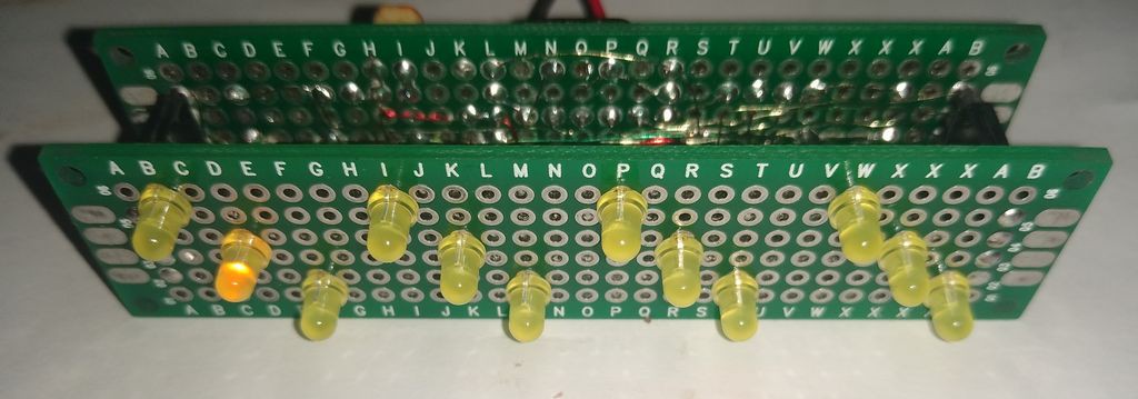
The circuit is being assembled on a pair of 2x8 cm perf-boards.
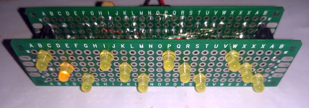
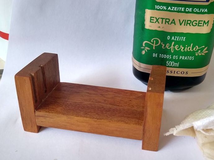
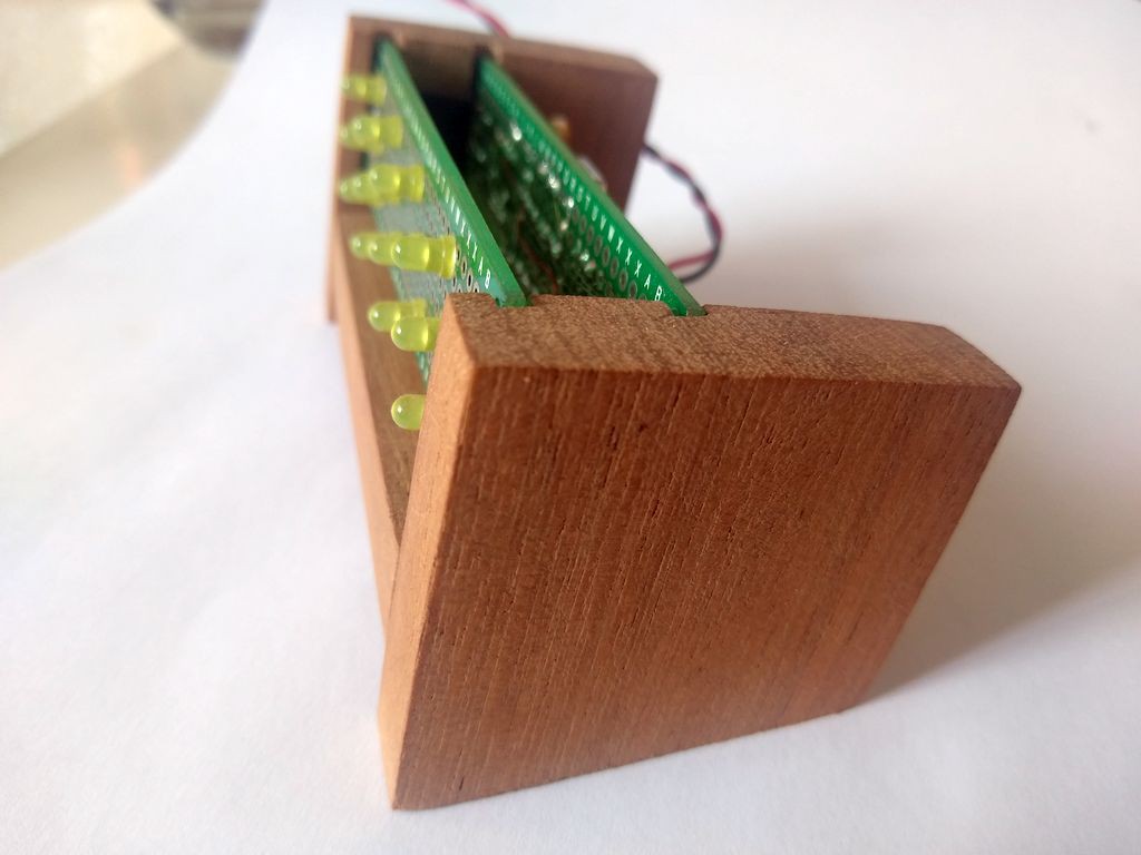
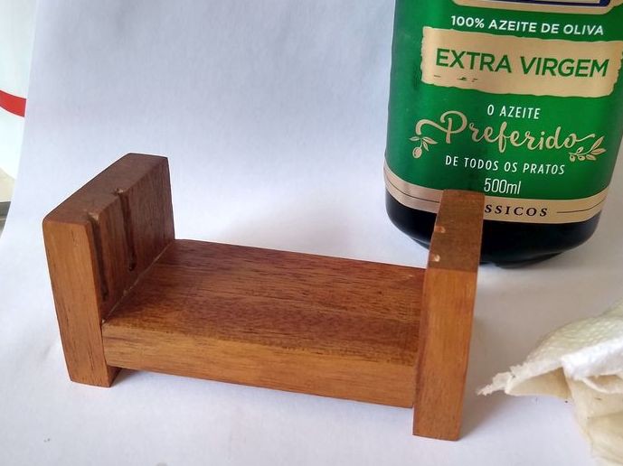
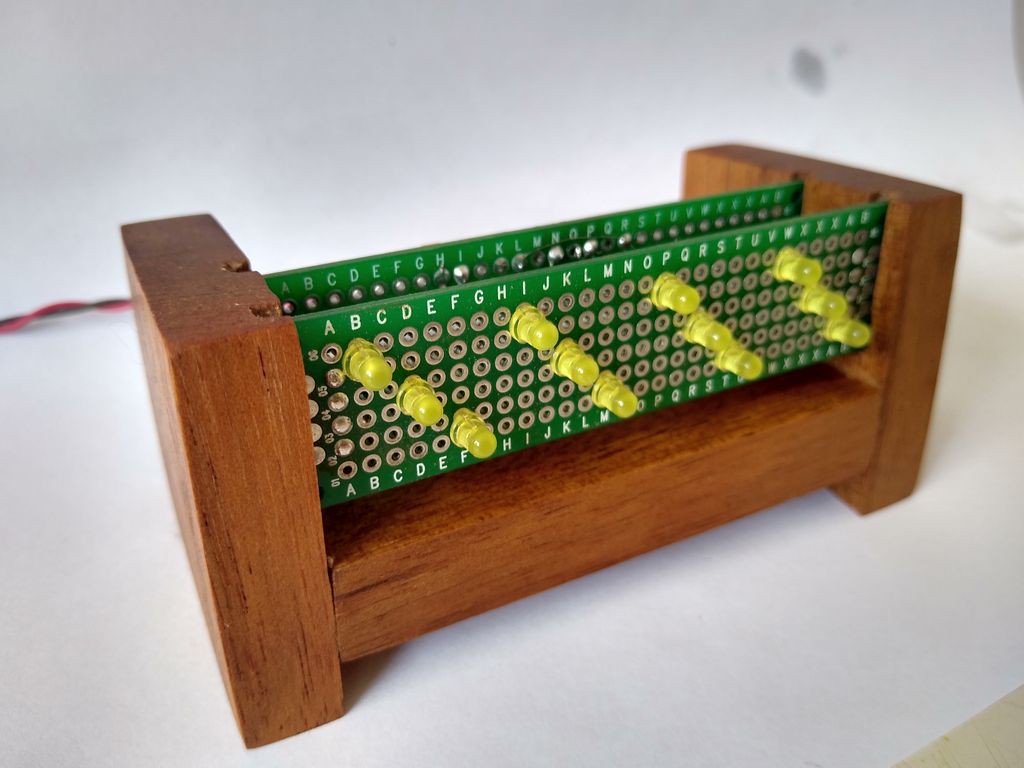
The unit is assemble on a handcrafted wooden base...
..and was finished using olive oil.
A micro-usb adapter provides power ( through a wall wart )
Testing
Here is a brief demonstration of the auto brightness adjustment;
And here is a demonstration of the time adjustment.
Usage
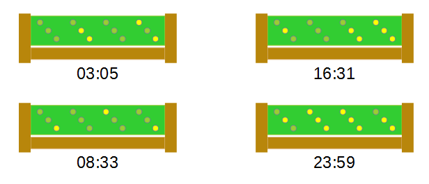
Do not try to do the math using 6 bits. The trick to read this clock is to read every 3-bit digit in binary and multiply the MSBs by 8 before summing to the LSBs.
 danjovic
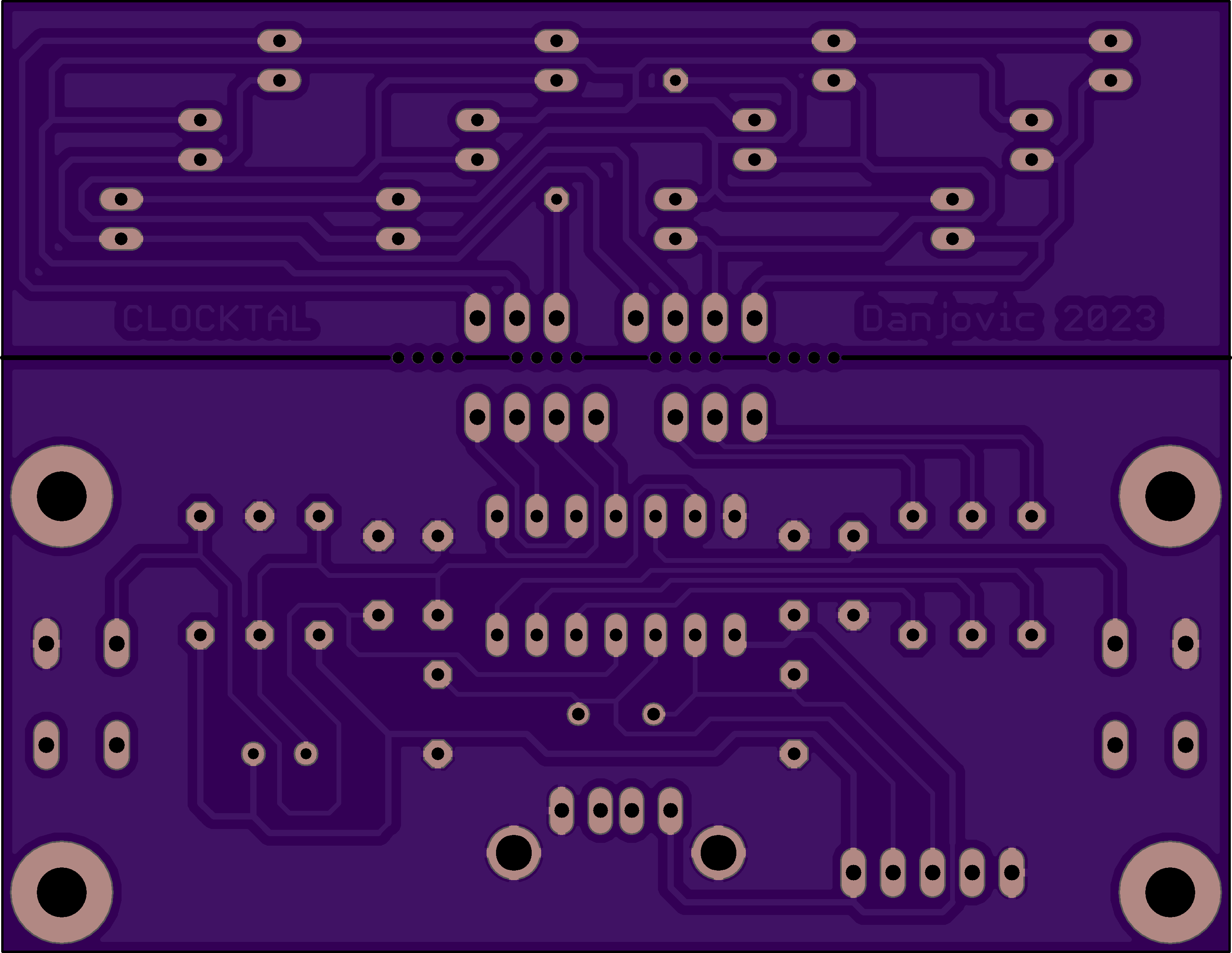

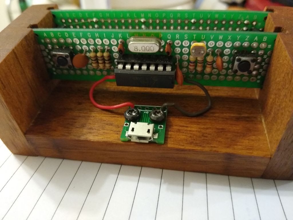
 Rear view, after trimming and soldering the wires.




 K.C. Lee
 Gigawatts
Thanks Ken! I liked the suggestion. I liked the suggestion. I should begin write one page with the pictures of all my clocks.